patent · US5452688
Method and apparatus for enhancing combustion in internal combustion engines
26 September 1995
Page 1 — bibliographic record
United States Patent (19) 11 Patent Number: 5,452,688 Rose 45) Date of Patent: Sep. 26, 1995 54 METHOD AND APPARATUS FOR 4,488,090 12/1984 Hancock ................................. 315/2O1 ENHANCENG COMBUSTION IN INTERNAL 4,763,610 8/1988 Thomas ....................................... 23/3 COMBUSTION ENGINES 5,105,773 4/1992 Cunningham et al ... 123/3 5,119,768 6/1992 Russell ........................................ 123/3 76 Inventor: Hugh W. Rose, 4126 E. Minnezona, 5,140,513 8/1992 Yokoyama .. ... 363/26 5,231,954 8/1993 Stowe .......................................... 123/3
Phoenix, Ariz. 85018 5,305,715 4/1994 Nissley ............................ 123/DIG. 12 (21) Appl. No.: 364,668 Primary Examiner-Henry C. Yuen Assistant Examiner-Erick Solis 22 Filed: Dec. 27, 1994 Attorney, Agent, or Firm-Warren F. B. Lindsley 51 int. Cl. ............... FO2B 43/08 57 ABSTRACT 52) U.S. Cl. ......................................... 123/3; 123/DEG, 12 58) Field of Search ....................... 123/3, 1 A, DIG. 12; A method and apparatus is disclosed for enhancing the 204/129, 278; 323/355; 363/26 combustion efficiency of an internal combustion engine having one or more combustion chambers. The apparatus (56) References Cited comprises an electrical power source having a voltage output, a power supply in electrical communication with
3,311,097 3/1967 Mittelstaedt ............................ 23/119 having a cathode and an anode immersed in an aqueous 3,648,668 3/1972 Pacheco ...... ... 123/3 electrolytic solution. The anode and the cathode are in 3,939,806 2/1976 Bradley ... ... 123/3 electrical communication with the power supply output. The 3,980,053 9/1976 Horvath ...................................... 12313 power supply optimizes the voltage output of the power 4,003,345 1/1977 Bradley .... ... 123/DIG. 12 source for use with the electrolytic cell. In turn, the elec 4,023,545 5/1977 Mosher et al. a - -- - - - 123/3 trolytic cell breaks down the aqueous solution into a mixture 4,107,008 8/1978 Horvath .................................. 204/129 of hydrogen and oxygen gases which is conveyed to the 4,11,160 9/1978 Talenti ..... ... 123IDIG. 12 combustion chamber of the engine.
4,246,080 1/1981 Shinn ....... ... 123/DIG. 2 4,271,793 6/1981 Valdespino .............................. 12311 A 4,339,324 7/1982 Haas ........................................ 204/270 13 Claims, 2 Drawing Sheets
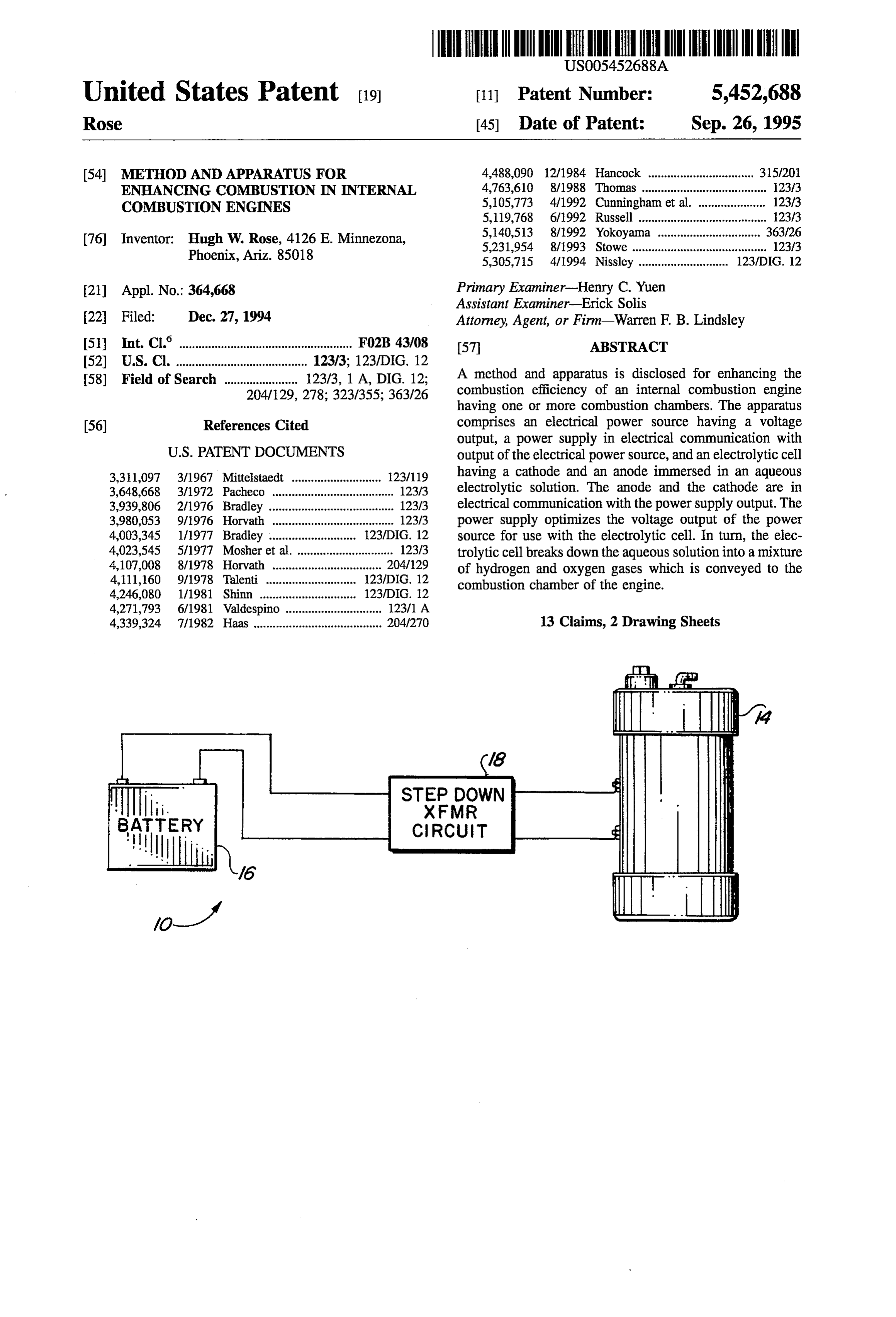
STEP DOWN
XFMR
CIRCUIT
Page 2
Drawing sheet — no readable text.
Page 3
Drawing sheet — no readable text.
Page 4
METHOD AND APPARATUS FOR It is still another object of this invention to provide an ENHANCNG COMBUSTION IN INTERNAL improved low voltage, low weight electrolytic cell for use in COMBUSTION ENGINES combination with internal combustion engines.
BACKGROUND OF THE INVENTION
Further objects and advantages of the invention will become apparent as the following description proceeds and
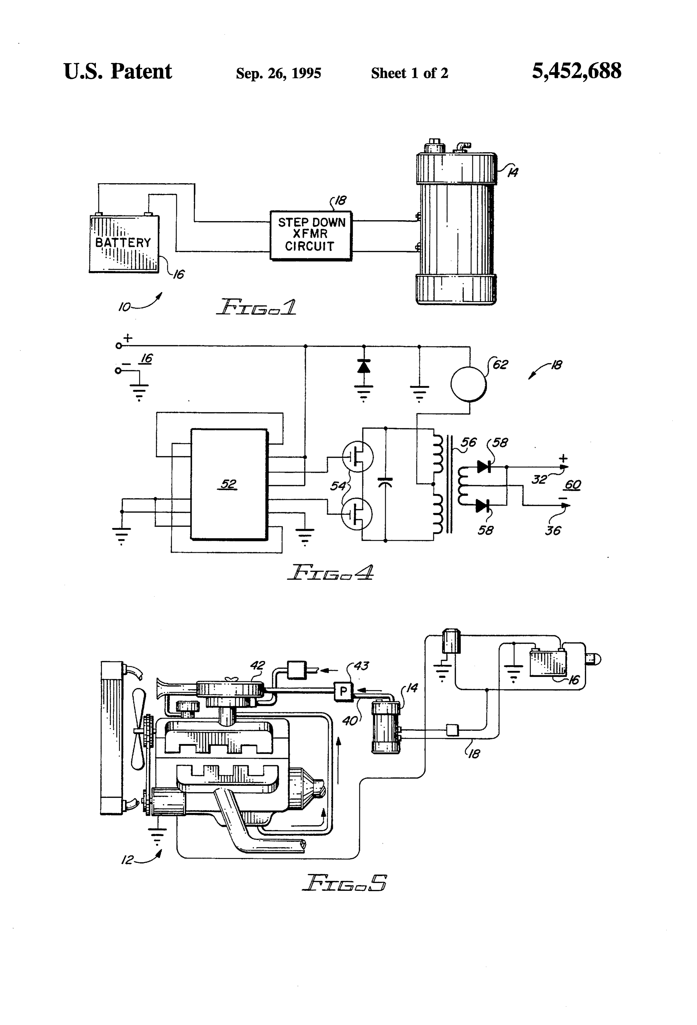
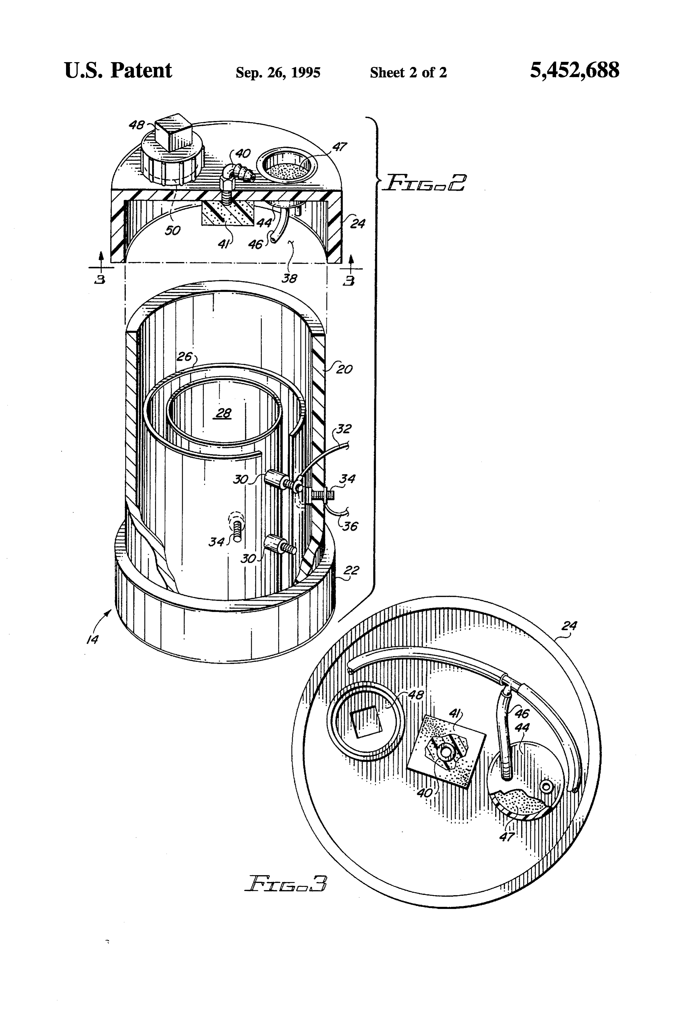
This invention relates to the use of electrolytic cells which the features of novelty which characterize this invention will generate a gaseous mixture of hydrogen and oxygen to be pointed out with particularity in the claims annexed to enhance the efficient burning of hydrocarbon fuels in inter and forming a part of this specification. nal combustion engines, and more particularly, to the use of 10 a power supply to provide optimum voltages to an electro BRIEF DESCRIPTION OF THE DRAWINGS lytic cell in an internal combustion engine. The present invention may be more readily described by Internal combustion engines are known to generate pol reference to the accompanying drawings in which: lutants because of the incomplete burning of hydrocarbon fuels for power. A number of attempts have been made to 5 FIG. 1 is a schematic view of the present invention; increase the efficiency of the combustion of hydrocarbon FIG. 2 is an exploded perspective side view of the fuel through the use of additives, in particular, hydrogen and electrolyte cell of FIG. 1;
oxygen generated from electrolytic cells and subsequently FIG. 3 is a cross sectional view of FIG. 2 taken along the introduced into the engine combustion chambers. line 3-3;
The systems proposed in the past have not achieved 20 FIG. 4 is a circuit diagram of the power supply in FIG. 1; public acceptance because of excessive weight, the danger and of excessive heat generated by the units, the need for rigid FIG. S is a schematic view of an alternate embodiment of control of the concentrations of electrolyte in the electrolytic the invention.
solution and freezing of the solutions which is encountered when low concentrations of electrolytic solutions are used. 25 DESCRIPTION OF THE PREFERRED In addition, the electrical power available with such engines, EMBODEMENT typically 12 to 14 volt batteries or alternators, does not provide the optimum voltage for use with an electrolytic Referring more particularly to the drawings by characters cell. of reference, FIGS. 1-4 disclose a system 10 for providing 30 hydrogen and oxygen to an internal combustion engine 12
DESCRIPTION OF THE PRIOR ART comprising an electrolytic cell 14, a power source 16 and a Heretofore a number of patents have been directed to the step down power supply circuit 18. In an automobile, power use of electrolytically generated hydrogen and oxygen to source 16 is a battery or an alternator having about a 12 enhance the combustion efficiency of internal combustion 35 volt/5 ampere DC output.
engines. As shown in FIG. 1, the voltage output from power source U.S. Pat. No. 3,311,097 entitled "Hydrogen-Oxygen 16 is directed through power supply circuit 18. Power supply Device in Combustion Engines' discloses the use of an circuit 18 is designed to optimize the voltage output of electrolytic cell to generate hydrogen and oxygen for sub source 16 for use with cell 14. In conjunction with an sequent enhancement of the combustion efficiency of an 40 internal combustion engine, power supply circuit 18 internal combustion engine. (XFMR) steps down the voltage output from about 12 U.S. Pat. No. 4,339,324 entitled “Polycell Gas Generator volts/5 amperes to about 3 volts/20 amperes. The stepped discloses a multiplicity of electrolytic cells arranged in a down voltage is directed to electrolytic cell 14 which is best stacked plate configuration that affords a high degree of seen in FIG. 2. For safety reasons, the stepped down voltage portability. should only reach the cell 14 when the vehicle is running.
U.S. Pat. No. 4,488,090 entitled "Advertising Sign Sys Electrolytic cell 14 includes a cylindrical housing 20, a tem' describes a low voltage system for supplying power to bottom cap 22 and a top cap 24. While the illustrated high voltage neon lights. embodiment shows the cell 14 as cylindrical in shape, of course many other shapes are possible. In the preferred
U.S. Pat. No. 5,105,773 entitled “Method and Apparatus embodiment, bottom cap 22 is permanently secured to for Enhancing Combustion in an Internal Combustion 50 housing 20 while top cap 24 is friction fitted. Thus, top cap Engine through Electrolysis' discloses a electrolytic cell 24 provides safety in that it will disengage in the event of a comprising a plurality of anodes and cathodes for careful pressure buildup in the interior of housing 20. control of the electrolytic output. A cylindrical cathode 26 is secured to the interior surface U.S. Pat. No. 5,231,954 entitled “Hydrogen/Oxygen Fuel of housing 20. Cathode 26 is secured to housing 20 by bolts Cell' discloses a fuel cell having a friction fitted top cap to 55 mitigate the danger of an explosion. 34 which are electrically connected at one end to cathode 26 and at the other end to negative input 36.
The known prior artis described above. None of this prior A cylindrical anode 28 is concentrically mounted within art disclose the device set forth herein. cathode 26. Anode 28 is secured to housing 20 by bolts 30 SUMMARY OF THE INVENTION 60 which are electrically insulated from cathode 26 but are electrically connected at one end to anode 28 and at the other
It is an object of this invention to provide an improved end to positive input 32.
electrolytic cell system which overcomes the disadvantages The use of a single cathode?anode combination in the of the previously known systems. present invention saves weight over previous systems. Since It is a further object of this invention to provide an 65 the voltage drop due to a single anode/cathode pair is about optimum voltage to an electrolytic cell for use with internal 2 volts, previous systems would employ as many as six such combustion engines. pairs for maximum efficiency. The present system achieves
Page 5
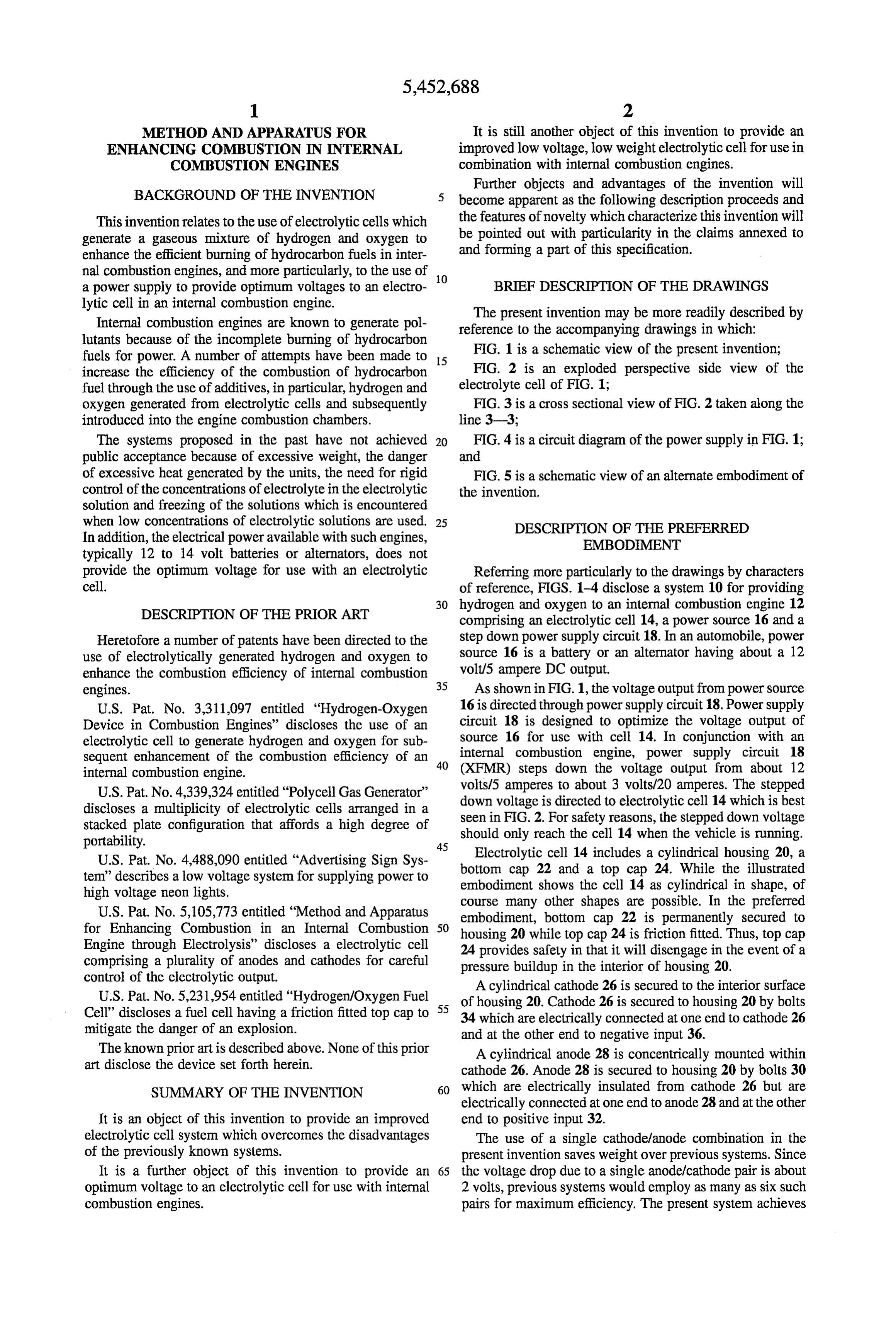
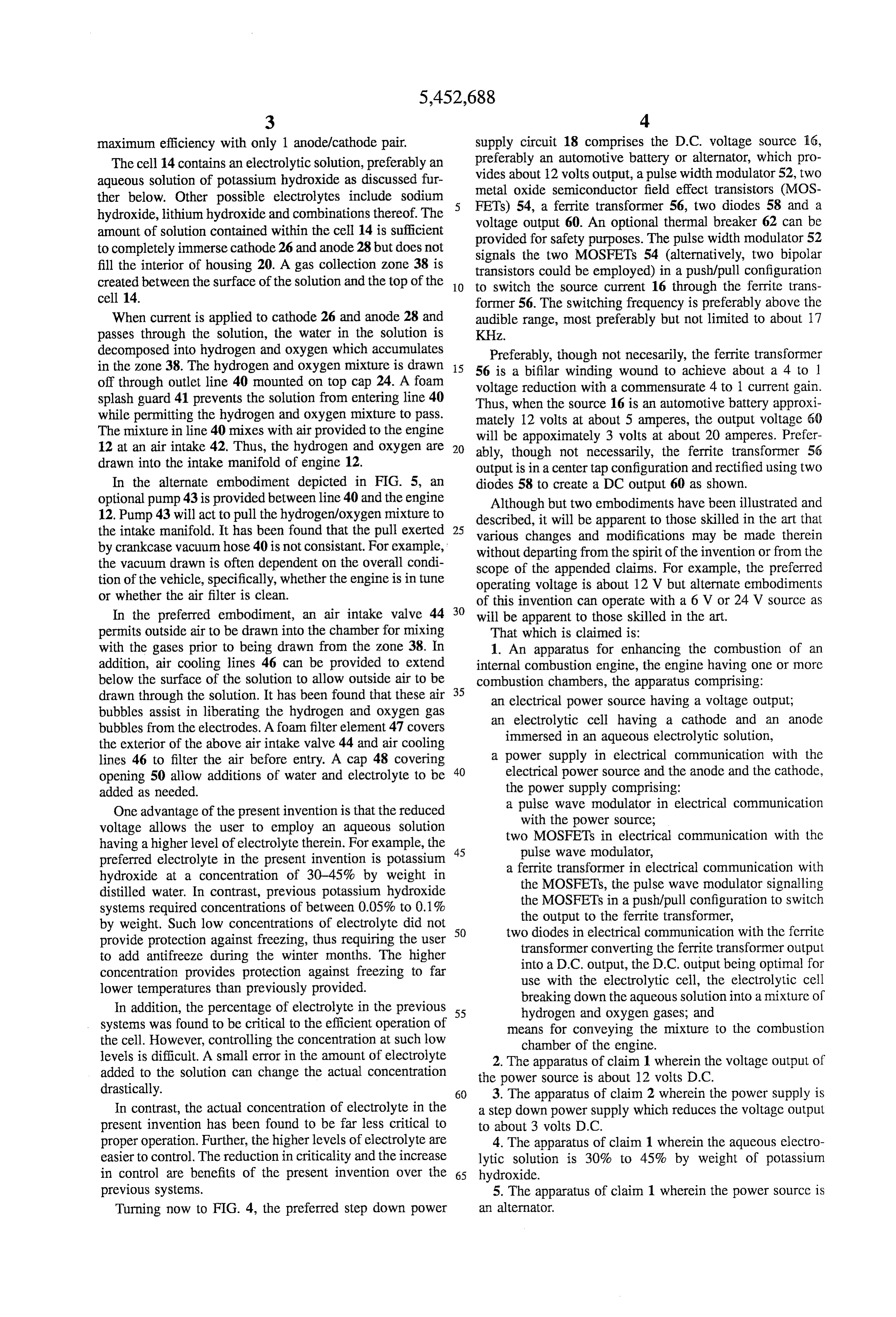
maximum efficiency with only 1 anode/cathode pair. supply circuit 18 comprises the D.C. voltage source i6, The cell 14 contains an electrolytic solution, preferably an preferably an automotive battery or alternator, which pro aqueous solution of potassium hydroxide as discussed fur vides about 12 volts output, a pulse width modulator 52, two ther below. Other possible electrolytes include sodium metal oxide semiconductor field effect transistors (MOS hydroxide, lithium hydroxide and combinations thereof. The FETs) 54, a ferrite transformer 56, two diodes 58 and a amount of solution contained within the cell 14 is sufficient voltage output 60. An optional thermal breaker 62 can be to completely immerse cathode 26 and anode 28 but does not provided for safety purposes. The pulse width modulator 52 signals the two MOSFETs 54 (alternatively, two bipolar fill the interior of housing 20. A gas collection zone 38 is transistors could be employed) in a push/pull configuration created between the surface of the solution and the top of the 10 to switch the source current 16 through the ferrite trans cell 14. former 56. The switching frequency is preferably above the When current is applied to cathode 26 and anode 28 and audible range, most preferably but not limited to about 17 passes through the solution, the water in the solution is KHZ.
decomposed into hydrogen and oxygen which accumulates Preferably, though not necesarily, the ferrite transformer in the Zone38. The hydrogen and oxygen mixture is drawn 5 56 is a bifilar winding wound to achieve about a 4 to 1 off through outlet line 40 mounted on top cap 24. A foam voltage reduction with a commensurate 4 to 1 current gain. splash guard 41 prevents the solution from entering line 40 Thus, when the source 16 is an automotive battery approxi while permitting the hydrogen and oxygen mixture to pass. mately 12 volts at about 5 amperes, the output voltage 60 The mixture in line 40 mixes with air provided to the engine will be appoximately 3 volts at about 20 amperes. Prefer 12 at an air intake 42. Thus, the hydrogen and oxygen are 20 ably, though not necessarily, the ferrite transformer 56 drawn into the intake manifold of engine 12. output is in a center tap configuration and rectified using two In the alternate embodiment depicted in FIG. 5, an diodes 58 to create a DC output 60 as shown. optional pump 43 is provided between line 40 and the engine Although but two embodiments have been illustrated and 12. Pump 43 will act to pull the hydrogen/oxygen mixture to described, it will be apparent to those skilled in the art that the intake manifold. It has been found that the pull exerted 25 various changes and modifications may be made therein by crankcase vacuum hose 40 is not consistant. For example, without departing from the spirit of the invention or from the the vacuum drawn is often dependent on the overall condi scope of the appended claims. For example, the preferred tion of the vehicle, specifically, whether the engine is in tune operating voltage is about 12 V but alternate embodiments or whether the air filter is clean. of this invention can operate with a 6 V or 24 V source as In the preferred embodiment, an air intake valve 44 30 will be apparent to those skilled in the art.
permits outside air to be drawn into the chamber for mixing That which is claimed is:
with the gases prior to being drawn from the zone 38. In 1. An apparatus for enhancing the combustion of an addition, air cooling lines 46 can be provided to extend internal combustion engine, the engine having one or more below the surface of the solution to allow outside air to be combustion chambers, the apparatus comprising: drawn through the solution. It has been found that these air 35 an electrical power source having a voltage output; bubbles assist in liberating the hydrogen and oxygen gas an electrolytic cell having a cathode and an anode bubbles from the electrodes. A foam filter element 47 covers the exterior of the above air intake valve 44 and air cooling immersed in an aqueous electrolytic solution, lines 46 to filter the air before entry. A cap 48 covering a power supply in electrical communication with the opening 50 allow additions of water and electrolyte to be 40 electrical power source and the anode and the cathode, added as needed. the power supply comprising: One advantage of the present invention is that the reduced a pulse wave modulator in electrical communication voltage allows the user to employ an aqueous solution with the power source;
two MOSFETs in electrical communication with the having a higher level of electrolyte therein. For example, the 45 pulse wave modulator, preferred electrolyte in the present invention is potassium a ferrite transformer in electrical communication with hydroxide at a concentration of 30-45% by weight in the MOSFETs, the pulse wave modulator signalling distilled water. In contrast, previous potassium hydroxide the MOSFETs in a push/pull configuration to switch systems required concentrations of between 0.05% to 0.1% the output to the ferrite transformer, by weight. Such low concentrations of electrolyte did not 50 two diodes in electrical communication with the ferrite provide protection against freezing, thus requiring the user transformer converting the ferrite transformer output to add antifreeze during the winter months. The higher into a D.C. output, the D.C. output being optimal for concentration provides protection against freezing to far use with the electrolytic cell, the electrolytic cell lower temperatures than previously provided. breaking down the aqueous solution into a mixture of In addition, the percentage of electrolyte in the previous 55 hydrogen and oxygen gases; and systems was found to be critical to the efficient operation of means for conveying the mixture to the combustion the cell. However, controlling the concentration at such low chamber of the engine.
levels is difficult. A small error in the amount of electrolyte 2. The apparatus of claim 1 wherein the voltage output of added to the solution can change the actual concentration the power source is about 12 volts D.C. drastically. 60 3. The apparatus of claim 2 wherein the power supply is In contrast, the actual concentration of electrolyte in the a step down power supply which reduces the voltage output present invention has been found to be far less critical to to about 3 volts D.C.
proper operation. Further, the higher levels of electrolyte are 4. The apparatus of claim 1 wherein the aqueous electro easier to control. The reduction in criticality and the increase lytic solution is 30% to 45% by weight of potassium in control are benefits of the present invention over the 65 hydroxide.
previous systems. 5. The apparatus of claim 1 wherein the power source is Turning now to FIG. 4, the preferred step down power an alternator.
Page 6
6. The apparatus of claim 1 wherein the power source is frequency is approximately 17 KHz. a battery. 11. The apparatus of claim 1 wherein the ferrite trans 7. The apparatus of claim 1 wherein the conveying means former is a bifilar winding wound to achieve about a 4 to 1 comprises an outlet line on the electrolytic cell connected to voltage drop with a commensurate 4 to 1 current gain. the combustion chambers of the engine. 12. The apparatus of claim 11 wherein the ferrite trans 8. The apparatus of claim 7 wherein the conveying means former is in a center tap output configuration. further comprises a pump connected to the outlet line 13. The apparatus of claim 12 wherein the output voltage directing the mixture to the combustion chamber. of the electrical power source is about 12 volts at 5 amperes 9. The apparatus of claim 1 wherein the MOSFETs switch and the D.C. output will be about 3 volts at 20 amperes. at a frequency above the audible range. 10 10. The apparatus of claim 9 wherein the switching ck k k g :
Provenance
- Collection
- Cited prior art
- Original PDF
- patentimages.storage.googleapis.com →
- Filed
- 1994-12-27
- Pages
- 6
- Method
- pdftotext (the PDF's own text layer) + pdftoppm 300dpi page scans
- Source
- Google Patents bibliographic record
- Granted
- 1995-09-26
- Inventors
- Hugh W. Rose
- Transcribed from
- patentimages.storage.googleapis.com →