patent · US20030159663A1
Hydrogen generation apparatus for internal combustion engines and method thereof
28 August 2003
Page 1 — bibliographic record
(19) United States (12) Patent Application Publication (10) Pub. No.: US 2003/0159663 A1
Zagaja et al. (43) Pub. Date: Aug. 28, 2003 (54) HYDROGEN GENERATION APPARATUS Publication Classification
FOR INTERNAL COMBUSTION ENGINES
AND METHOD THEREOF (51) Int. Cl." ...................................................... FO2B 43/08 (52) U.S. Cl. .................................................................. 123/3 (76) Inventors: John Zagaja, East Granby, CT (US);
Trent Molter, Glastonbury, CT (US); (57) ABSTRACT
Lawrence C. Moulthrop, Windsor, CT
(US); William Smith, Suffield, CT (US) A System and method are provided for generating hydrogen for use with an internal combustion engine. The System
Correspondence Address: includes a venturi device coupled with an exhaust Stream PROTON ENERGY SYSTEM from the internal combustion engine. The Venturi device 10 TECHNOLOGY DRIVE creates a gas flow through a condenser to generate reactant WALLINGFORD, CT 06492 (US) water. After the reactant water is polished to remove con taminants, hydrogen and oxygen are disassociated using a (21) Appl. No.: 10/081,666 PEM based electrolyzer. The hydrogen gas is used by the internal combustion engine to assist in the combustion (22) Filed: Feb. 22, 2002 process and reduce pollutant emissions.
Page 2
Drawing sheet — no readable text.
Page 3
Drawing sheet — no readable text.
Page 4
US 2003/O159663 A1 Aug. 28, 2003
HYDROGEN GENERATION APPARATUS FOR cathode. A portion of the process water exits the cell at the INTERNAL COMBUSTION ENGINES AND cathode Side without passing through the membrane, while METHOD THEREOF oxygen gas Saturated with water vapor exits the cell at the anode Side.
FIELD OF THE INVENTION
0007. In vehicle applications, it is necessary provide a 0001. This disclosure relates generally to the generation water Source to generate the hydrogen. Prior art Solutions of hydrogen utilizing exhaust from and internal combustion incorporate a water reservoir that must be periodically engine, and especially relates to the use of electrolysis of replenished. The disadvantage of this Solution is that it adds water for the generation of the hydrogen. an additional maintenance procedure for the engine operator. 0008 What is needed in the art is a hydrogen generation
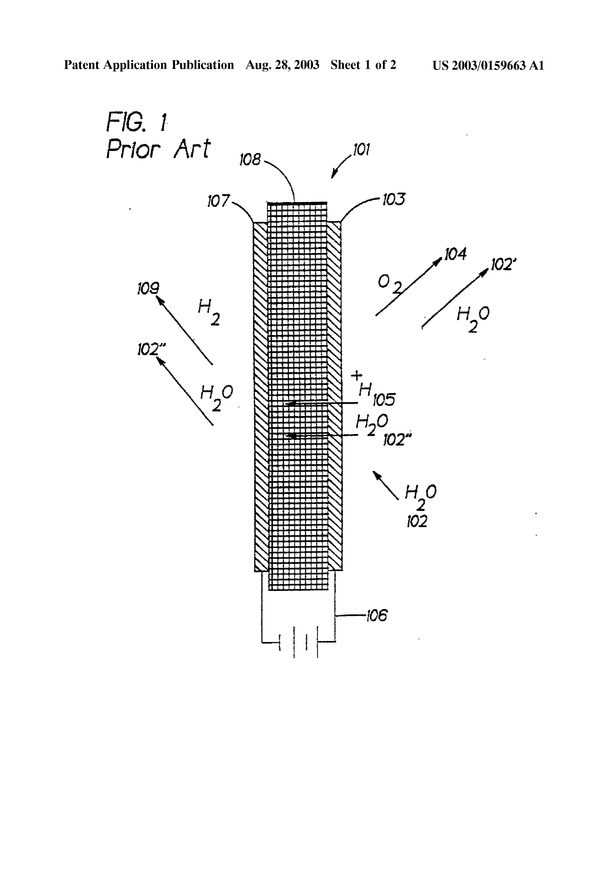
BRIEF DESCRIPTION OF THE RELATED ART System for use with an internal combustion engine that 0002. A typical internal combustion engine such as that requires minimal maintanence and a method for use thereof. generally used in automobiles, trucks and other vehicles use SUMMARY OF THE INVENTION hydrocarbon fuels for combustion. Since a portion of the hydrocarbon fuel remains unburned as the exhaust exits the 0009 Disclosed herein are hydrogen generation systems engine, pollutants are generated and released to the envi for use with internal combustion engines and methods for ronment. A number of attempts have been made to increase use thereof. An exemplary embodiment of the hydrogen the efficiency and completeneSS of combustion by utilizing generation System comprises: an exhaust venturi, a con catalysts and additives which decrease the quantity of pol denser in fluid communication with the Venturi, the con lutants post-combustion in the exhaust. denser extracting water from the exhaust Stream and an 0003. One additive used is the introduction of gaseous electrolyzer in fluid communication with the condenser, the hydrogen into the fuel mixture before combustion. When electrolyzer producing hydrogen gas. mixed and combusted with the hydrocarbon fuel, the gas 0010 Another embodiment of the hydrogen generation eous hydrogen enhances the flame Velocity and permits the System comprises: an exhaust venturi, an air inlet in fluid engine to operate with leaner fuel mixtures. Thus, hydrogen communication with the Venturi and ambient air, a con has a catalytic effect causing a more complete burn of the denser in fluid communication with the Venturi and the air existing fuel and yields a reduction in exhaust emissions. inlet, the condenser extracting water from the ambient air, 0004. Due to the advantages of hydrogen in reducing the and an electrolyzer in fluid communication with the con exhaust emissions, a number of attempts have been made to denser, the electrolyzer producing hydrogen gas. incorporate a System with vehicles. Unfortunately, gaseous 0011. One embodiment for an internal combustion engine hydrogen is not readily available to the general public. To comprises: an internal combustion engine, an exhaust pipe overcome this lack of availability, Systems using an elec coupled to the internal combustion engine, a condenser in trochemical cells have been proposed to provide the neces fluid communication with the exhaust pipe; and an electro Sary hydrogen. lyZer in fluid communication with the condenser; 0005 Electrochemical cells are energy conversion 0012 One embodiment for operating a hydrogen genera devices, usually classified as either electrolysis cells or fuel tion System for use with an internal combustion engine cells. A proton eXchange membrane electrolysis cell can comprises: drawing exhaust gas from an exhaust pipe, function as a hydrogen generator by electrolytically decom condensating water from Said exhaust gas, Storing Said posing Water to produce hydrogen and oxygen gas, and can water, and generating hydrogen from Said water. function as a fuel cell by electrochemically reacting hydro gen with oxygen to generate electricity. Referring to FIG. 1, 0013 Another embodiment for operating a hydrogen which is a partial Section of a typical anode feed electrolysis generation System comprises: creating gas flow with a cell 100, process water 102 is fed into cell 100 on the side Venturi, drawing ambient air into a condenser, condensing of an oxygen electrode (anode) 116 to form oxygen gas 104, water from the ambient air, Storing Said water, and gener electrons, and hydrogen ions (protons) 106. The reaction is ating hydrogen from Said water. facilitated by the positive terminal of a power source 120 0014. One embodiment for operating an internal com electrically connected to anode 116 and the negative termi bustion engine comprises: mixing hydrogen and hydrocar nal of power Source 120 connected to a hydrogen electrode bon fuel, combusting the fuel mixture, exhausting the com (cathode) 114. The oxygen gas 104, and a portion of the busted mixture, creating gas flow with an exhaust venturi, process water 108, exit cell 100, while protons 106 and drawing ambient air into a condenser, condensing water water 110 migrate acroSS a proton exchange membrane 118 from the ambient air, Storing Said water, and generating to cathode 114 where hydrogen gas 112 is formed. The hydrogen from Said water.
hydrogen gas 112 and the migrated water 110 exit cell 100 from the cathode side of the cell 100. 0015 The above discussed and other features will be appreciated and understood by those skilled in the art from 0006 Another typical water electrolysis cell using the the following detailed description and drawings. Same configuration as is shown in FIG. 1 is a cathode feed cell, wherein process water is fed on the Side of the hydrogen BRIEF DESCRIPTION OF THE DRAWINGS electrode. A portion of the water migrates from the cathode acroSS the membrane to the anode where hydrogen ions and 0016 Referring now to the drawings, which are meant to oxygen gas are formed due to the reaction facilitated by be exemplary and not limiting, and wherein like elements connection with a power Source acroSS the anode and are numbered alike:
Page 5
US 2003/O159663 A1 Aug. 28, 2003
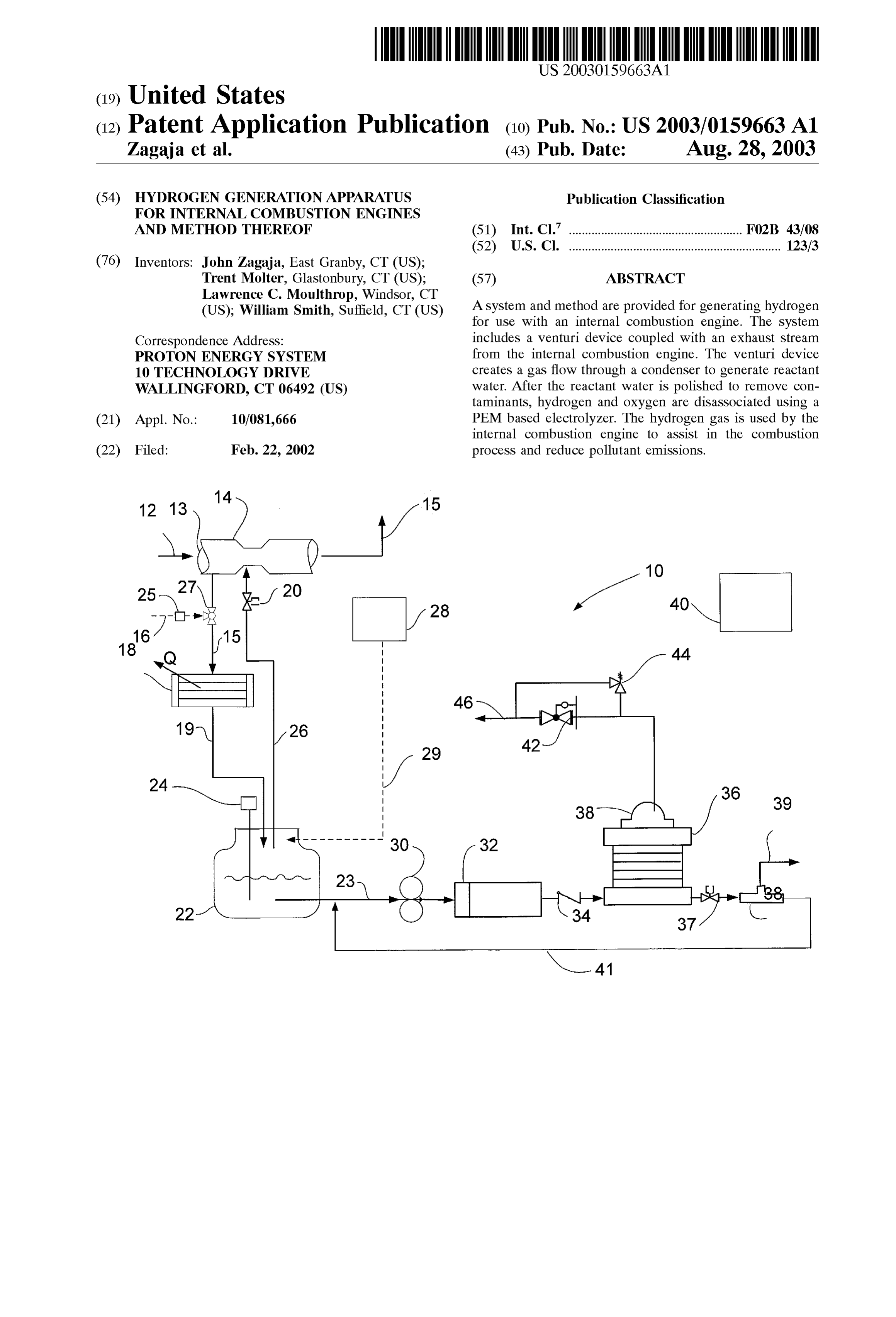
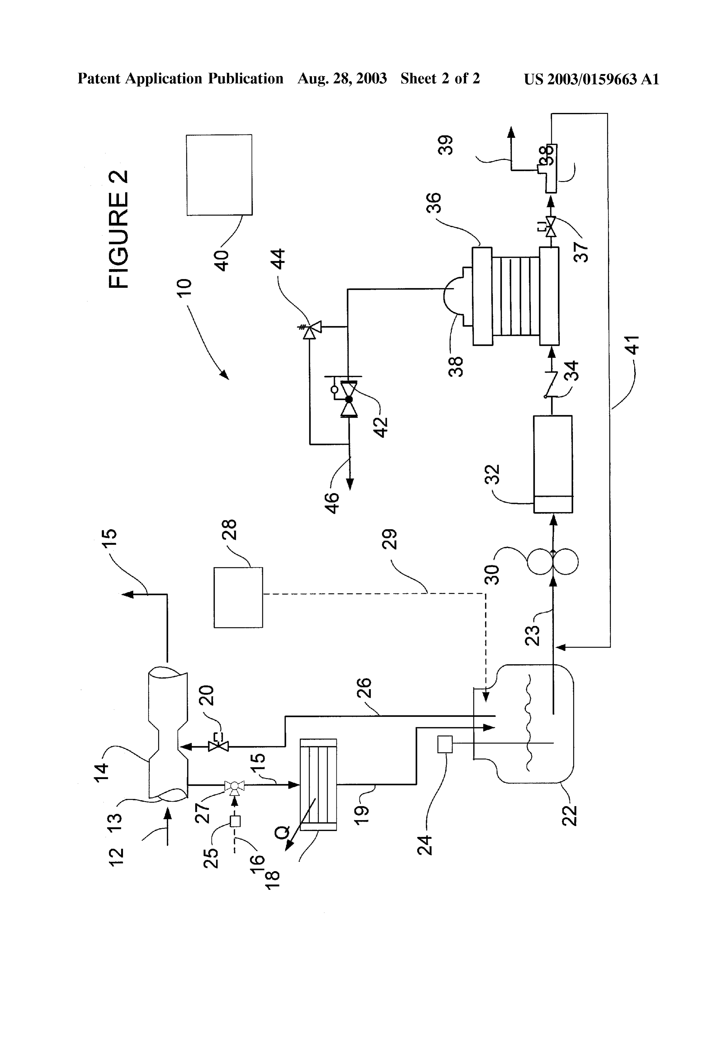
0017 FIG. 1 is a schematic diagram illustrating a prior return line 26 connects the reservoir 22 with the venturi 14 art electrochemical cell; and, via a valve 20. It is preferred that the valve 20 be a solenoid 0.018 FIG. 2 is a schematic diagram representing a valve that is actuated by a control System (not shown). A Sensor 24 is also connected to the reservoir 22 to detect and hydrogen generation System for use with an internal com provide feedback to the system on level of the water in the bustion engine. reservoir 22.
DETAILED DESCRIPTION OF THE 0022. If desired, an optional reserve line 28 and reserve PREFERRED EMBODIMENTS reservoir 28 may be included to provide a backup water Source during brief periods where humidity condensate may 0019. A wide variety of applications utilize internal com be unavailable. To minimize the maintenance requirements bustion engines to convert hydrocarbon fuels, Such as gaso of the reserve system, the reserve reservoir 28 may also line, diesel, natural gas and propane, into mechanical energy. perform as the Storage reservoir for other devices associated These include transportation applications, Such as automo with the application Such as a windshield wiper or the engine biles, trucks and the like, and Stationary applications Such as radiator. If the associated devices require additional com electrical generators. The one problem these applications pounds, e.g. methanol, ethylene-glycol, or propylene-glycol have in common is the pollution generated and released into to operate, additional reactant water polishing may be the atmosphere. Pollutants are caused by unburned or required to remove these compounds prior to use in the incomplete burning of the hydrocarbon fuel in the internal electrolysis process. The polishing may be accomplished by combustion engine. One technique employed to reduce either a additional device, or by the polisher 32. pollution emissions in the exhaust of the internal combustion 0023) A pump 30 is connected to the reactant water engine includes the addition of additives Such as hydrogen reservoir 22 by drain line 23. The pump moves the water into the hydrocarbon fuel prior to combustion. The hydrogen from the reservoir 22 to a water polisher 32. Any type of increases the flame Velocity of the fuel mixture during water polisher 32 known in the art may be used to remove combustion resulting in leSS non-combusted hydrocarbon contaminants from the the reactant water. Preferably, the fuel in the exhaust stream. polisher 32 will use a combination activated carbon/mixed 0020. A system 10 for generating hydrogen gas for use resin ion exchange bed to remove any contaminants. After with an internal combustion engine is shown in FIG. 2. An the reactant water is conditioned it moves through check exhaust stream 12 from an internal combustion engine (not valve 34 into the electrolyzer cell 36. shown) is routed away from engine through an exhaust pipe 0024. Electrolyzer cell stack 36 comprises a plurality of 13 in a typical manner well known in the art. A venturi 14 cells similar to cell 100 described above with reference to is along the exhaust pipe 13. While the venturi 14 can be FIG. 1 encapsulated within sealed structures (not shown). located anywhere along the length of the exhaust pipe 13, it The reactant water is received by manifolds or other types of is preferred that it is located downstream from a catalytic conduits (not shown) that are in fluid communication with device (e.g. a catalytic converter) which removes many of the cell components. An electrical Source compatible with a the pollutant compounds from the exhaust Stream 12. A tube power Source from the internal combustion engine is dis 15 connects a condenser 18 with the exhaust pipe 13. For posed in electrical communication with each cell within cell reasons that will be made clearer herein, it is preferred that stack 36 to provide a driving force for the dissociation of the the tube 15 be located upstream from the venturi 14. While Water.
engine exhaust alone could be used in the System, it is 0025 Oxygen and water exit cell stack 36 via a common preferable to provide an air inlet 16 connected to the tube 15 Stream through Valve 37 and are Separated in phase Separator to provide ambient air into the system 10. With the air inlet 38. Ultimately the water is returned to the drain line 23, 16 connected, the System has the option of using ambient air whereby the water is recycled and the oxygen is released to or exhaust gas to generate reactant water. A Sensor 25 Such the atmosphere via vent 39. Optionally, the oxygen may be as a, dew point Sensor, measures the properties of the returned back to the internal combustion engine to assist in ambient air. These properties may include ambient air tem enhancing combustion.
perature, relative humidity and/or dew point. The sensor 25 is connected to a control system 40 which determines which 0026. The hydrogen stream, which contains water, exits gas Stream would require a minimal condenser energy. A cell Stack 36 and is fed to a phase Separation/storage vessel valve 27 in response to the control system 40 will activate 38, which acts as a hydrogen/water Separation apparatus 44 to allow either exhaust gas or ambient air into the System 10. and a Storage vessel for holding the hydrogen until it is required by the internal combustion engine. Preferably, the 0021. The condenser 18 removes heat Q from either the vessel 38 is integral with the electrolyzer cell 36. However, engine exhaust 12 or the ambient air causing water to the phase Separation and Storage may be accomplished by condensate and collect in the reactant water reservoir 22 via Separate devices and be located remote from the electrolyzer line 19. The condenser 18 can be of any type capable of cell 36 depending on the needs of the application. If a cooling the gas to a temperature to its dew point. Preferably, non-pressurized device is desired, the hydrogen can be the condenser would be a conductive type cooler, Such as a Stored as a Solid, e.g., as a metal hydride, in a carbon based thermo-electro or liquid refrigerant cooler capable of remov Storage (e.g. particulates, nanofibers, nanotubes, or the like), ing at least 680 BTU/Hr of heat from the gas. Preferably the and others, as well as combinations comprising at least one condenser has the capacity to remove 300 to 700 BTU/hr of the foregoing Storage forms. The Storage capacity is Other types of condensers may include, but are not limited preferably at least 1 g of H2 gas, but may be anywhere from to, convection type coolerS Such as a fan Systems. Preferably, 0.25 g to about 10 g. This hydrogen Stream has a preSSure the liquid refrigerant System would be coupled a vehicle air that is preferably about 300 pounds per Square inch (psi), but conditioning System, or the internal combustion radiator. A which may be anywhere from about 1 psi to about 1000 psi.
Page 6
US 2003/O159663 A1 Aug. 28, 2003
Some water is removed from the hydrogen Stream at vessel separator. The valve 37 which is operated by the control 38 and may be returned to the electrolyzer via manifolds (not System 40 is opened and closed to maintain the appropriate shown). water level inside the cell. The oxygen gas is removed from the water and release to the atmosphere via vent 39. The 0027. The hydrogen gas exits the vessel 38 through excess water returns via line 41 to be recycled through the backpressure regulator 42 and enters the internal combustion pump 30 and polisher 32.
engine systems via line 46. A relief valve 44 is coupled to line 46 to vent H gas to the atmosphere in the event that 0032. As hydrogen gas is required by the internal com pressure in line 46 reached undesirable levels. bustion engine, the regulator releases hydrogen for use by the engine via line 46. Preferably the engine will consume 0028 All the valves, pumps and sensors are interfaced hydrogen at a rate of at least 1.1 mg/sec at 300 psi. with a control system 40. Control system 40 is a suitable 0033) While preferred embodiments have been shown electronic device capable of accepting data and instructions, and described, various modifications and Substitutions may executing the instructions to process the data, and presenting be made thereto without departing from the Spirit and Scope the results. Therefore, control system 40 can be a micropro of the invention. Accordingly, it is to be understood that the ceSSor, microcomputer, a minicomputer, an optical com present invention has been described by way of illustrations puter, a board computer, a complex instruction Set computer, and not limitation.
an ASIC (application specific integrated circuit), a reduced instruction Set computer, an analog computer, a digital What is claimed is:
computer, a molecular computer, a quantum computer, a 1. A System for generating hydrogen from an exhaust cellular computer, a Superconducting computer, a Supercom Stream from an internal combustion engine, the System puter, a Solid-State computer, a Single-board computer, a comprising:
buffered computer, a computer network, a desktop computer, a laptop computer, a Scientific computer, a Scientific calcu a venturi in fluid communication with an exhaust Stream; lator, or a hybrid of any of the foregoing. a condenser in fluid communication with Said Venturi, 0029. In addition to being coupled to one or more com Said condenser extracting water from Said exhaust ponents within system 10, control system 40 may also be Stream; and, coupled to external computer networkS Such as a Vehicle an electrolyzer in fluid communication with Said con control System or an engine emission control System. These denser, Said electrolyzer producing hydrogen gas. external Systems are configured to communicate with con 2. The System of claim 1 further comprising a fluid trol System 40 using a well-known computer communica reservoir for Storing Said water, Said reservoir in fluid tions protocol such as TCP/IP (Transmission Control Pro communication with Said condenser and Said electrolyzer. tocol/Internet Protocol), RS-232, Mod Bus, and the like. 3. The system of claim 2 wherein said fluid reservoir is in fluid communication with Said venturi, Said reservoir fluid 0.030. During operation, the exhaust from the internal communication with Said Venturi generating gas flow from combustion engine is routed through the pipe 13 and the Said reservoir to Said venturi.
venturi 14. Due to well known pressure effects of the 4. The System of claim 3 further comprising a polisher in Venturi, a low pressure Zone is created at the beginning of the fluid communication with Said reservoir and Said electro venturi. Since return line 26 is coupled to the venturi at this lyZer.
low preSSure Zone, the pressure differential will cause gas to 5. The System of claim 4 further comprising a gas Storage flow through line 15 either from the air inlet 16 or the vessel in fluid communication with Said electrolyzer oppo exhaust pipe upstream from the venturi. While the exhaust Site Said polisher.
gas may have a consistant humidity level, typically 3% 6. The System of claim 5 wherein Said gas Storage vessel relative humidity (R.H.), the ambient air may vary from as is integral with Said electrolyzer. low as 10% R.H. to as high as 100% R.H. Since ambient air 7. The System of claim 5 wherein Said gas Storage vessel may have a higher moisture content than the exhaust gases, holds hydrogen.
it is preferable to have the dew point sensor 25 detect the 8. The System of claim 7 wherein Said gas Storage vessel R.H. humidity of the ambient air and have the control system contains metal hydrides.
determine when it would require leSS condenser energy to 9. The System of claim 7 wherein Said gas Storage vessel condensate water vapor from the ambient air instead of the contains nanofibers or nanotubes. exhaust. Once the appropriate Source has been determined, 10. The system of claim 6 further comprising a phase the valve 27 is actuated to flow either exhaust gas or ambient Separator in fluid communication with Said electrolyzer, Said air into the condenser 18. Water which is removed from the air or exhaust is then stored in the reservoir 22 until it is phase Separator removing water from hydrogen gas.
needed by the electrolysis cell 36. As the hydrogen is 11. The system of claim 10 wherein said phase separator depleted from the vessel 38, additional reactant water is is integral with Said electrolyzer. drawn by the pump 30 through the polisher 32 and into the 12. The system of claim 10 further comprising a reserve reservoir in fluid communication with said fluid reservoir.
electrolysis cell 36. The check valve 34 is provided to 13. The system of claim 5 wherein said electrolyzer is in prevent back flow of the water from the electrolysis cell 36 into the polisher. fluid communication with the internal combustion engine. 14. The system of claim 1 wherein said electrolyzer 0031. In the electrolysis cell36, hydrogen and oxygen are utilizes a proton eXchange membrane to Separate the hydro disassociated. The hydrogen flows into the vessel 38 replen gen from the oxygen.
ishing the hydrogen used by the engine and the water oxygen 15. The system of claim 1 wherein said condenser is a combination exit the cell 36 through valve 37 to a phase thermo-electric cooler.
Page 7
US 2003/O159663 A1 Aug. 28, 2003
16. The system of claim 4 wherein said polisher includes 36. A System for generating hydrogen for use with an activated carbon and a mixed resin ion eXchange bed to internal combustion engine, the System comprising: remove contaminants from Said water.
17. A System for generating hydrogen for use with an a means for condensating water from a gas, internal combustion engine, the System comprising: a means for Storing Said condensated water, Said Storage an exhaust venturi; means coupled to Said condensating means, an air inlet in fluid communication with Said venturi and a means for electrolyzing Said Stored condensated water; and ambient air;
a condenser in fluid communication with Said venturi and a means for Storing Said hydrogen gas, Said air inlet, Said condenser extracting water from Said 37. The hydrogen generating system of claim 36 wherein ambient air; and, Said means for condensating is a thermo-electric cooler. 38. The hydrogen generating system of claim 37 wherein an electrolyzer in fluid communication with Said con Said gas is exhaust from an internal combustion engine. denser, Said electrolyzer producing hydrogen gas. 39. The hydrogen generating system of claim 38 wherein 18. The hydrogen generating system of claim 17 farther Said gas is air.
comprising a reservoir, Said reservoir being in fluid com 40. The hydrogen generating system of claim 36 wherein munication with Said condenser and Said venturi. Said electrolyzing means is a proton eXchange membrane 19. The hydrogen generating system of claim 18 farther electrolyzer.
comprising a polisher, Said polisher in fluid communication 41. The hydrogen generating System of claim 36 further with Said reservoir and Said electrolyzer. comprising a gas inlet means, Said gas inlet means including 20. The hydrogen generating system of claim 19 wherein an ambient air inlet and a exhaust gas inlet. Said polisher includes activated carbon and a mixed resinion 42. The hydrogen generating System of claim 41 further eXchange bed to remove contaminants from Said water. comprising a means for determining required condenser 21. The hydrogen generating System of claim 19 further energy, Said determining means coupled to Said inlet means. comprising a phase Separator, Said phase Separator in fluid 43. The hydrogen generating system of claim 36 further communication with Said electrolyzer. comprising a means for providing a reserve reservoir. 22. The hydrogen generating System of claim 21 wherein 44. The hydrogen generating System of claim 43 wherein Said phase Separator is integral with Said electrolyzer. Said reserve reservoir contains windshield wiper fluid. 23. The hydrogen generating System of claim 21 further 45. The hydrogen generating system of claim 36 wherein comprising a gas Storage vessel in fluid communication with Said gas Storage means is a metal hydride. Said phase Separator. 46. The hydrogen generating System of claim 36 wherein 24. The hydrogen generating System of claim 23 wherein Said gas Storage means is a nanofiber or a nanotube. Said gas Storage vessel is integral with Said phase Separator. 47. A System for generating hydrogen, Said System com 25. The hydrogen generating System of claim 23 wherein prising:
Said gas Storage vessel contains metal hydrides.
26. The hydrogen generating System of claim 23 wherein an internal combustion engine; Said gas Storage vessel contains nanofibers or nanotubes. an exhaust pipe coupled to Said internal combustion 27. The hydrogen generating System of claim 23 wherein engine;
Said condenser is a thermo-electric cooler.
28. The hydrogen generating System of claim 24 wherein an air inlet in fluid communication with Said exhaust pipe; Said electrolyzer includes a proton eXchange membrane. a condenser in fluid communication with Said exhaust 29. The hydrogen generating system of claim 23 further pipe and Said air inlet; and, comprising a reserve reservoir in fluid communication with
Said reservoir an electrolyzer in fluid communication with Said con 30. The hydrogen generating system of claim 23 further denser.
comprising a Sensor coupled to Said air inlet for determining 48. The hydrogen generating System of claim 47 wherein properties of Said ambient air. Said electrolyzer is in fluid communication with Said internal 31. The hydrogen generating System of claim 30 wherein combustion engine.
Said Sensor is a dew point Sensor. 49. The hydrogen generating system of claim 48 further 32. The hydrogen generating System of claim 31 wherein comprising a reservoir, Said reservoir in fluid communica Said Sensor measures ambient temperature and relative tion with Said condenser and Said electrolyzer. humidity. 50. The hydrogen generating system of claim 49 wherein 33. The hydrogen generating System of claim 30 including Said reservoir is in fluid communication with Said exhaust a valve in fluid communication with Said Venturi, Said air pipe.
inlet and Said condenser. 51. The hydrogen generating system of claim 49 further 34. The hydrogen generating system of claim 33 further comprising a polisher in fluid communication with Said comprising means for determining required condenser reservoir and Said electrolyzer. energy, said means operably connected to Said said Sensor 52. The hydrogen generating system of claim 47 further and Said valve. comprising a valve coupled to Said exhaust pipe, Said air 35. The hydrogen generating system of claim 34 further inlet and Said condenser.
comprising means for operating Said valve in response to 53. The hydrogen generating system of claim 52 further Said condenser energy means. comprising an air Sensor coupled to Said air inlet.
Page 8
US 2003/O159663 A1 Aug. 28, 2003
54. The hydrogen generating system of claim 53 further 67. The method of generating hydrogen of claim 66 comprising a means for determining condenser energy further comprising the Step of Separating oxygen from Said coupled to Said valve and Said Sensor. reactant Water.
55. The hydrogen generating system of claim 54 further 68. The method of generating hydrogen of claim 66 comprising a reserve reservoir in fluid communication with further comprising the Step of regulating the flow of hydro Said reservoir. gen to the internal combustion engine. 56. The hydrogen generating system of claim 55 wherein 69. A method for generating hydrogen for use with an Said reserve reservoir contains a fluid composed of water internal combustion engine comprising the Steps of and methanol.
57. The hydrogen generating system of claim 55 wherein generating pressure using an exhaust pipe from an internal Said reserve reservoir contains a fluid composed of water combustion engine;
and ethylene-glycol. detecting the dew point of ambient air; 58. The hydrogen generating system of claim 56 further comprising a gas Storage vessel in fluid communication with determining the appropriate gas which would minimize Said electrolyzer. condenser energy, 59. The hydrogen generating system of claim 58 wherein condensating reactant water from Said gas, and, Said gas Storage vessel contains metal hydrides.
60. The hydrogen generating system of claim 58 wherein generating hydrogen from Said reactant water. Said gas Storage vessel contains nanofibers or nanotubes. 70. The method of generating hydrogen of claim 69 61. A method for generating hydrogen for use with an wherein Said gas is exhaust gas.
internal combustion engine comprising the Steps of: 71. The method of generating hydrogen of claim 69 generating pressure using an exhaust pipe from an internal wherein Said gas is air.
combustion engine; 72. The method of generating hydrogen of claim 69 further comprising the Step of flowing Said gas through a condensating reactant water from a gas, and, condenser.
generating hydrogen from Said reactant water. 73. The method of generating hydrogen of claim 72 62. The method of generating hydrogen of claim 61 further comprising the Step of Storing Said reactant water. wherein Said gas is exhaust gas. 74. The method of generating hydrogen of claim 73 63. The method of generating hydrogen of claim 61 further comprising the Step of polishing Said reactant water wherein said gas is air. to remove contaminants.
64. The method of generating hydrogen of claim 61 75. The method of generating hydrogen of claim 74 further comprising the Step of flowing Said gas through a further comprising the Step of Separating oxygen from Said condenser. reactant Water.
65. The method of generating hydrogen of claim 62 76. The method of generating hydrogen of claim 74 further comprising the Step of Storing Said reactant water. further comprising the Step of regulating the flow of hydro 66. The method of generating hydrogen of claim 65 gen to the internal combustion engine. further comprising the Step of polishing Said reactant water to remove contaminants. k k k k k
Provenance
- Collection
- Patents citing this work
- Current assignee
- Proton Energy Systems Inc
- Pages
- 8
- Method
- pdftotext (the PDF's own text layer) + pdftoppm 300dpi page scans
- Patent office record
- patents.google.com →
- Source
- Google Patents citing-documents table
- Inventors
- John Zagaja; Trent Molter; Lawrence Moulthrop; William Smith
- Published
- 2003-08-28
- Transcribed from
- patentimages.storage.googleapis.com →