patent · US5143025
Hydrogen and oxygen system for producing fuel for engines
1 September 1992
Page 1 — bibliographic record
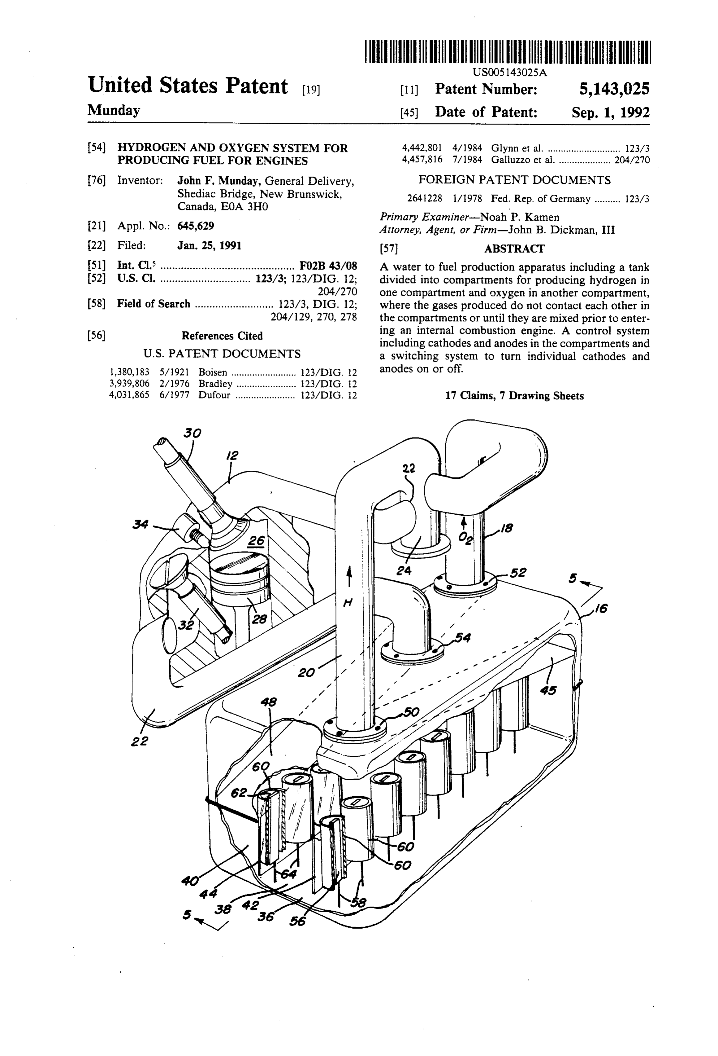
United States Patent 19) 11) Patent Number: 5,143,025 Munday 45) Date of Patent: Sep. 1, 1992 54) HYDROGEN AND OXYGEN SYSTEM FOR 4,442,801 4/1984 Glynn et al. ............................ 123/3 PRODUCING FUEL FOR ENGINES 4,457,816 7/1984 Galluzzo et al. .................... 204/270 76 Inventor: John F. Munday, General Delivery, FOREIGN PATENT DOCUMENTS Shediac Bridge, New Brunswick, 2641228 1/1978 Fed. Rep. of Germany .......... 23/3 Canada, E0A 3HO
Primary Examiner-Noah P. Kamen 21) Appl. No.: 645,629 Attorney, Agent, or Firm-John B. Dickman, III 22 Filed: Jan. 25, 1991 (57) ABSTRACT 51) Int. Cl. .............................................. F02B 43/08 A water to fuel production apparatus including a tank 52 U.S. Cl. ............................... 123/3; 123/DIG. 12; divided into compartments for producing hydrogen in 204/270 one compartment and oxygen in another compartment, 58) Field of Search ........................... 123/3, DIG. 12; where the gases produced do not contact each other in 204/129, 270, 278 the compartments or until they are mixed prior to enter o ing an internal combustion engine. A control system (56) References Cited including cathodes and anodes in the compartments and
l,380,183 5/1921 Boisen ......................... 123/DIG. 12 anodes on or off.
4,031,865 6/1977 Dufour ....................... 123ADIG 2 17 Claims, 7 Drawing Sheets
Page 2
Drawing sheet — no readable text.
Page 3
Drawing sheet — no readable text.
Page 4
Drawing sheet — no readable text.
Page 5
Drawing sheet — no readable text.
Page 6
Drawing sheet — no readable text.
Page 7
Drawing sheet — no readable text.
Page 8
Drawing sheet — no readable text.
Page 9
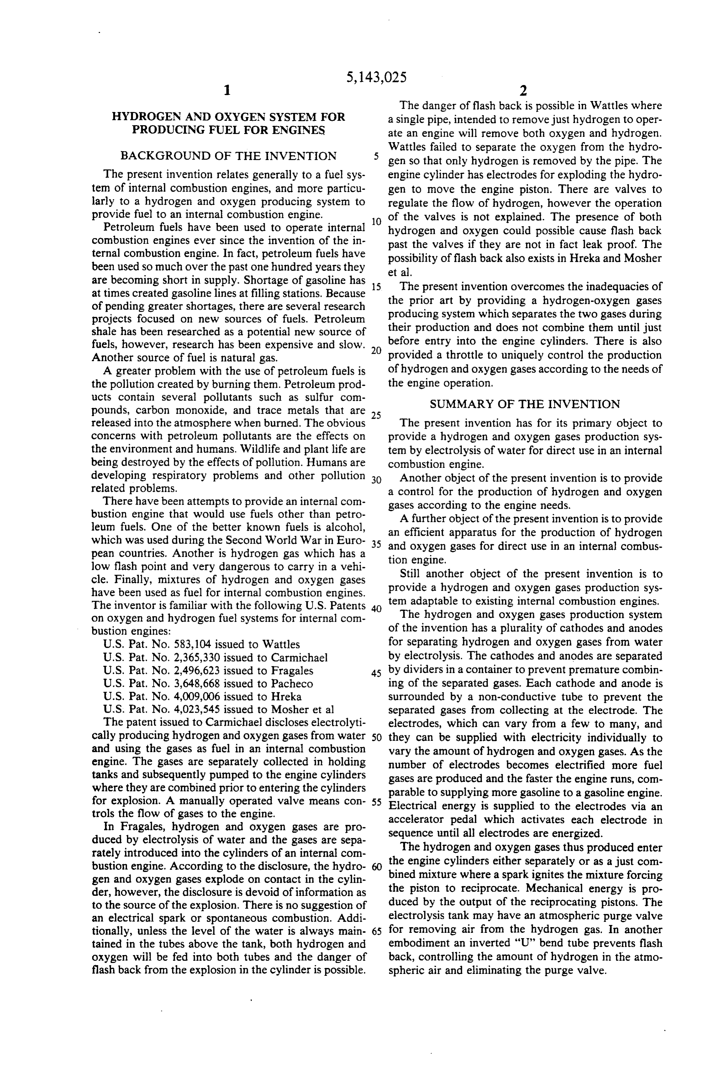
The danger of flash back is possible in Wattles where
HYDROGEN AND OXYGEN SYSTEM FOR a single pipe, intended to remove just hydrogen to oper PRODUCING FUEL FOR ENGINES ate an engine will remove both oxygen and hydrogen.
Wattles failed to separate the oxygen from the hydro gen so that only hydrogen is removed by the pipe. The
The present invention relates generally to a fuel sys engine cylinder has electrodes for exploding the hydro tem of internal combustion engines, and more particu gen to move the engine piston. There are valves to larly to a hydrogen and oxygen producing system to regulate the flow of hydrogen, however the operation provide fuel to an internal combustion engine. of the valves is not explained. The presence of both Petroleum fuels have been used to operate internal 10 hydrogen and oxygen could possible cause flash back combustion engines ever since the invention of the in past the valves if they are not in fact leak proof. The ternal combustion engine. In fact, petroleum fuels have possibility of flash back also exists in Hreka and Mosher been used so much over the past one hundred years they et al.
are becoming short in supply. Shortage of gasoline has 15 The present invention overcomes the inadequacies of at times created gasoline lines at filling stations. Because the prior art by providing a hydrogen-oxygen gases of pending greater shortages, there are several research projects focused on new sources of fuels. Petroleum producing system which separates the two gases during shale has been researched as a potential new source of their before production and does not combine them until just entry into the engine cylinders. There is also fuels, however, research has been expensive and slow. 20
Another source of fuel is natural gas. provided a throttle to uniquely control the production A greater problem with the use of petroleum fuels is of hydrogen and oxygen gases according to the needs of the pollution created by burning them. Petroleum prod the engine operation, ucts contain several pollutants such as sulfur com SUMMARY OF THE INVENTION pounds, carbon monoxide, and trace metals that are 25 released into the atmosphere when burned. The obvious The present invention has for its primary object to concerns with petroleum pollutants are the effects on provide a hydrogen and oxygen gases production sys the environment and humans. Wildlife and plant life are ten by electrolysis of water for direct use in an internal being destroyed by the effects of pollution. Humans are combustion engine.
developing respiratory problems and other pollution 30 Another object of the present invention is to provide related problems. a control for the production of hydrogen and oxygen There have been attempts to provide an internal com gases according to the engine needs. bustion engine that would use fuels other than petro A further object of the present invention is to provide leum fuels. One of the better known fuels is alcohol, an efficient apparatus for the production of hydrogen which was used during the Second World War in Euro 35 and oxygen gases for direct use in an internal combus pean countries. Another is hydrogen gas which has a tion engine.
low flash point and very dangerous to carry in a vehi Still another object of the present invention is to cle. Finally, mixtures of hydrogen and oxygen gases provide a hydrogen and oxygen gases production sys have been used as fuel for internal combustion engines. tem adaptable to existing internal combustion engines. The inventor is familiar with the following U.S. Patents The hydrogen and oxygen gases production system on oxygen and hydrogen fuel systems for internal con bustion engines: of the invention has a plurality of cathodes and anodes U.S. Pat. No. 583,104 issued to Wattles for separating hydrogen and oxygen gases from water U.S. Pat. No. 2,365,330 issued to Carmichael by electrolysis. The cathodes and anodes are separated U.S. Pat. No. 2,496,623 issued to Fragales 45 by dividers in a container to prevent premature combin U.S. Pat. No. 3,648,668 issued to Pacheco ing of the separated gases. Each cathode and anode is U.S. Pat. No. 4,009,006 issued to Hireka surrounded by a non-conductive tube to prevent the U.S. Pat. No. 4,023,545 issued to Mosher et al separated gases from collecting at the electrode. The The patent issued to Carmichael discloses electrolyti electrodes, which can vary from a few to many, and cally producing hydrogen and oxygen gases from water 50 they can be supplied with electricity individually to and using the gases as fuel in an internal combustion vary the amount of hydrogen and oxygen gases. As the engine. The gases are separately collected in holding number of electrodes becomes electrified more fuel tanks and subsequently pumped to the engine cylinders gases are produced and the faster the engine runs, com where they are combined prior to entering the cylinders for explosion. A manually operated valve means con 55 parable to supplying more gasoline to a gasoline engine. Electrical energy is supplied to the electrodes via an trols the flow of gases to the engine. accelerator pedal which activates each electrode in In Fragales, hydrogen and oxygen gases are pro sequence until all electrodes are energized. duced by electrolysis of water and the gases are sepa The hydrogen and oxygen gases thus produced enter rately introduced into the cylinders of an internal com the engine cylinders either separately or as a just com bustion engine. According to the disclosure, the hydro gen and oxygen gases explode on contact in the cylin bined mixture where a spark ignites the mixture forcing der, however, the disclosure is devoid of information as the piston to reciprocate. Mechanical energy is pro to the source of the explosion. There is no suggestion of duced by the output of the reciprocating pistons. The an electrical spark or spontaneous combustion. Addi electrolysis tank may have an atmospheric purge valve tionally, unless the level of the water is always main 65 for removing air from the hydrogen gas. In another tained in the tubes above the tank, both hydrogen and embodiment an inverted “U” bend tube prevents flash oxygen will be fed into both tubes and the danger of back, controlling the amount of hydrogen in the atmo flashback from the explosion in the cylinder is possible. spheric air and eliminating the purge valve.
Page 10
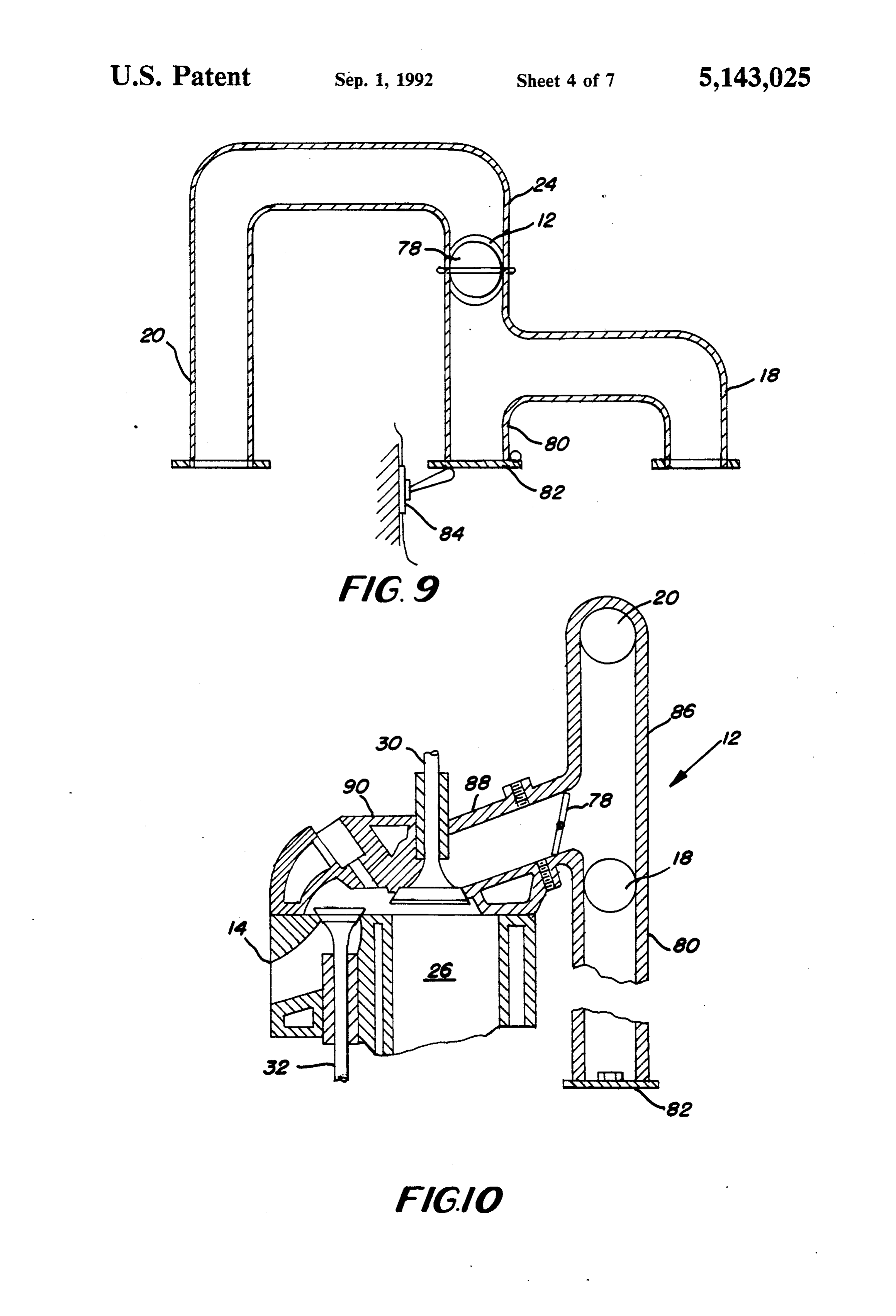
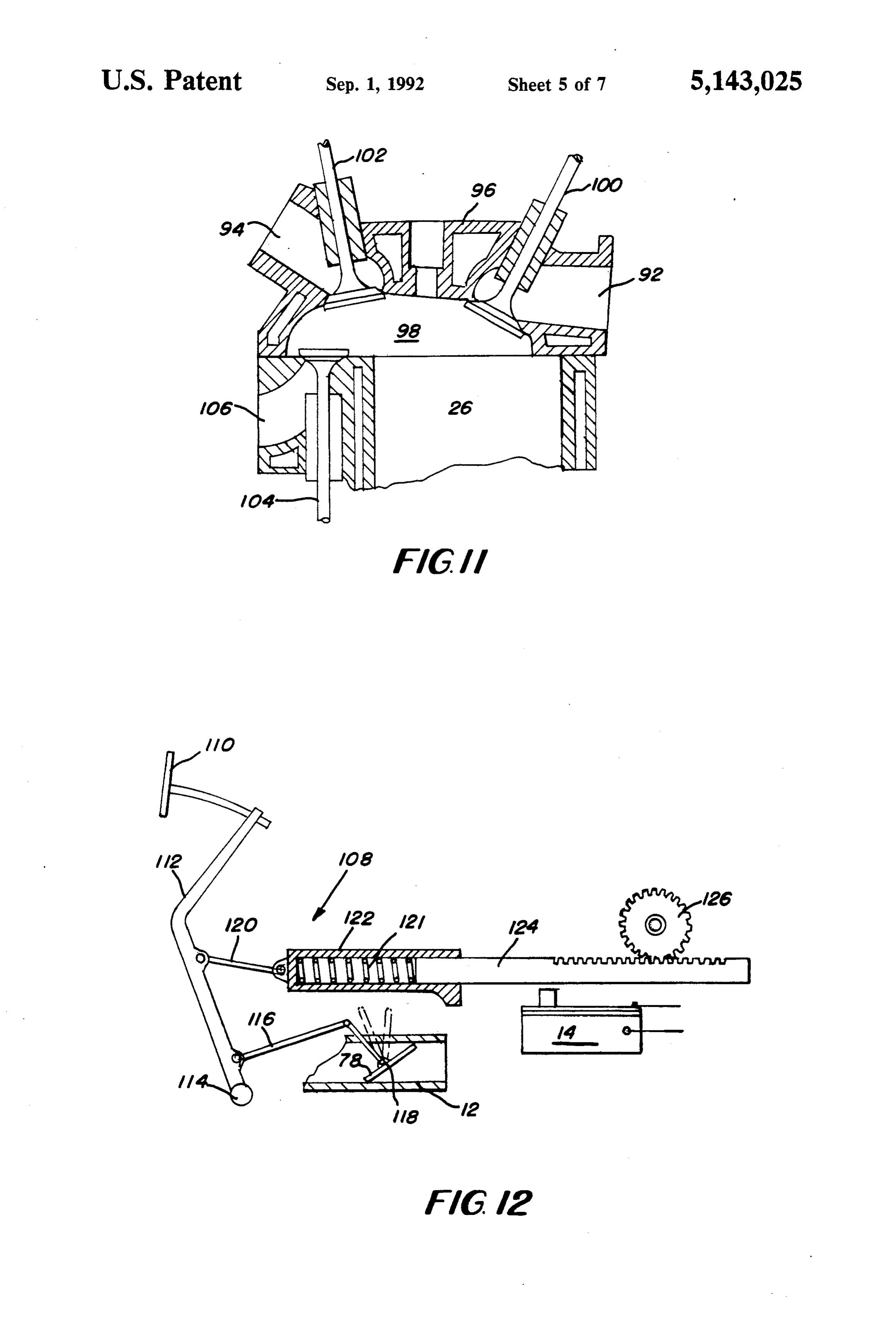
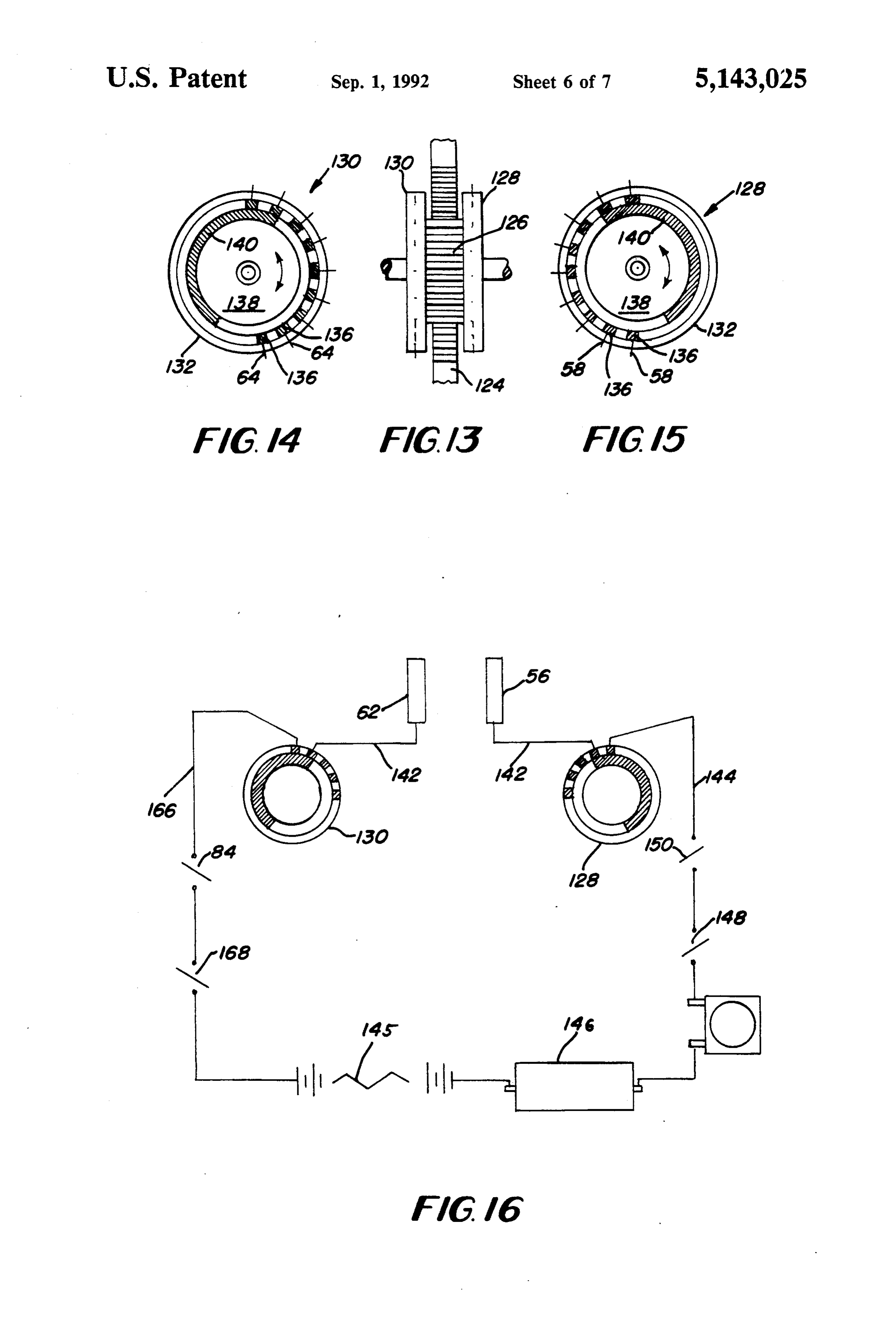
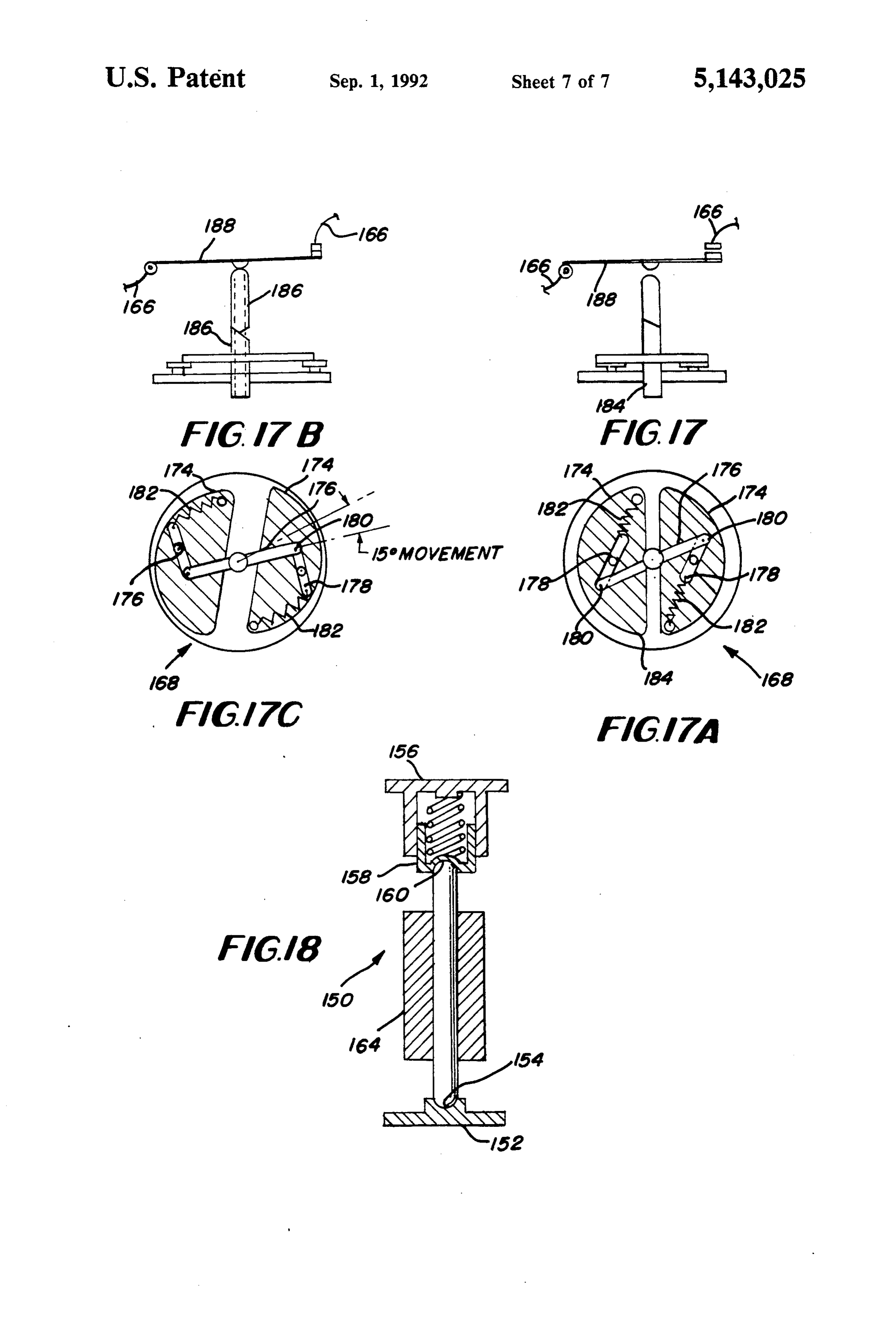
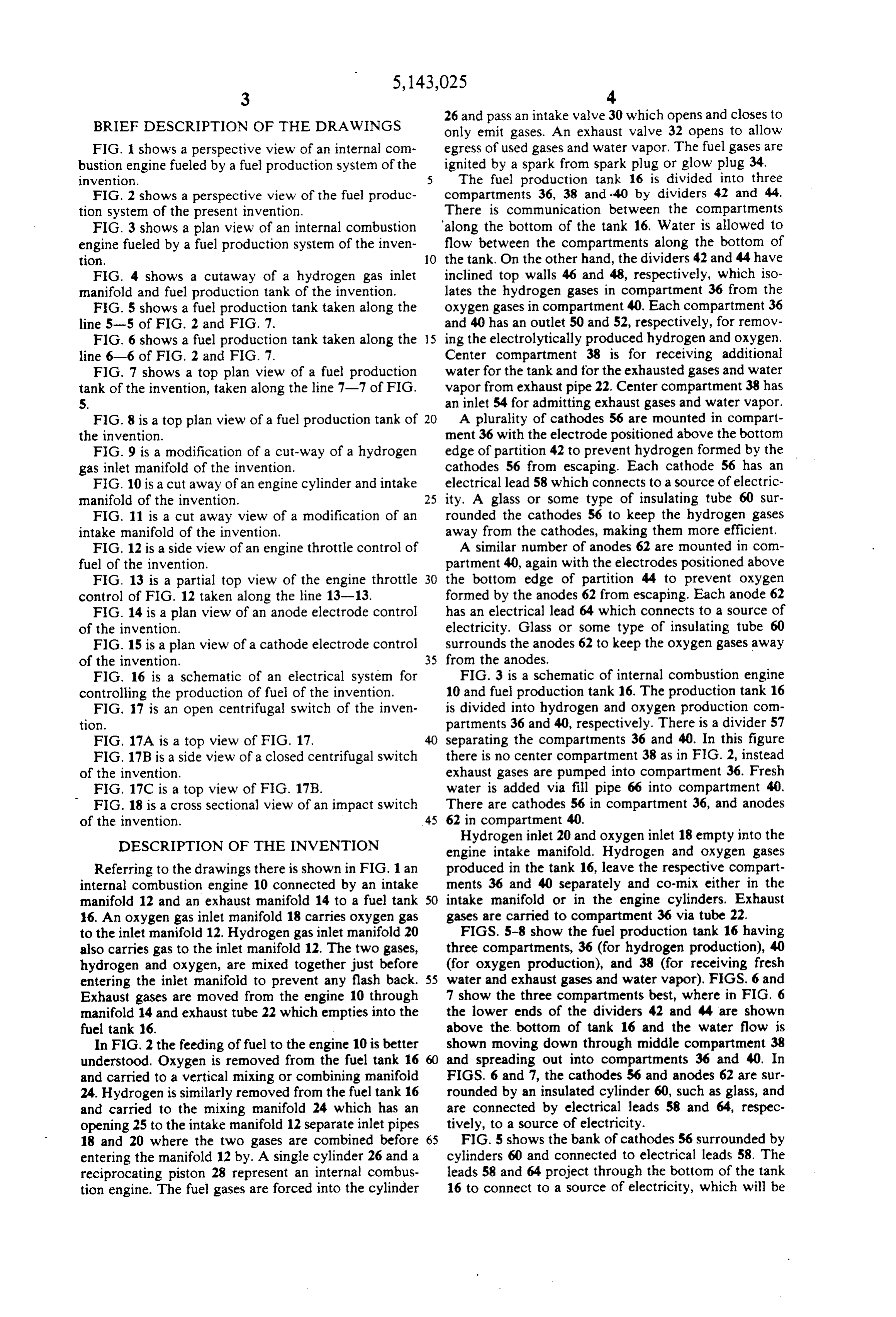
BRIEF DESCRIPTION OF THE DRAWINGS
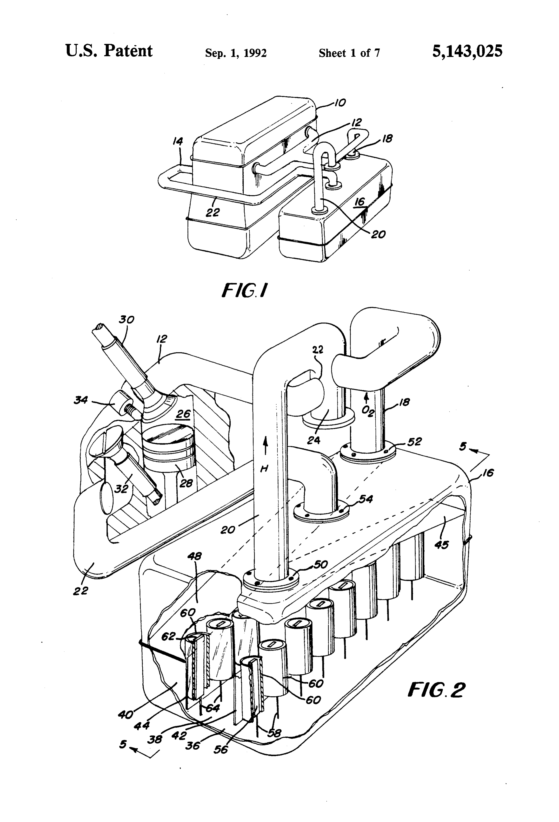
26 and pass an intake valve 30 which opens and closes to only emit gases. An exhaust valve 32 opens to allow
FIG. 1 shows a perspective view of an internal com egress of used gases and water vapor. The fuel gases are bustion engine fueled by a fuel production system of the ignited by a spark from spark plug or glow plug 34, invention. 5 The fuel production tank 16 is divided into three FIG. 2 shows a perspective view of the fuel produc compartments 36, 38 and 40 by dividers 42 and 44. tion system of the present invention. There is communication between the compartments FIG. 3 shows a plan view of an internal combustion along the bottom of the tank 16. Water is allowed to engine fueled by a fuel production system of the inven flow between the compartments along the bottom of tion. 10 the tank. On the other hand, the dividers 42 and 44 have FIG. 4 shows a cutaway of a hydrogen gas inlet inclined top walls 46 and 48, respectively, which iso manifold and fuel production tank of the invention. lates the hydrogen gases in compartment 36 from the FIG. 5 shows a fuel production tank taken along the oxygen gases in compartment 40. Each compartment 36 line 5-5 of FIG. 2 and FIG. 7. and 40 has an outlet 50 and 52, respectively, for remov FIG. 6 shows a fuel production tank taken along the 15 ing the electrolytically produced hydrogen and oxygen. line 6-6 of FIG. 2 and FIG. 7. Center compartment 38 is for receiving additional FIG. 7 shows a top plan view of a fuel production water for the tank and for the exhausted gases and water tank of the invention, taken along the line 7-7 of FIG. vapor from exhaust pipe 22. Center compartment 38 has 5. an inlet 54 for admitting exhaust gases and water vapor. FIG. 8 is a top plan view of a fuel production tank of 20 A plurality of cathodes 56 are mounted in compart the invention. ment 36 with the electrode positioned above the bottom FIG. 9 is a modification of a cut-way of a hydrogen edge of partition 42 to prevent hydrogen formed by the gas inlet manifold of the invention. cathodes 56 from escaping. Each cathode 56 has an FIG. 10 is a cut away of an engine cylinder and intake electrical lead 58 which connects to a source of electric manifold of the invention. 25 ity. A glass or some type of insulating tube 60 sur FIG. 11 is a cut away view of a modification of an rounded the cathodes 56 to keep the hydrogen gases intake manifold of the invention. away from the cathodes, making them more efficient. FIG. 12 is a side view of an engine throttle control of A similar number of anodes 62 are mounted in com fuel of the invention. partment 40, again with the electrodes positioned above FIG. 13 is a partial top view of the engine throttle 30 the bottom edge of partition 44 to prevent oxygen control of FIG. 12 taken along the line 13-13. formed by the anodes 62 from escaping. Each anode 62 FIG. 14 is a plan view of an anode electrode control has an electrical lead 64 which connects to a source of of the invention. electricity. Glass or some type of insulating tube 60 FIG. 15 is a plan view of a cathode electrode control surrounds the anodes 62 to keep the oxygen gases away of the invention. 35 from the anodes.
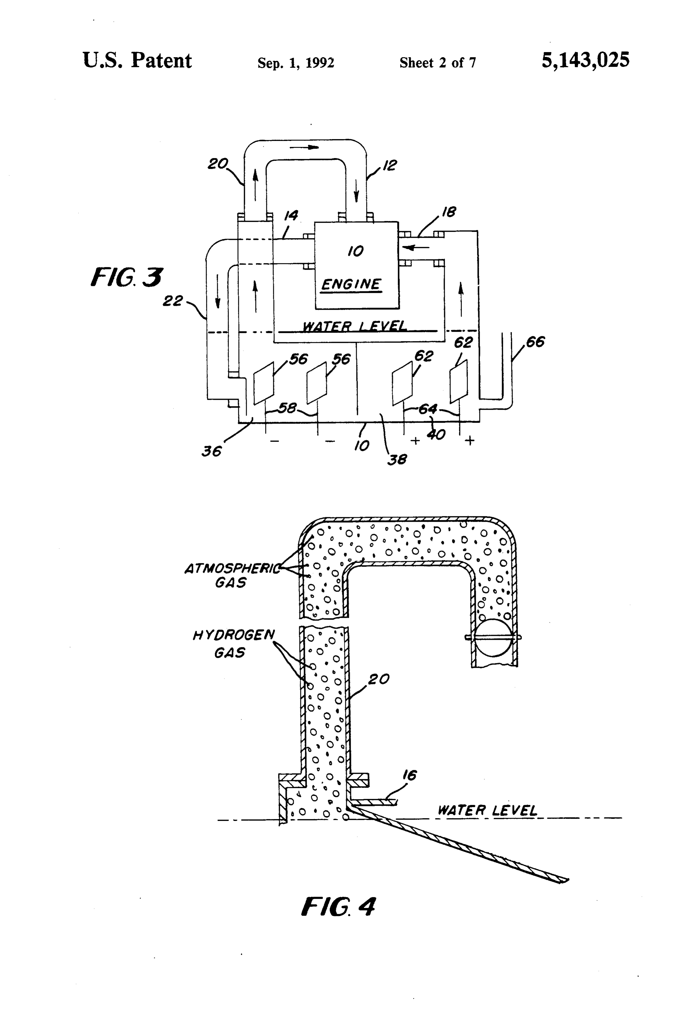
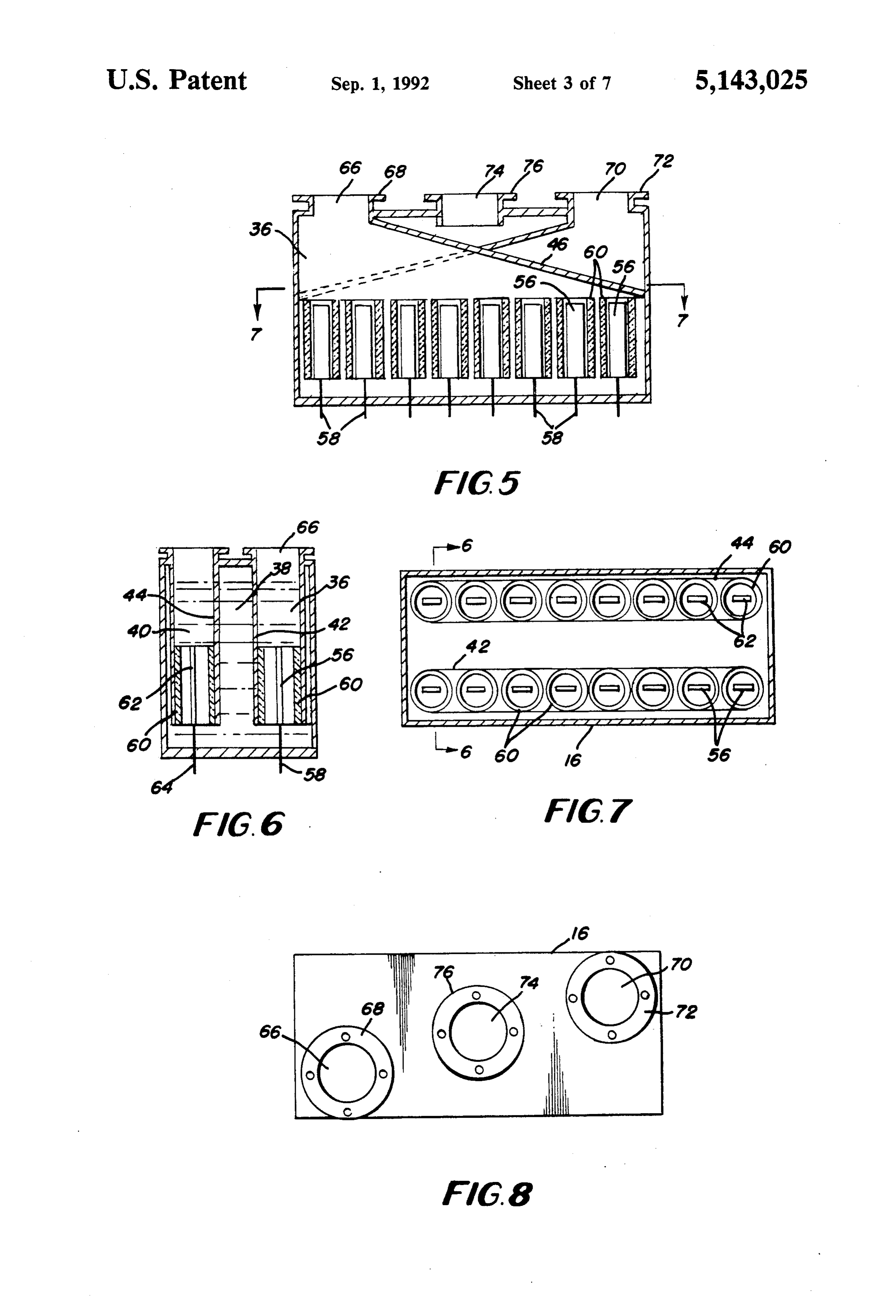
FIG. 16 is a schematic of an electrical system for FIG. 3 is a schematic of internal combustion engine controlling the production of fuel of the invention. 10 and fuel production tank 16. The production tank 16 FIG. 17 is an open centrifugal switch of the inven is divided into hydrogen and oxygen production com tion. partments 36 and 40, respectively. There is a divider 57 FIG. 17A is a top view of FIG. 17. 40 separating the compartments 36 and 40. In this figure FIG. 17B is a side view of a closed centrifugal switch there is no center compartment 38 as in FIG. 2, instead of the invention. exhaust gases are pumped into compartment 36. Fresh FIG. 17C is a top view of FIG. 17B. water is added via fill pipe 66 into compartment 40. FIG. 18 is a cross sectional view of an impact switch There are cathodes 56 in compartment 36, and anodes of the invention. 45 62 in compartment 40.
DESCRIPTION OF THE INVENTION
Hydrogen inlet 20 and oxygen inlet 18 empty into the engine intake manifold. Hydrogen and oxygen gases
Referring to the drawings there is shown in FIG. 1 an produced in the tank 16, leave the respective compart internal combustion engine 10 connected by an intake ments 36 and 40 separately and co-mix either in the manifold 12 and an exhaust manifold 14 to a fuel tank 50 intake manifold or in the engine cylinders. Exhaust 16. An oxygen gas inlet manifold 18 carries oxygen gas gases are carried to compartment 36 via tube 22. to the inlet manifold 12. Hydrogen gas inlet manifold 20 FIGS. 5-8 show the fuel production tank 16 having also carries gas to the inlet manifold 12. The two gases, three compartments, 36 (for hydrogen production), 40 hydrogen and oxygen, are mixed together just before (for oxygen production), and 38 (for receiving fresh entering the inlet manifold to prevent any flash back. 55 water and exhaust gases and water vapor). FIGS. 6 and Exhaust gases are moved from the engine 10 through 7 show the three compartments best, where in FIG. 6 manifold 14 and exhaust tube 22 which empties into the the lower ends of the dividers 42 and 44 are shown fuel tank 16. above the bottom of tank 16 and the water flow is In FIG. 2 the feeding of fuel to the engine 10 is better shown moving down through middle compartment 38 understood. Oxygen is removed from the fuel tank 16 60 and spreading out into compartments 36 and 40. In and carried to a vertical mixing or combining manifold FIGS. 6 and 7, the cathodes 56 and anodes 62 are sur 24. Hydrogen is similarly removed from the fuel tank 16 rounded by an insulated cylinder 60, such as glass, and and carried to the mixing manifold 24 which has an are connected by electrical leads 58 and 64, respec opening 25 to the intake manifold 12 separate inlet pipes tively, to a source of electricity. 18 and 20 where the two gases are combined before 65 FIG. 5 shows the bank of cathodes 56 surrounded by entering the manifold 12 by. A single cylinder 26 and a cylinders 60 and connected to electrical leads 58. The reciprocating piston 28 represent an internal combus leads 58 and 64 project through the bottom of the tank tion engine. The fuel gases are forced into the cylinder 16 to connect to a source of electricity, which will be
Page 11
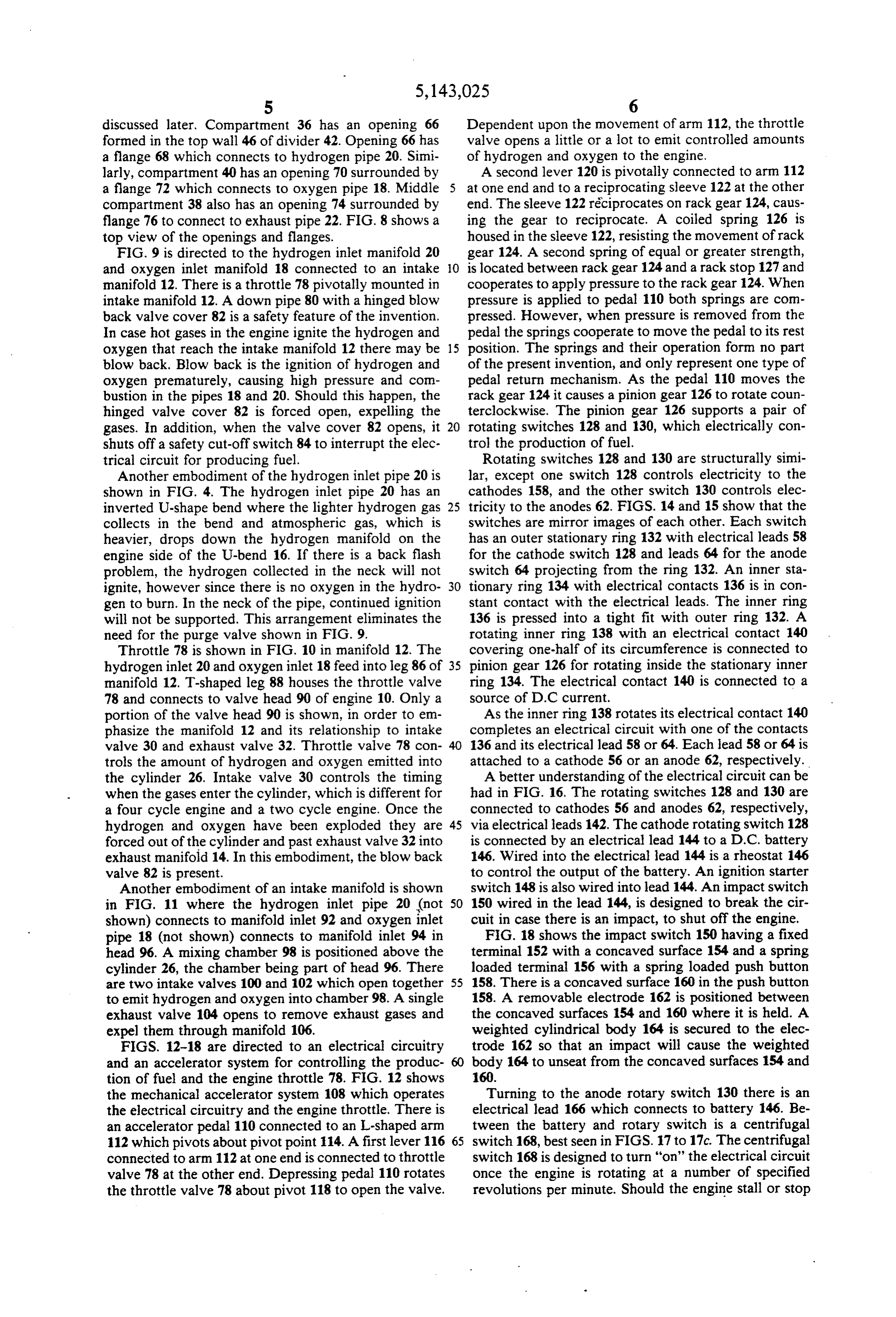
discussed later. Compartment 36 has an opening 66 Dependent upon the movement of arm 112, the throttle formed in the top wall 46 of divider 42. Opening 66 has valve opens a little or a lot to emit controlled amounts a flange 68 which connects to hydrogen pipe 20. Simi of hydrogen and oxygen to the engine. larly, compartment 40 has an opening 70 surrounded by A second lever 120 is pivotally connected to arm 112 a flange 72 which connects to oxygen pipe 18. Middle at one end and to a reciprocating sleeve 122 at the other compartment 38 also has an opening 74 surrounded by end. The sleeve 122 reciprocates on rack gear 124, caus flange 76 to connect to exhaust pipe 22. FIG. 8 shows a ing the gear to reciprocate. A coiled spring 126 is top view of the openings and flanges. housed in the sleeve 122, resisting the movement of rack FIG. 9 is directed to the hydrogen inlet manifold 20 gear 124. A second spring of equal or greater strength, and oxygen inlet manifold 18 connected to an intake O is located between rack gear 124 and a rack stop 127 and manifold 12. There is a throttle 78 pivotally mounted in cooperates to apply pressure to the rack gear 124. When intake manifold 12. A down pipe 80 with a hinged blow pressure is applied to pedal 110 both springs are com back valve cover 82 is a safety feature of the invention. pressed. However, when pressure is removed from the In case hot gases in the engine ignite the hydrogen and pedal the springs cooperate to move the pedal to its rest oxygen that reach the intake manifold 12 there may be 15 position. The springs and their operation form no part blow back. Blow back is the ignition of hydrogen and of the present invention, and only represent one type of oxygen prematurely, causing high pressure and con pedal return mechanism. As the pedal 110 moves the bustion in the pipes 18 and 20. Should this happen, the rack gear 124 it causes a pinion gear 126 to rotate coun hinged valve cover 82 is forced open, expelling the terclockwise. The pinion gear 126 supports a pair of gases. In addition, when the valve cover 82 opens, it 20 rotating switches 128 and 130, which electrically con shuts off a safety cut-off switch 84 to interrupt the elec trol the production of fuel.
trical circuit for producing fuel. Rotating switches 128 and 130 are structurally simi Another embodiment of the hydrogen inlet pipe 20 is lar, except one switch 128 controls electricity to the shown in FIG. 4. The hydrogen inlet pipe 20 has an cathodes 158, and the other switch 130 controls elec inverted U-shape bend where the lighter hydrogen gas 25 tricity to the anodes 62. FIGS. 14 and 15 show that the collects in the bend and atmospheric gas, which is switches are mirror images of each other. Each switch heavier, drops down the hydrogen manifold on the has an outer stationary ring 132 with electrical leads 58 engine side of the U-bend 16. If there is a back flash for the cathode switch 128 and leads 64 for the anode problem, the hydrogen collected in the neck will not switch 64 projecting from the ring 132. An inner sta ignite, however since there is no oxygen in the hydro 30 tionary ring 134 with electrical contacts 136 is in con gen to burn. In the neck of the pipe, continued ignition stant contact with the electrical leads. The inner ring will not be supported. This arrangement eliminates the 136 is pressed into a tight fit with outer ring 132. A need for the purge valve shown in FIG. 9. rotating inner ring 138 with an electrical contact 140 Throttle 78 is shown in FIG. 10 in manifold 12. The covering one-half of its circumference is connected to hydrogen inlet 20 and oxygen inlet 18 feed into leg 86 of 35 pinion gear 126 for rotating inside the stationary inner manifold 12. T-shaped leg 88 houses the throttle valve ring 134. The electrical contact 140 is connected to a 78 and connects to valve head 90 of engine 10. Only a source of D.C current.
portion of the valve head 90 is shown, in order to em As the inner ring 138 rotates its electrical contact 140 phasize the manifold 12 and its relationship to intake completes an electrical circuit with one of the contacts valve 30 and exhaust valve 32. Throttle valve 78 con 136 and its electrical lead 58 or 64. Each lead 58 or 64 is trols the amount of hydrogen and oxygen emitted into attached to a cathode 56 or an anode 62, respectively. the cylinder 26. Intake valve 30 controls the timing A better understanding of the electrical circuit can be when the gases enter the cylinder, which is different for had in FIG. 16. The rotating switches 128 and 130 are a four cycle engine and a two cycle engine. Once the connected to cathodes 56 and anodes 62, respectively, hydrogen and oxygen have been exploded they are 45 via electrical leads 142. The cathode rotating switch 128 forced out of the cylinder and past exhaust valve 32 into is connected by an electrical lead 144 to a D.C. battery exhaust manifold 14. In this embodiment, the blow back 146. Wired into the electrical lead 144 is a rheostat 146 valve 82 is present. to control the output of the battery. An ignition starter Another embodiment of an intake manifold is shown switch 148 is also wired into lead 144. An impact switch in FIG. 11 where the hydrogen inlet pipe 20 (not 50 150 wired in the lead 144, is designed to break the cir shown) connects to manifold inlet 92 and oxygen inlet cuit in case there is an impact, to shut off the engine. pipe 18 (not shown) connects to manifold inlet 94 in FIG. 18 shows the impact switch 150 having a fixed head 96. A mixing chamber 98 is positioned above the terminal 152 with a concaved surface 154 and a spring cylinder 26, the chamber being part of head 96. There loaded terminal 156 with a spring loaded push button are two intake valves 100 and 102 which open together 55 158. There is a concaved surface 160 in the push button to emit hydrogen and oxygen into chamber 98. A single 158. A removable electrode 162 is positioned between exhaust valve 104 opens to remove exhaust gases and the concaved surfaces 154 and 160 where it is held. A expel them through manifold 106. weighted cylindrical body 164 is secured to the elec FIGS. 12-18 are directed to an electrical circuitry trode 162 so that an impact will cause the weighted and an accelerator system for controlling the produc body 164 to unseat from the concaved surfaces 154 and tion of fuel and the engine throttle 78. FIG. 12 shows 160.
the mechanical accelerator system 108 which operates Turning to the anode rotary switch 130 there is an the electrical circuitry and the engine throttle. There is electrical lead 166 which connects to battery 146. Be an accelerator pedal 110 connected to an L-shaped arm tween the battery and rotary switch is a centrifugal 112 which pivots about pivot point 114. A first lever 116 65 switch 168, best seen in FIGS. 17 to 17c. The centrifugal connected to arm 112 at one end is connected to throttle switch 168 is designed to turn "on" the electrical circuit valve 78 at the other end. Depressing pedal 110 rotates once the engine is rotating at a number of specified the throttle valve 78 about pivot 118 to open the valve. revolutions per minute. Should the engine stall or stop
Page 12
rotating, the electrical circuit would be switched off, bottom of the inverted U-shape bend on the engine side stopping any further manufacture of oxygen and hydro of said bend.
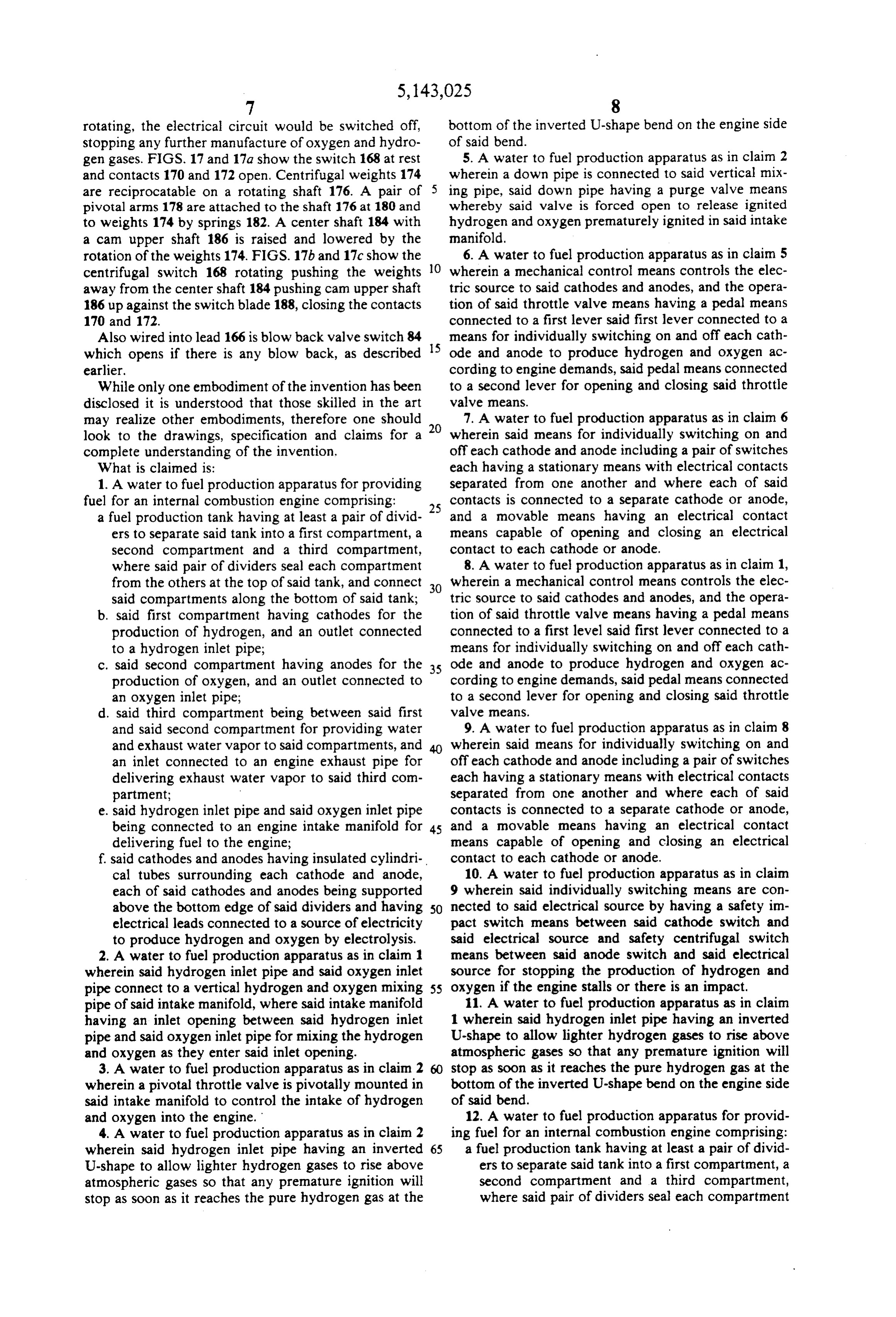
gen gases. FIGS. 17 and 17a show the switch 168 at rest 5. A water to fuel production apparatus as in claim 2 and contacts 170 and 172 open. Centrifugal weights 174 wherein a down pipe is connected to said vertical mix are reciprocatable on a rotating shaft 176. A pair of 5 ing pipe, said down pipe having a purge valve means pivotal arms 178 are attached to the shaft 176 at 180 and whereby said valve is forced open to release ignited to weights 174 by springs 182. A center shaft 184 with hydrogen and oxygen prematurely ignited in said intake a cam upper shaft 186 is raised and lowered by the manifold.
rotation of the weights 174. FIGS. 17b and 17c show the O 6. A water to fuel production apparatus as in claim 5 centrifugal switch 168 rotating pushing the weights wherein a mechanical control means controls the elec away from the center shaft 184 pushing cam upper shaft tric source to said cathodes and anodes, and the opera 186 up against the switch blade 188, closing the contacts tion of said throttle valve means having a pedal means 170 and 172. connected to a first lever said first lever connected to a Also wired into lead 166 is blow back valve switch 84means for individually switching on and off each cath which opens if there is any blow back, as described 15 ode and anode to produce hydrogen and oxygen ac earlier. cording to engine demands, said pedal means connected While only one embodiment of the invention has been to a second lever for opening and closing said throttle disclosed it is understood that those skilled in the art valve means.
may realize other embodiments, therefore one should 7. A water to fuel production apparatus as in claim 6 look to the drawings, specification and claims for a 20 wherein said means for individually switching on and complete understanding of the invention. off each cathode and anode including a pair of switches What is claimed is: each having a stationary means with electrical contacts 1. A water to fuel production apparatus for providing separated from one another and where each of said fuel for an internal combustion engine comprising: contacts is connected to a separate cathode or anode, a fuel production tank having at least a pair of divid 25 and a movable means having an electrical contact ers to separate said tank into a first compartment, a means capable of opening and closing an electrical second compartment and a third compartment, contact to each cathode or anode.
where said pair of dividers seal each compartment 8. A water to fuel production apparatus as in claim 1, from the others at the top of said tank, and connect 30 wherein a mechanical control means controls the elec said compartments along the bottom of said tank; tric source to said cathodes and anodes, and the opera b. said first compartment having cathodes for the tion of said throttle valve means having a pedal means production of hydrogen, and an outlet connected connected to a first level said first lever connected to a to a hydrogen inlet pipe; means for individually switching on and off each cath c. said second compartment having anodes for the 35 ode and anode to produce hydrogen and oxygen ac production of oxygen, and an outlet connected to cording to engine demands, said pedal means connected an oxygen inlet pipe; to a second lever for opening and closing said throttle d. said third compartment being between said first valve means.
and said second compartment for providing water 9. A water to fuel production apparatus as in claim 8 and exhaust water vapor to said compartments, and wherein said means for individually switching on and an inlet connected to an engine exhaust pipe for off each cathode and anode including a pair of switches delivering exhaust water vapor to said third com each having a stationary means with electrical contacts partment; separated from one another and where each of said e. said hydrogen inlet pipe and said oxygen inlet pipe contacts is connected to a separate cathode or anode, being connected to an engine intake manifold for 45 and a movable means having an electrical contact delivering fuel to the engine; means capable of opening and closing an electrical f said cathodes and anodes having insulated cylindri contact to each cathode or anode.
cal tubes surrounding each cathode and anode, 10. A water to fuel production apparatus as in claim each of said cathodes and anodes being supported 9 wherein said individually switching means are con above the bottom edge of said dividers and having 50 nected to said electrical source by having a safety im electrical leads connected to a source of electricity pact switch means between said cathode switch and to produce hydrogen and oxygen by electrolysis. said electrical source and safety centrifugal switch 2. A water to fuel production apparatus as in claim 1 means between said anode switch and said electrical wherein said hydrogen inlet pipe and said oxygen inlet source for stopping the production of hydrogen and pipe connect to a vertical hydrogen and oxygen mixing 55 oxygen if the engine stalls or there is an impact. pipe of said intake manifold, where said intake manifold 11. A water to fuel production apparatus as in claim having an inlet opening between said hydrogen inlet 1 wherein said hydrogen inlet pipe having an inverted pipe and said oxygen inlet pipe for mixing the hydrogen U-shape to allow lighter hydrogen gases to rise above and oxygen as they enter said inlet opening. atmospheric gases so that any premature ignition will 3. A water to fuel production apparatus as in claim 2 stop as soon as it reaches the pure hydrogen gas at the wherein a pivotal throttle valve is pivotally mounted in bottom of the inverted U-shape bend on the engine side said intake manifold to control the intake of hydrogen of said bend.
and oxygen into the engine. 12. A water to fuel production apparatus for provid 4. A water to fuel production apparatus as in claim 2 ing fuel for an internal combustion engine comprising: wherein said hydrogen inlet pipe having an inverted 65 a fuel production tank having at least a pair of divid U-shape to allow lighter hydrogen gases to rise above ers to separate said tank into a first compartment, a atmospheric gases so that any premature ignition will second compartment and a third compartment, stop as soon as it reaches the pure hydrogen gas at the where said pair of dividers seal each compartment
Page 13
from the others at the top of said tank, and connect off each cathode and anode including a pair of switches said compartments along the bottom of said tank; each having a stationary means with electrical contacts b. said first compartment having cathodes for the separated from one another and where each of said production of hydrogen, and an outlet connected contacts is connected to a separate cathode or anode, to a hydrogen inlet pipe; and a movable means having an electrical contact c. said second compartment having anodes for the means capable of opening and closing an electrical production of oxygen, and an outlet connected to contact to each cathode or anode.
an oxygen inlet pipe; 15. A water to fuel production apparatus as in claim d. said third compartment being between said first 12 wherein a mechanical control means controls the and said second compartment for providing water O electric source to said cathodes and anodes, and the and exhaust water vapor to said compartments, and operation of said throttle valve means having a pedal an inlet connected to an engine exhaust pipe for means connected to a first lever and said first lever is delivering exhaust water vapor to said third com connected to a means for individually switching on and partment; off each cathode and anode to produce hydrogen and e, said hydrogen inlet pipe and said oxygen inlet pipe 5 oxygen according to engine demands, said pedal means being separately connected to a mixing chamber in is connected to a second lever for opening and closing a valve head of an internal combustion engine for said throttle valve means.
delivering fuel to the engine; 16. A water to fuel production apparatus as in claim f, said cathodes and anodes having insulated cylindri 15 where said means for individually switching on and cal tubes surrounding each cathode and anode, 20 off each cathode and each of said cathodes and anodes being supported each having a stationary meansanode includes a pair of switches above the bottom edge of said dividers and having with electrical contacts electrical leads connected to a source of electricity separated from one another and where each of said to produce hydrogen and oxygen by electrolysis. contacts is connected to a separate cathode or anode, 13. A water to fuel production apparatus as in claim 25 and a movable means having an electrical contact 12 wherein a mechanical control means controls the means capable of opening and closing an electrical electric source to said cathodes and anodes, and the contact to each cathode or anode. operation of said throttle valve means having a pedal 17. A water to fuel production apparatus as in claim means connected to a first lever said first lever con 16 wherein said individually switching means are con nected to a means for individually switching on and off 30 nected to said electrical source by having a safety im each cathode and anode to produce hydrogen and oxy pact switch means between said cathode switch and gen according to engine demands, said pedal means said electrical source and safety centrifugal switch connected to a second lever for opening and closing means between said anode switch and said electrical said throttle valve means. source for stopping the production of hydrogen and 14. A water to fuel production apparatus as in claim 35 oxygen if the enginek stalls ork there is an impact. 13 wherein said means for individually switching on and sk k s
Provenance
- Collection
- Cited prior art
- Original PDF
- patentimages.storage.googleapis.com →
- Filed
- 1991-01-25
- Pages
- 13
- Method
- pdftotext (the PDF's own text layer) + pdftoppm 300dpi page scans
- Source
- Google Patents bibliographic record
- Granted
- 1992-09-01
- Inventors
- John F. Munday
- Transcribed from
- patentimages.storage.googleapis.com →