patent · US4209303
Method and apparatus for recovery of combustible gas from waste
24 June 1980
Page 1 — bibliographic record
United States Patent 19 11 4,209,303 Ricks 45 Jun. 24, 1980 (54) METHOD AND APPARATUS FOR 3,338,826 8/1967 Kramer .................................. 210/12 RECOVERY OF COMBUSTIBLE GAS FROM 3,973,043 8/1976 . Lynn ...................................... 195/27 WASTE 4,050,907 9/1977 Brimhall . ... 48/197 A 4,053,395 10/1977 Switzgable ............................. 210/12 76 Inventor: Jay W. Ricks, 4121 Cambridge Dr., FOREIGN PATENT DOCUMENTS Bakersfield, Calif. 93306 1528932 5/1967 France ..................................... 29/31
22) Filed: Sep. 8, 1978 Primary Examiner-S. Leon Bashore
Assistant Examiner-Michael Goldman (51) Int. Cl’................................................ C10, 3/00 Attorney, Agent, or Firm-Clarence A. O'Brien; Harvey (52) U.S. C. ........................................ 48/111; 48/209; B. Jacobson 435/166; 435/316; 98/115 R; 219/311; 57 ABSTRACT
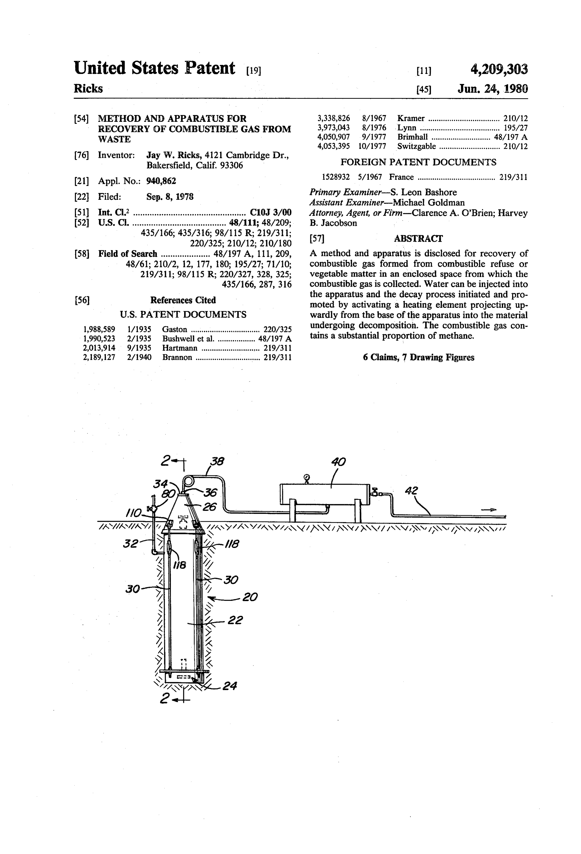
(58) Field of Search ..................... 48/197 A, 111, 209, A method and apparatus is disclosed for recovery of 48/61; 210/2, 12, 177, 180; 195/27; 71/10; combustible gas formed from combustible refuse or 219/311; 98/115 R; 220/327, 328, 325; vegetable matter in an enclosed space from which the 435/166,287, 316 combustible gas is collected. Water can be injected into 56) References Cited the apparatus and the decay process initiated and pro moted by activating a heating element projecting up
1,988,589 1/1935 Gaston ................................. 220/325 undergoing decomposition. The combustible gas con 1990,523 2/1935 Bushwell et al ... 48/197 A tains a substantial proportion of methane. 2,013,914 9/1935 Hartmann ...... a 219/311 2,189,127 2/1940 Brannon .............................. 219/311 6 Claims, 7 Drawing Figures
Page 2
Drawing sheet — no readable text.
Page 3
Drawing sheet — no readable text.
Page 4
refuse, which would otherwise present a solid waste
METHOD AND APPARATUS FOR RECOVERY OF disposal problem.
COMBUSTIBLE GAS FROM WASTE Another object of the invention is to provide a method and apparatus for production of combustible
BACKGROUND OF THE INVENTION 5 gas useful for cooking, lighting, heating, or other pur poses.
1. Field of the Invention
The invention relates to apparatus and a method for fanStill another object of the invention is to provide a operating the apparatus whereby combustible gas useful and assembly for efficient collection of combustible gas, for cooking, lighting, heating, or other purposes can be 10 sition of waste aorganic producing slightly reduced pressure for decompo refuse.
formed by decomposition of combustible refuse or veg etable matter. Collecting means is provided for collect apparatus for treatment ofthelarge
Yet another object of invention is to provide an ing combustible gas produced, including a substantial ble refuse by apparatus which isquantities of combusti relatively unobtrusive proportion of methane. Means for injecting water, and and therefore adaptable for use in municipal or residen means for heating the material undergoing decomposi 5 tial locations.
tion are provided. A further object of the invention is to provide an 2. Description of the Prior Art apparatus which is usable during all seasons in temper Methods to produce methane from organic waste ate regions such as exist in the United States. materials, sewage sludge, woody material, greases, and Still a further object of the invention is to provide a other wastes are known. For example, Teichmann et all 20 waste disposal apparatus which when placed in opera in U.S. Pat. No. 3,671,209, issued June 20, 1972, add a tion requires minimum supervision, little maintenance, fluid such as water to bits of garbage or solid waste and is characterized by simplicity of design and con matter to produce a pumpable feed mixture stream, struction.
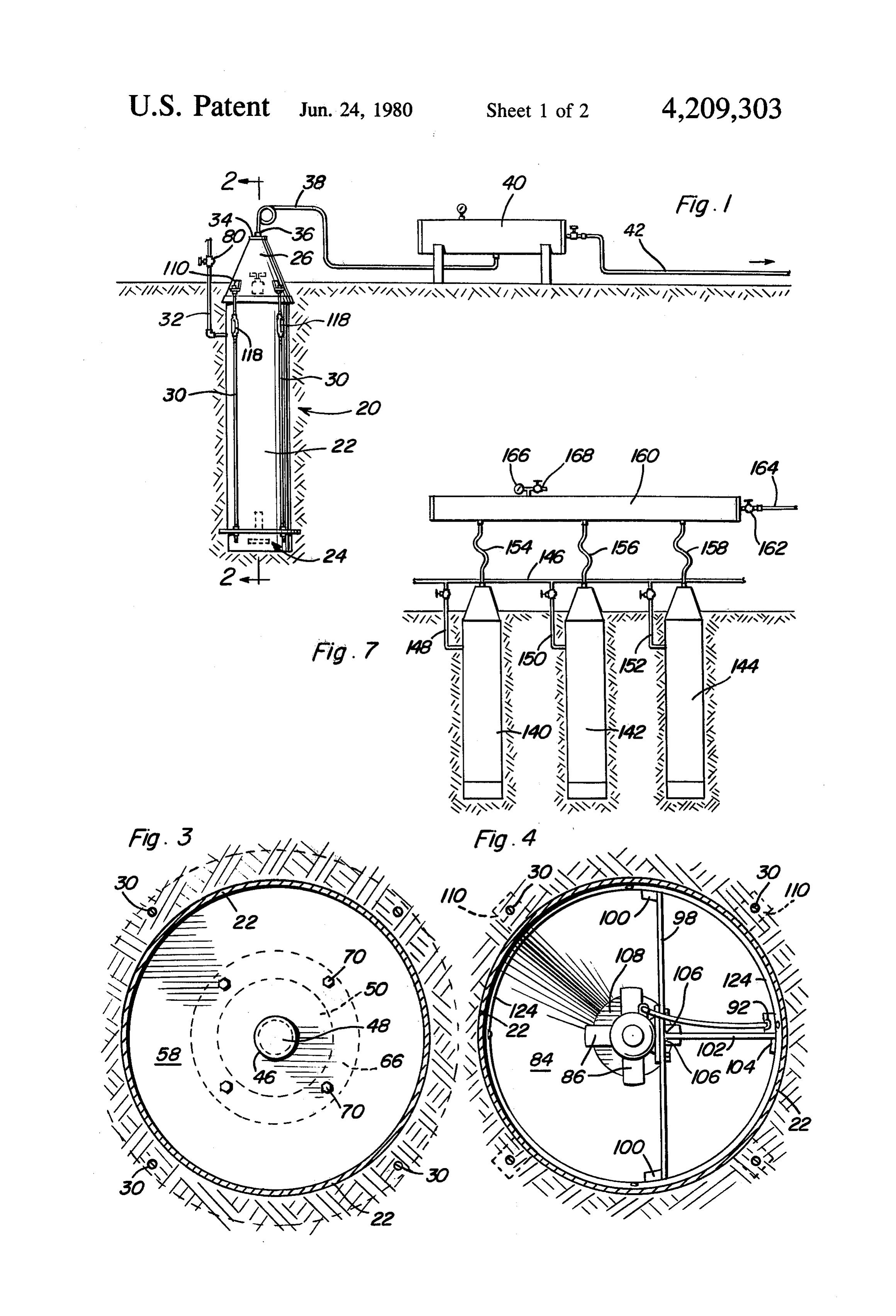
which can be preheated and reacted by partial oxidation Yet a further object of the invention is to provide a with a stream of oxygen-rich gas to produce a stream of 25 waste disposal apparatus which does not require enclo synthesis gas, fuel gas, and other materials. sure within a building or other structure. Buswell et al in U.S. Pat. No. 1,990,523, issued Feb. These together with other objects and advantages 12, 1935, produce methane by controlled bacterial de which will become subsequently apparent reside in the composition of cellulosic material such as cornstalks by details of construction and operation as more fully here controlled and regulated bacterial action. 30 inafter described and claimed, reference being had to Switzgable in U.S. Pat. No. 4,053,395, issued Oct. 11, the accompanying drawings forming a part hereof, 1977, utilizes a plurality of airtight tanks for processing wherein like numerals refer to like parts throughout. a slurry of biodegradable waste materials, one of the BRIEF DESCRIPTION OF THE DRAWINGS tanks being provided with a cathode and another with 35 an anode for conducting electrolysis reactions to pro FIG. 1 is a schematic view of the single unit of the duce hydrogen, which can further react to produce invention, showing its association with a collecting or receiving tank for gas produced during operation.
methane.
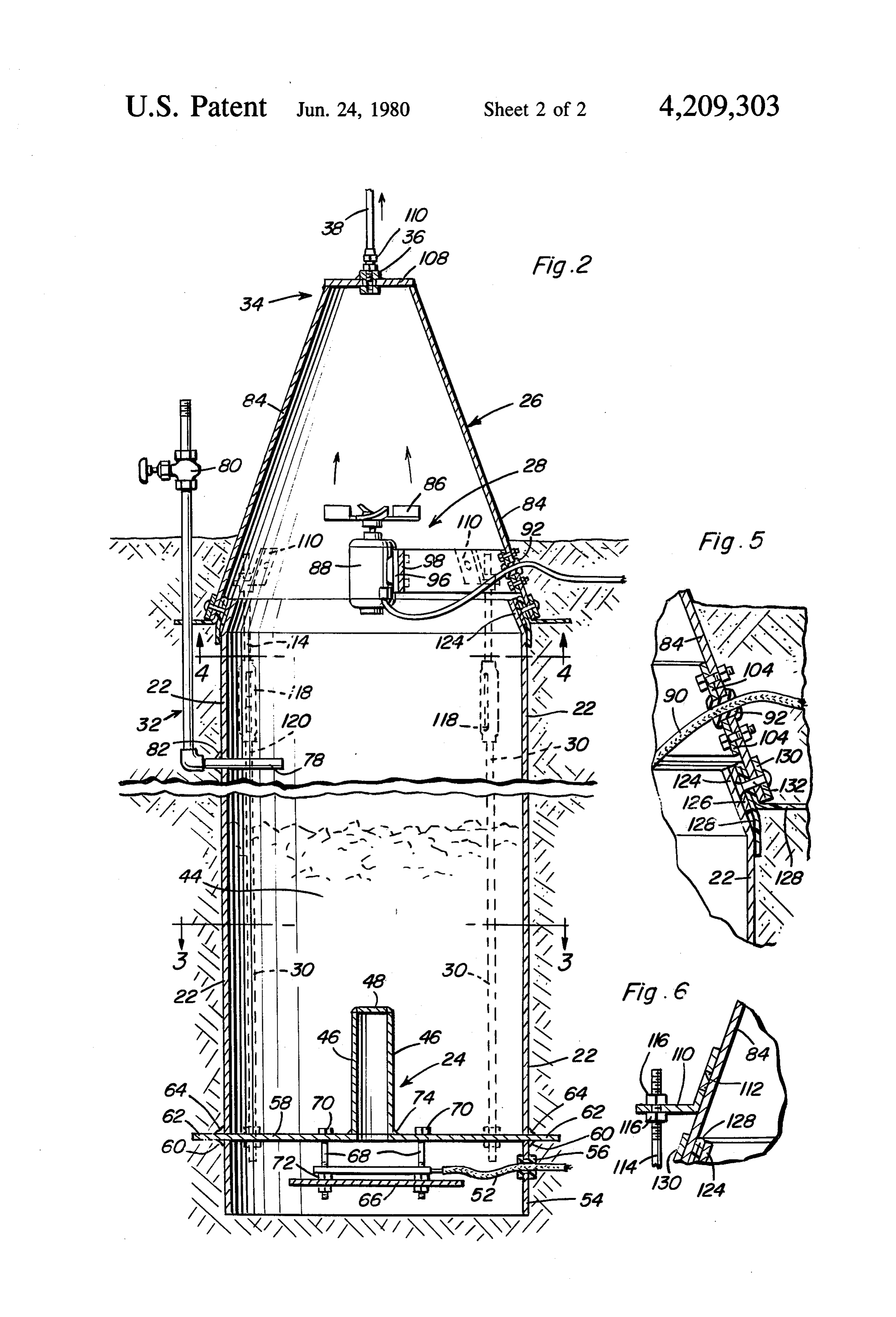
Other patents showing production of methane in ratus, FIG. 2 is a sectional view of the gas generating appa treatment of sewage sludge or other organic waste ma sectiontaken line substantially upon a plane passing along
terials include the following: FIG. 3 is a top sectional view looking downwardly U.S. Pat. No. 1,717,100 -J. W. Downes-June 11, upon a plane passing along section line 3-3 on FIG. 2.
FIG. 4 is a tranverse sectional view taken substan
U.S. Pat. No. 3,368,967-T. O. Weaver et al-Feb. 13, tially upon a plane passing along section line 4-4 on
U.S. Pat. No. 3,687,646-A. Brent et al-Aug. 29, FIG. 2, viewed upwardly to show details of the fan
1972 assembly.
U.S. Pat. No. 4,057,401-O. W. Boblitz-Nov. 8, theFIG. joint 5 is a fragmentary enlarged sectional view of between the cone assembly and the tank, show
ing details of the airtight seal for retention of gas inside
SUMMARY OF THE INVENTION 50 the apparatus.
The invention provides an upright airtight tank with mounting FIG. 6 is a fragmentary enlarged sectional view of a a conical cap placed over the tank and joined to it near ing also thebracket upper attached to the cone assembly, show portion of an associated tie rod.
or at ground level. A heating assembly is provided at FIG. 7 is a schematic representation of a plurality of the bottom of the tank with transfer of heat into the tank 55 gas generating units attached in parallel to a collecting contents facilitated by an upward projection into com reservoir.
bustible refuse contained therein. Water can be control lably injected into the refuse contained within the tank DESCRIPTION OF THE PREFERRED from a line entering the tank from the outside. Collec EMBODIMENT tion of gas produced during decay and decomposition The device of the present invention for generation of of the organic matter is facilitated by a fan assembly at combustible gas from refuse is indicated generally by the base of the cone to force evolved gas upwardly the numeral 20 in FIG. 1, and comprises tank 22, heater toward the nose of the cone, where the gas exits into a assembly 24, located in the lower portion of tank 22, line leading to a holding reservoir for ultimate dispo cone assembly 26, and fan assembly 28, located near the sition. A plurality of units can be arranged in parallel for 65 base of cone assembly 26. Cone assembly 26 is detach simultaneous operation. able from tank 22 near its base for addition and replen Accordingly, it is an object of the invention to pro ishing of a supply of solid waste matter into tank 22, and vide a method and apparatus for disposal of combustible is tightenable thereon by tie rods 30. Tank 22 and the

Page 5
lower portion of cone assembly 28 are located below plate 108, and is threaded to receive angle bracket 110 grade in order to minimize potential nuisance problems for connecting with pipe line 38. Operation of fan as to facilitate loading of combustible material into tank 22 sembly 28 serves to keep the interior of tank 22 under and to prevent freezing during winter months if outside slightly reduced pressure, and, further, to help prevent temperatures fall below 0 degrees C. Water inlet line 32 5 accumulation of gases which are heavier than air, such permits regulated injection of water into tank 22. Nose as carbon dioxide, in tank 22.
34 of cone assembly 26 is provided with an attachment The mechanism for assembly of cone assembly 26 and 36 for withdrawal of gas from inside nose 34 through tank 22 is best illustrated in FIGS. 5 and 6, where angle pipeline 38, which carries gas to storage reservoir 40 for bracket 110 is shown welded to cone 84 at plug weld ultimate disposition through line 42. 10 112. Upper segment 114 of tie rod 30 is held to angle Referring to FIG. 2, device 20 is shown in greater bracket 110 by double nuts 116 for adjustable spacing of detail. Combustible refuse 44 fills the lower portion of upper segment 114 longitudinally. Each of turnbuckles tank 22 and absorbs heat from heater assembly 24 pri 118 permits tightening of upper segment 114 longitudi marily by conduction from heater pipe 46, which is of nally with respect to lower segment 120 as cone assem sufficient diameter and height to allow the desired de- 15 bly 26 is compressed downwardly upon neck 124 at the gree of heating to be furnished by conduction into the upper end of tank 22. During downward compression interior of the mass 44 of combustible refuse. Although of cone assembly 26, support band 126 compresses neck the applicant does not wish to limit the utility of the 124 to provide a substantially leak-free joint. Plastic present invention to specific dimensional characteris strip 128, which can be polyethylene, further assists in tics, since many sizes and shapes are useful and opera 20 preventing escape of gases from within the apparatus. ble, one possible construction of pipe 46 might have a Support band 130 provides the gripping surface for the diameter of about six inches, and a height of about head of pop rivet 132, which holds the entire assembly twenty inches. Pipe 46 is sealingly capped with plate 48, at the base of cone 84 together for lowering on neck 124 welded about its periphery to pipe 46. Heating of the during assembly. Adjustment of turnbuckles 118 per interior of pipe 46 is carried out by the provision of 25 mits uniform pressure to be applied between band 126 heating element 50, most conveniently a resistance and neck 24, after which operation can commence. heater element powered from a 110 volt power supply FIG. 7 shows a plurality of the generating devices of connected through asbestos insulated wire 52 to a the present invention, designated by the numerals 140, source of power outside device 10. Wire 52 passes 142 and 144. Water inlet line 146 permits individually through heaterhood 54 at grommet 56. Base plate 58 is 30 controllable injection of water through inlets 148, 150 welded to heater hood 54 at weldment 60, the outward and 152. Gas outlet lines 154, 156 and 158 lead to stor extensions 62 of base plate 58 forming supports for en age manifold 160, and shut-off valve 162 permits with gagement of the lower ends of tie rods 30. Tank 22 rests drawal of gas through outlet line 164, with pressure and is welded upon base plate 58 at weldment 64. gauge 166 and relief valve 168, which can be conve Heater element 50 is dependingly held beneath base niently set at about 60 pounds per square inch, also plate 58, resting upon heating unit support 66 by an included on manifold reservoir 160.
appropriate insulator 68. Support 66 is heid by bolts 68, Although the drawings show the apparatus situated which pass through base plate 58 at sealed heads 70, and primarily underground, with soil covering all but the which hold heating unit support 66 by double nuts 72 upper portion of come assembly 26, it is to be under for adjustment of the distance between base plate 58 and stood that it is necessary to remove soil from the vicin heating element 50. A tight seal between pipe 46 and ity of the lower part of cone assembly 26 in order to base plate 58 is guaranteed by weldment 74; conse gain access to turnbuckles 118 and removal of cone quently, passage of gaseous and liquid materials is pre assembly 26. Accordingly, clearance space between the vented from the interior of tank 22, while passage of ground and tank 22, as well as the lower part of cone heat into the interior of pipe 46 and thence into the mass 45 assembly 26, could be necessary to provide access for 44 of refuse contained in tank 22 is possible. Water can installation, maintenance, inspection or other purposes. be controllably injected into tank 22 through water Moreover, a layer of insulation surrounding tank 22 can injection assembly 32 at inlet 78 by opening valve 80. be provided to retain heat as the contents undergo Sealing grommet 82 insures an airtight seal between the decay and decomposition.
interior of tank 22 and the outside. SO In operation, with cone assembly 26 detached from Fan assembly 28, located near the bottom of cone tank 22, combustible refuse is loaded to the desired level assembly 26, forces gas evolved by decomposition of in tank 22. Cone assembly. 26 is then placed on neck 24 the mass of refuse 44 upwardly toward nose 34 of cone of tank 22 with brackets 110 in proper alignment over 84, as indicated by the arrows in FIG. 2. Fan assembly the lower portion 120 of tie rods 30. Double nuts 116 are 28 comprises conventional fan blades 86 rotatably con- 55 adjusted to permit tightening of turnbuckles 118. After nected to fan motor 88, which is constructed from com a close fit between support band 126 and neck 124 has ponents which prevent ignition of any surrounding been achieved by tightening of turnbuckles 118, a suit combustible mixture of gases. Such spark-free explo able quantity of water is injected through inlet 78 by sion-proof motors are well known in the art. Fan motor opening valve 80, and valve 80 is closed. Activation of 88 is powered by asbestos insulated wire 90, passing 60 heating element 50 begins the decay process of mass 44 through grommet 92 in cone 84. Motor mount 96 is of refuse, and methane is liberated. After a quantity of bolted to motor support beam 98, which extends to methane has been liberated sufficient to displace air opposite sides of cone 84 for fastening near the base by contained above refuse 24, fan assembly 28 is turned on brackets 100. Further support is obtained from motor to direct methane upwardly through pipeline 38 under a support 102, attached at bracket 104 to cone 84. Support 65 slight positive pressure, leaving refuse 44 under a slight beam 98 is welded to support 102 at weldments 106. negative pressure. The process is continued until de Nose plate 108 is welded to come 84 at nose 34 of cone composition of the supply of refuse 44 has been substan assembly 26. Connector 36 is in turn welded to nose tially completed, and the process can be repeated by
Page 6
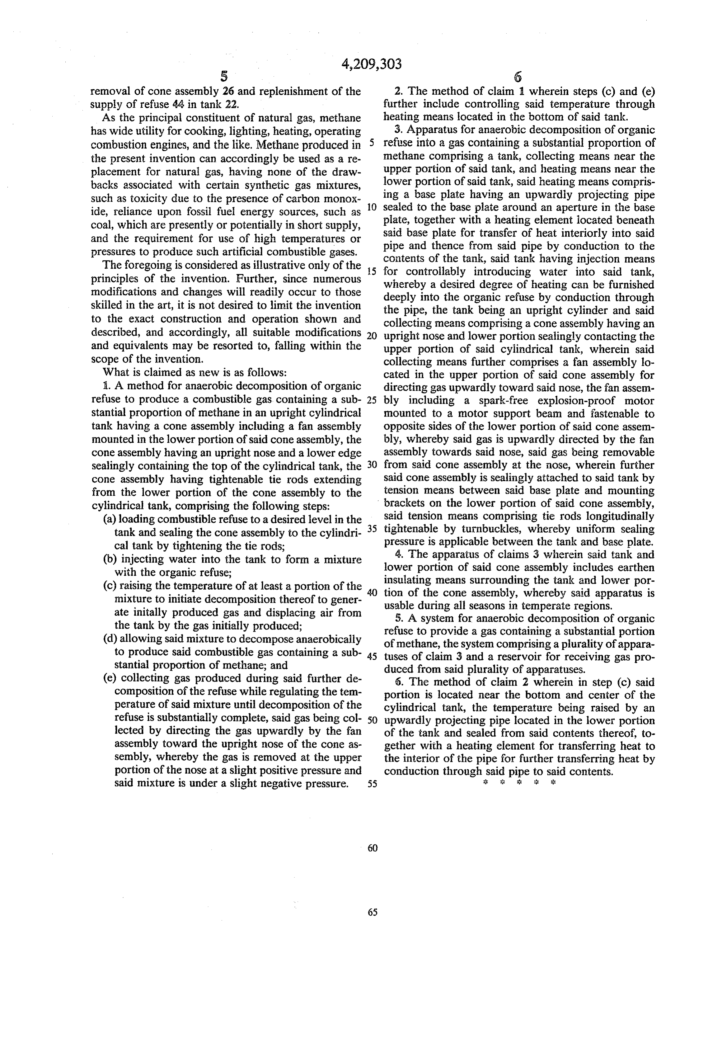
removal of cone assembly 26 and replenishment of the 2. The method of claim a wherein steps (c) and (e) supply of refuse 44 in tank 22. further include controlling said temperature through As the principal constituent of natural gas, methane heating means located in the bottom of said tank. has wide utility for cooking, lighting, heating, operating 3. Apparatus for anaerobic decomposition of organic combustion engines, and the like. Methane produced in refuse into a gas containing a substantial proportion of the present invention can accordingly be used as a re methane comprising a tank, collecting means near the placement for natural gas, having none of the draw upper portion of said tank, and heating means near the backs associated with certain synthetic gas mixtures, ing lower portion of said tank, said heating means compris such as toxicity due to the presence of carbon monox 10 a base plate having an upwardly projecting pipe ide, reliance upon fossil fuel energy sources, such as sealed to the base plate around an aperture in the base plate, together with a heating element located beneath coal, which are presently or potentially in short supply, said and the requirement for use of high temperatures or pipe base and plate for transfer of heat interiorly into said thence from said pipe by conduction to the pressures to produce such artificial combustible gases. contents of the tank, said tank having injection means The foregoing is considered as illustrative only of the 5 for controllably introducing water into said tank, principles of the invention. Further, since numerous whereby a desired degree of heating can be furnished modifications and changes will readily occur to those deeply into the organic refuse by conduction through skilled in the art, it is not desired to limit the invention the pipe, the tank being an upright cylinder and said to the exact construction and operation shown and collecting means comprising a cone assembly having an described, and accordingly, all suitable modifications 20 upright nose and lower portion sealingly contacting the and equivalents may be resorted to, falling within the upper portion of said cylindrical tank, wherein said scope of the invention. collecting means further comprises a fan assembly lo What is claimed as new is as follows: cated in the upper portion of said cone assembly for 1. A method for anaerobic decomposition of organic directing gas upwardly toward said nose, the fan assen refuse to produce a combustible gas containing a sub 25 bly including a spark-free explosion-proof motor stantial proportion of methane in an upright cylindrical mounted to a motor support beam and fastenable to tank having a cone assembly including a fan assembly opposite sides of the lower portion of said cone assem mounted in the lower portion of said cone assembly, the bly, whereby said gas is upwardly directed by the fan cone assembly having an upright nose and a lower edge assembly towards said nose, said gas being removable sealingly containing the top of the cylindrical tank, the 30 from said cone assembly at the nose, wherein further cone assembly having tightenable tie rods extending said cone assembly is sealingly attached to said tank by from the lower portion of the cone assembly to the tension means between said base plate and mounting cylindrical tank, comprising the following steps: brackets on the lower portion of said cone assembly, (a) loading combustible refuse to a desired level in the 35 said tension means comprising tie rods longitudinally tank and sealing the cone assembly to the cylindri tightenable by turnbuckles, whereby uniform sealing cal tank by tightening the tie rods; pressure is applicable between the tank and base plate. (b) injecting water into the tank to form a mixture lower 4. The apparatus of claims 3 wherein said tank and with the organic refuse; portion of said cone assembly includes earthen insulating means surrounding the tank and lower por (c) raising the temperature of at least a portion of the tion mixture to initiate decomposition thereof to gener usableofduring the cone assembly, whereby said apparatus is all seasons in temperate regions.
ate initally produced gas and displacing air from 5. A system for anaerobic decomposition of organic the tank by the gas initially produced; refuse to provide a gas containing a substantial portion (d) allowing said mixture to decompose anaerobically of methane, the system comprising a plurality of appara to produce said combustible gas containing a sub 45 tuses of claim 3 and a reservoir for receiving gas pro stantial proportion of methane; and duced from said plurality of apparatuses. (e) collecting gas produced during said further de 6. The method of claim 2 wherein in step (c) said composition of the refuse while regulating the tem portion is located near the bottom and center of the perature of said mixture until decomposition of the cylindrical tank, the temperature being raised by an refuse is substantially complete, said gas being col 50 upwardly projecting pipe located in the lower portion lected by directing the gas upwardly by the fan of the tank and sealed from said contents thereof, to assembly toward the upright nose of the cone as gether with a heating element for transferring heat to sembly, whereby the gas is removed at the upper the interior of the pipe for further transferring heat by portion of the nose at a slight positive pressure and conduction through said pipe to said contents. said mixture is under a slight negative pressure. 55 & : :
Provenance
- Collection
- Cited prior art
- Original PDF
- patentimages.storage.googleapis.com →
- Filed
- 1978-09-08
- Pages
- 6
- Method
- pdftotext (the PDF's own text layer) + pdftoppm 300dpi page scans
- Source
- Google Patents bibliographic record
- Granted
- 1980-06-24
- Inventors
- Jay W. Ricks
- Transcribed from
- patentimages.storage.googleapis.com →