patent · US4203818
Electrolyzers
20 May 1980
Page 1 — bibliographic record
United States Patent (19) 11) 4,203,818 reaWes
54 ELECTROLYSERS FOREIGN PATENT DOCUMENTS 76 Inventor: Bruce B. Greaves, 3 Fishermans 1278591 6/1972 United Kingdom ............... ... 204/269 Close, Formby, Merseyside, L37 1399898 7/1975 United Kingdom..................... 204/268 1XX, England Primary Examiner-F. C. Edmundson 21 Appl. No.: 37,368 Attorney, Agent, or Firm-Gipple & Hale 22 Filed: May 9, 1979 57 ABSTRACT 30 Foreign Application Priority Data An electrolytic cell comprises an electrolyzing chamber having a pair of terminal electrodes located therein and
May 17, 1978 GB United Kingdom ............... 20020/78 adapted to be connected to the poles of a D.C. source. 51) Int. C.? ........................ C25B 8/00; C25B 15/08; A plurality of bipolar electrodes in the form of parallel C25B 1/34 flat annular discs are located in the chamber between the terminal electrodes and are rotatable about a com 52 U.S.C. .................................... 204/212; 204/268;
204/269 mon central axis through their centers. An electrolyte 58 Field of Search .................. 204/95, 212, 268, 269 inlet is located radially outwardly of the bipolar elec trodes. In order to provide vigorous scouring of the 56 References Cited bipolar electrodes with relative low fluid flows to the
gate slots formed in the cylindrical wall of the chamber 2,839,463 6/1958 Vellas et al. ......................... 204/212 and extending in a direction generally perpendicular to 3,119,759 1/1964 Hoover ................................ 204/212 the planes containing the bipolar disc electrodes. 3,196,095 7/1965 Wadsworth .......................... 204/149 3,649,508 3/1972 Yokota et al. ....................... 204/212 20 Claims, 9 Drawing Figures 3,790,464 2/1974 Greves ................................. 204/212
% litz
Page 2
Drawing sheet — no readable text.
Page 3
Drawing sheet — no readable text.
Page 4
Drawing sheet — no readable text.
Page 5
Drawing sheet — no readable text.
Page 6
Drawing sheet — no readable text.
Page 7
Drawing sheet — no readable text.
Page 8
Drawing sheet — no readable text.
Page 9
have its accepted meaning commonly used in the art,
ELECTROLYSERS namely an intermediate cell electrode without metallic connection with the current supply, one surface of
DESCRIPTION which acts as an anode and the opposite surface as a 5 cathode when an electric current is passed through the
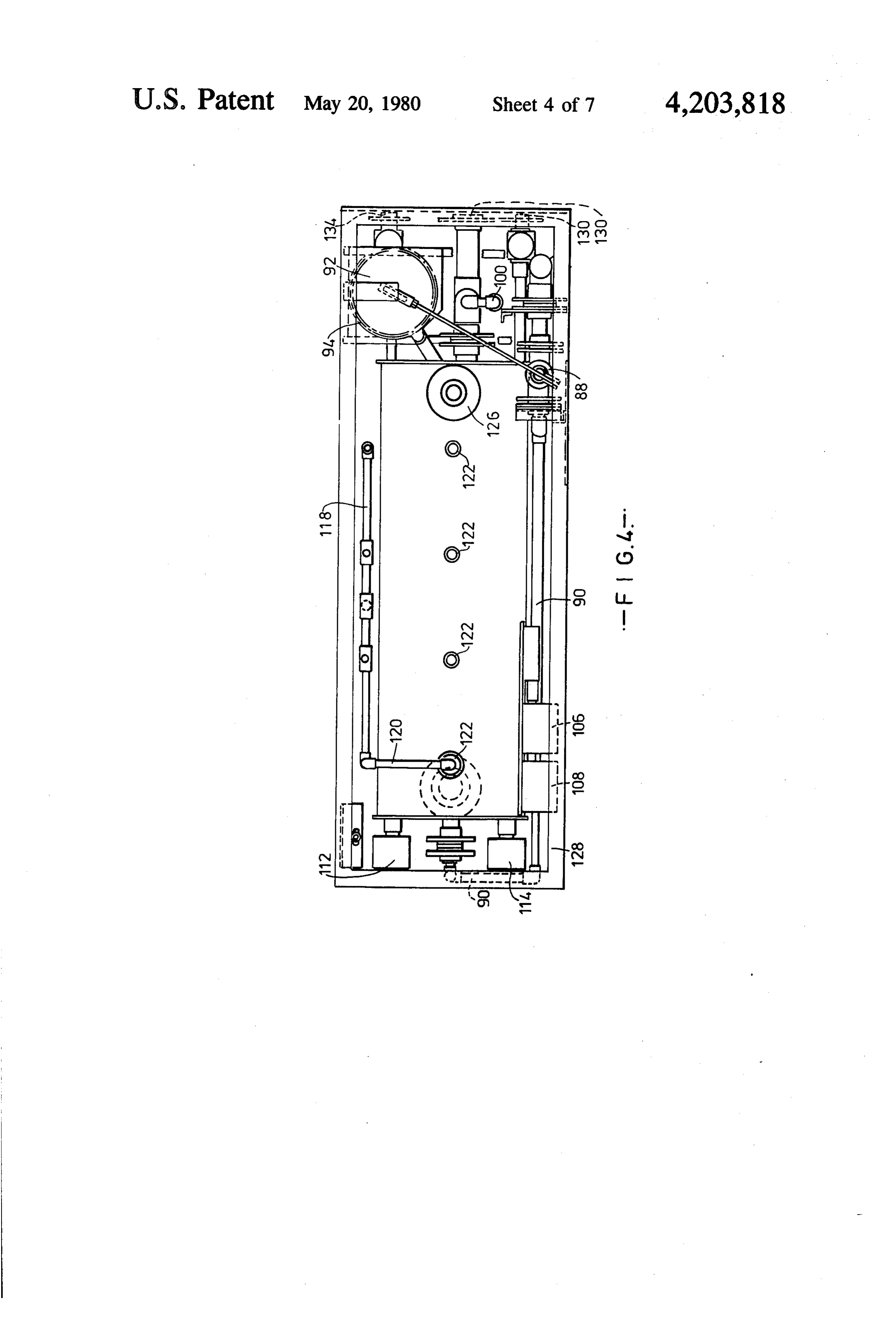
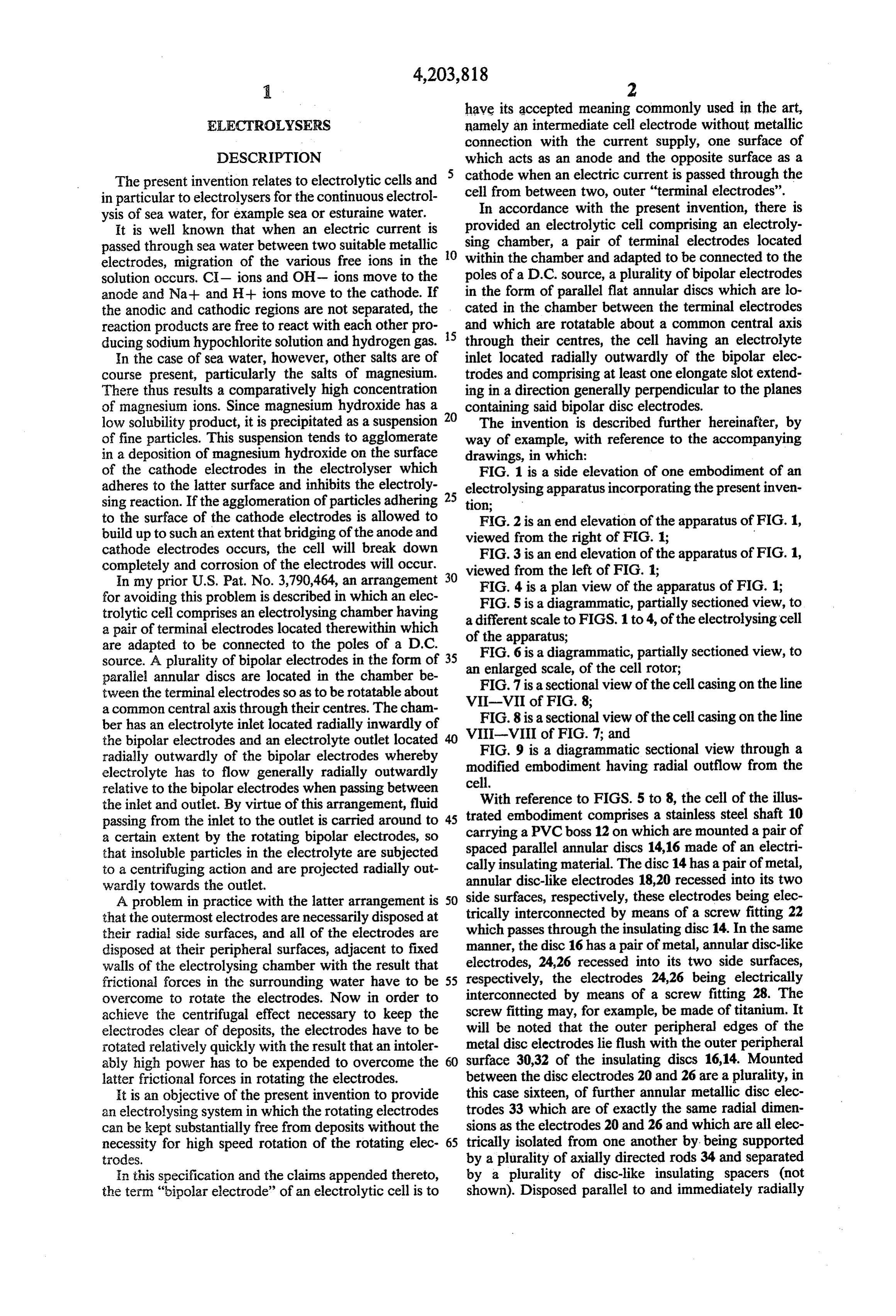
The present invention relates to electrolytic cells and in particular to electrolysers for the continuous electrol cell from between two, outer "terminal electrodes'. ysis of sea water, for example sea or esturaine water. In accordance with the present invention, there is It is well known that when an electric current is provided an electrolytic cell comprising an electroly passed through sea water between two suitable metallic sing chamber, a pair of terminal electrodes located electrodes, migration of the various free ions in the O within the chamber and adapted to be connected to the solution occurs. C- ions and OH- ions move to the poles of a D.C. source, a plurality of bipolar electrodes anode and Na+ and H+ ions move to the cathode. If in the form of parallel flat annular discs which are lo the anodic and cathodic regions are not separated, the cated in the chamber between the terminal electrodes reaction products are free to react with each other pro and which are rotatable about a common central axis ducing sodium hypochlorite solution and hydrogen gas. 5 through their centres, the cell having an electrolyte In the case of sea water, however, other salts are of inlet located radially outwardly of the bipolar elec course present, particularly the salts of magnesium. trodes and comprising at least one elongate slot extend There thus results a comparatively high concentration ing in a direction generally perpendicular to the planes of magnesium ions. Since magnesium hydroxide has a 20 containing said bipolar disc electrodes. low solubility product, it is precipitated as a suspension The invention is described further hereinafter, by of fine particles. This suspension tends to agglomerate way of example, with reference to the accompanying in a deposition of magnesium hydroxide on the surface drawings, in which:
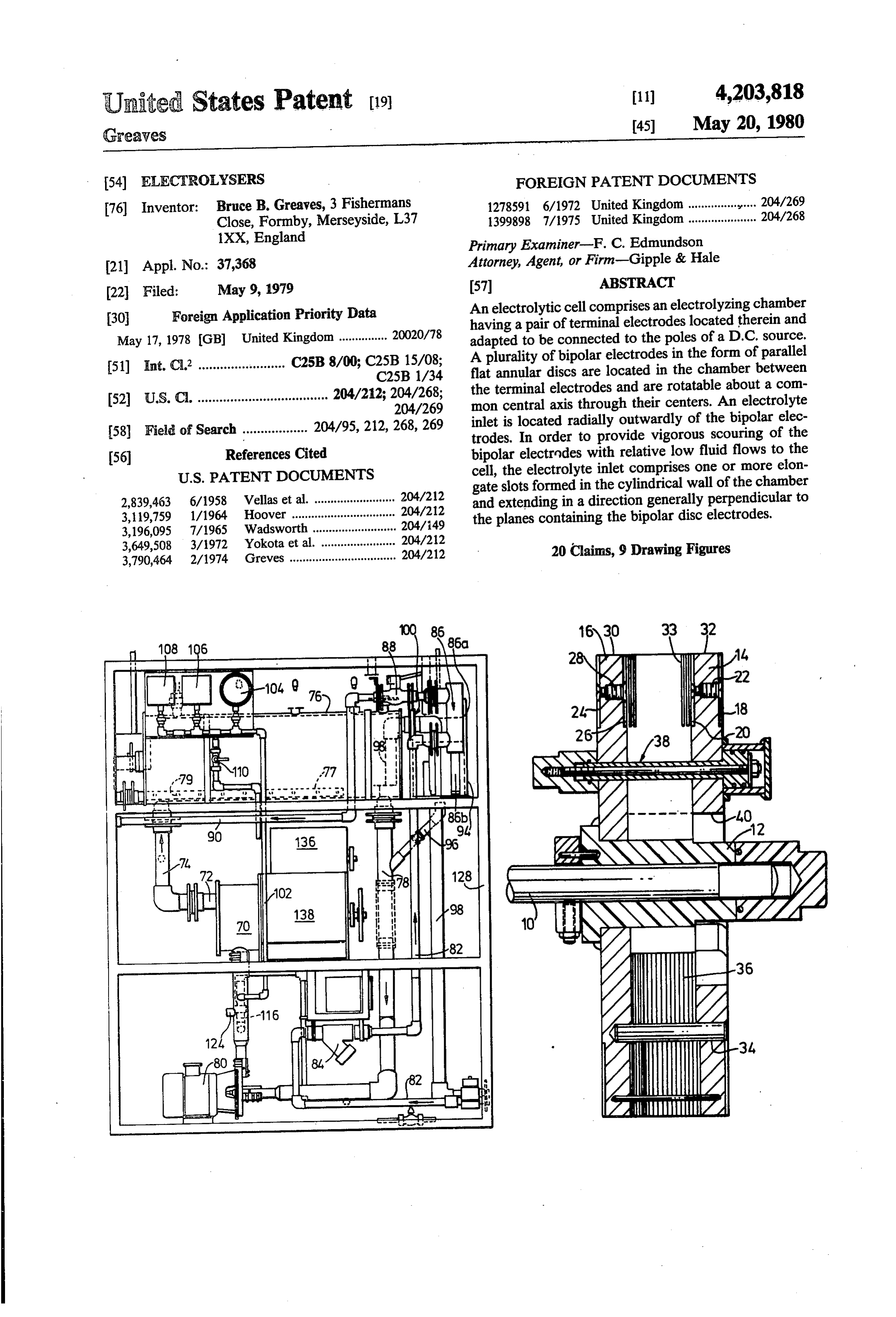
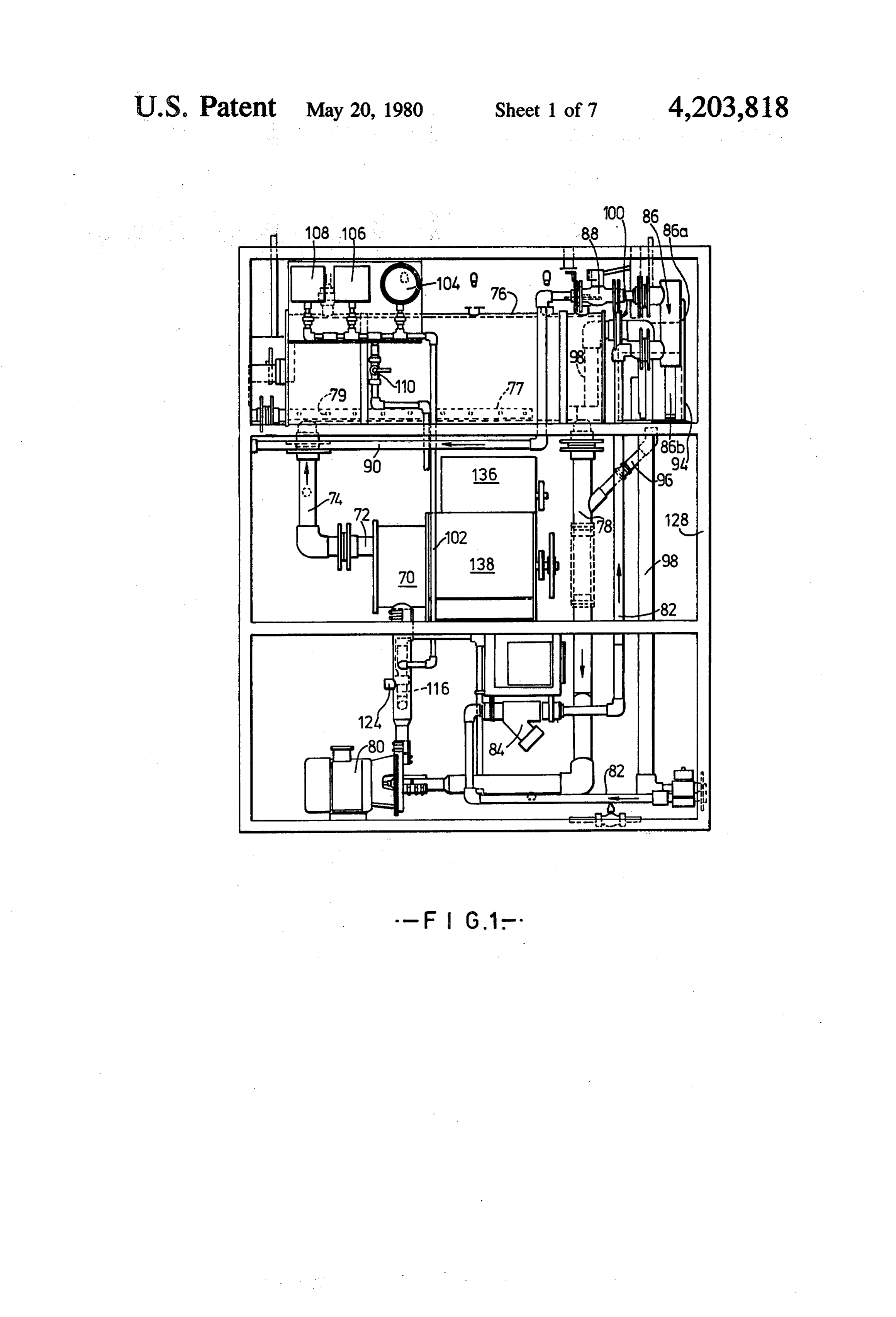
of the cathode electrodes in the electrolyser which FIG. 1 is a side elevation of one embodiment of an adheres to the latter surface and inhibits the electroly electrolysing apparatus incorporating the present inven sing reaction. If the agglomeration of particles adhering tion;
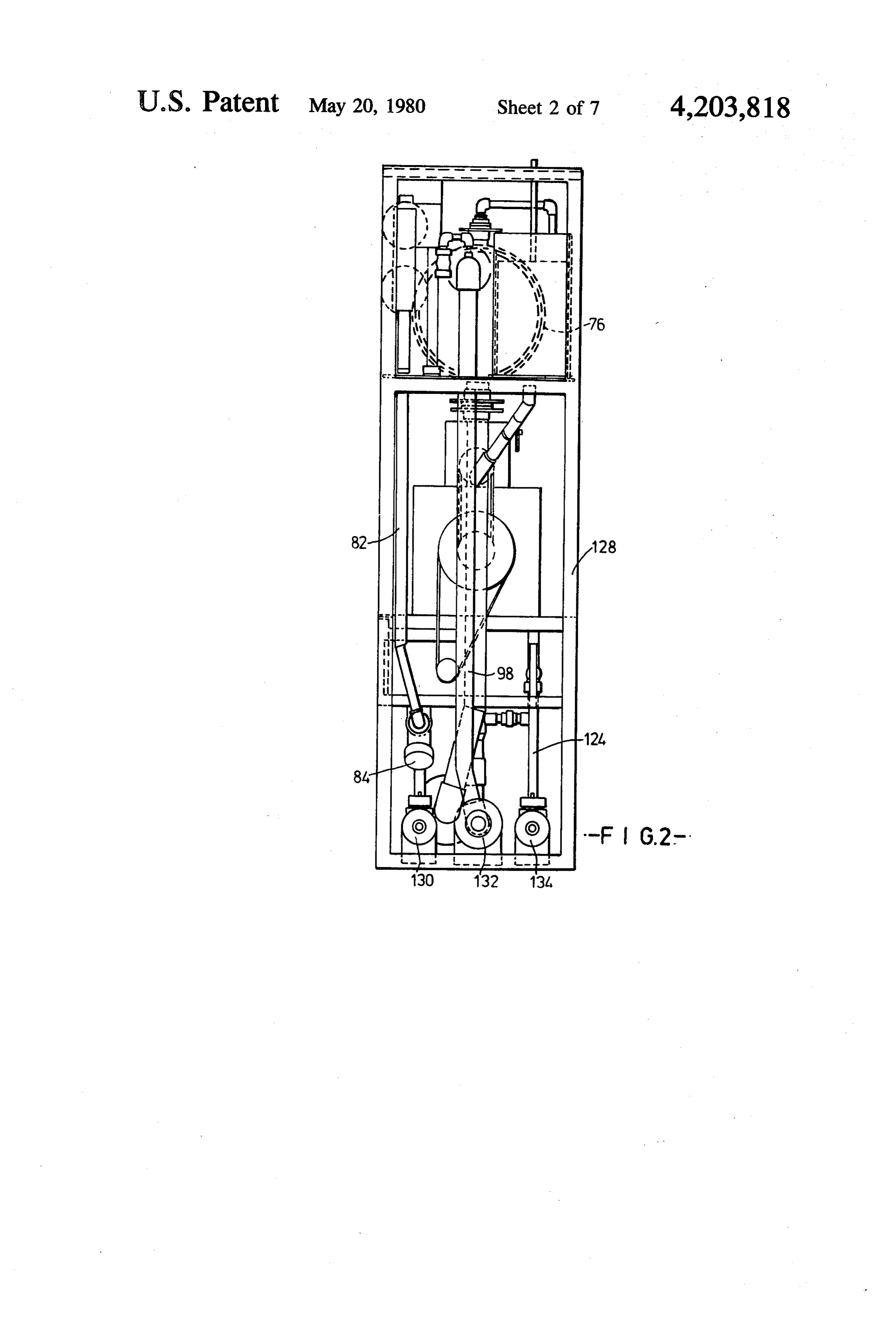
to the surface of the cathode electrodes is allowed to FIG. 2 is an end elevation of the apparatus of FIG. 1, build up to such an extent that bridging of the anode and viewed from the right of FIG. 1;
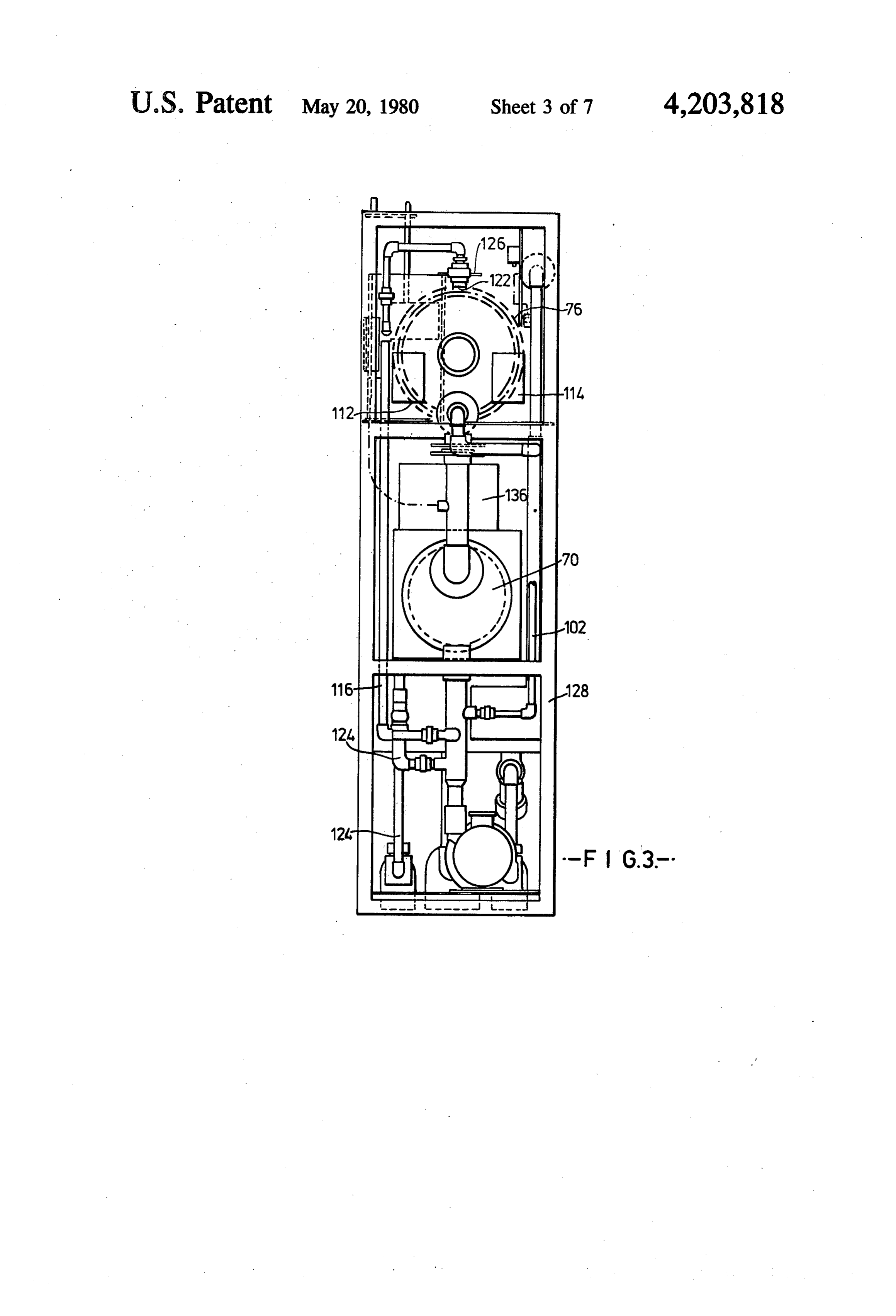
cathode electrodes occurs, the cell will break down FIG. 3 is an end elevation of the apparatus of FIG. 1, completely and corrosion of the electrodes will occur. viewed from the left of FIG. 1;
In my prior U.S. Pat. No. 3,790,464, an arrangement 30 for avoiding this problem is described in which an elec FIG. 4 is a plan view of the apparatus of FIG. 1; FIG.
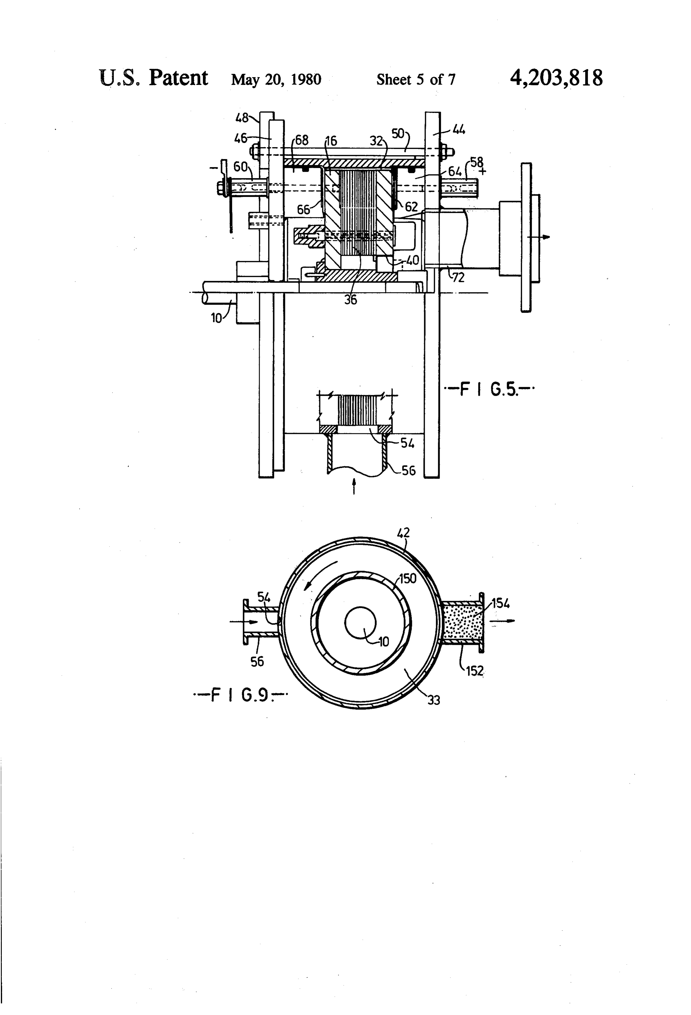
trolytic cell comprises an electrolysing chamber having a different 5 is a diagrammatic, partially sectioned view, to a pair of terminal electrodes located therewithin which of the apparatus; scale to FIGS. 1 to 4, of the electrolysing cell are adapted to be connected to the poles of a D.C.
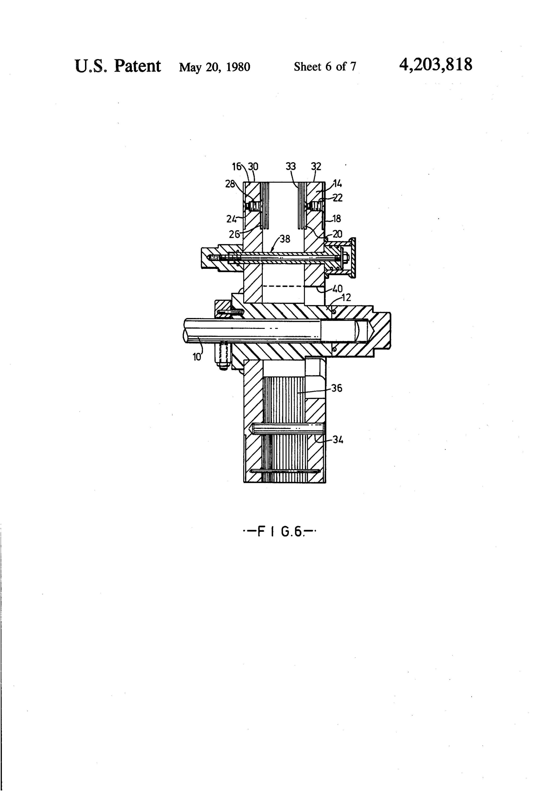
source. A plurality of bipolar electrodes in the form of 35 anFIG. 6 is a diagrammatic, partially sectioned view, to enlarged scale, of the cell rotor;
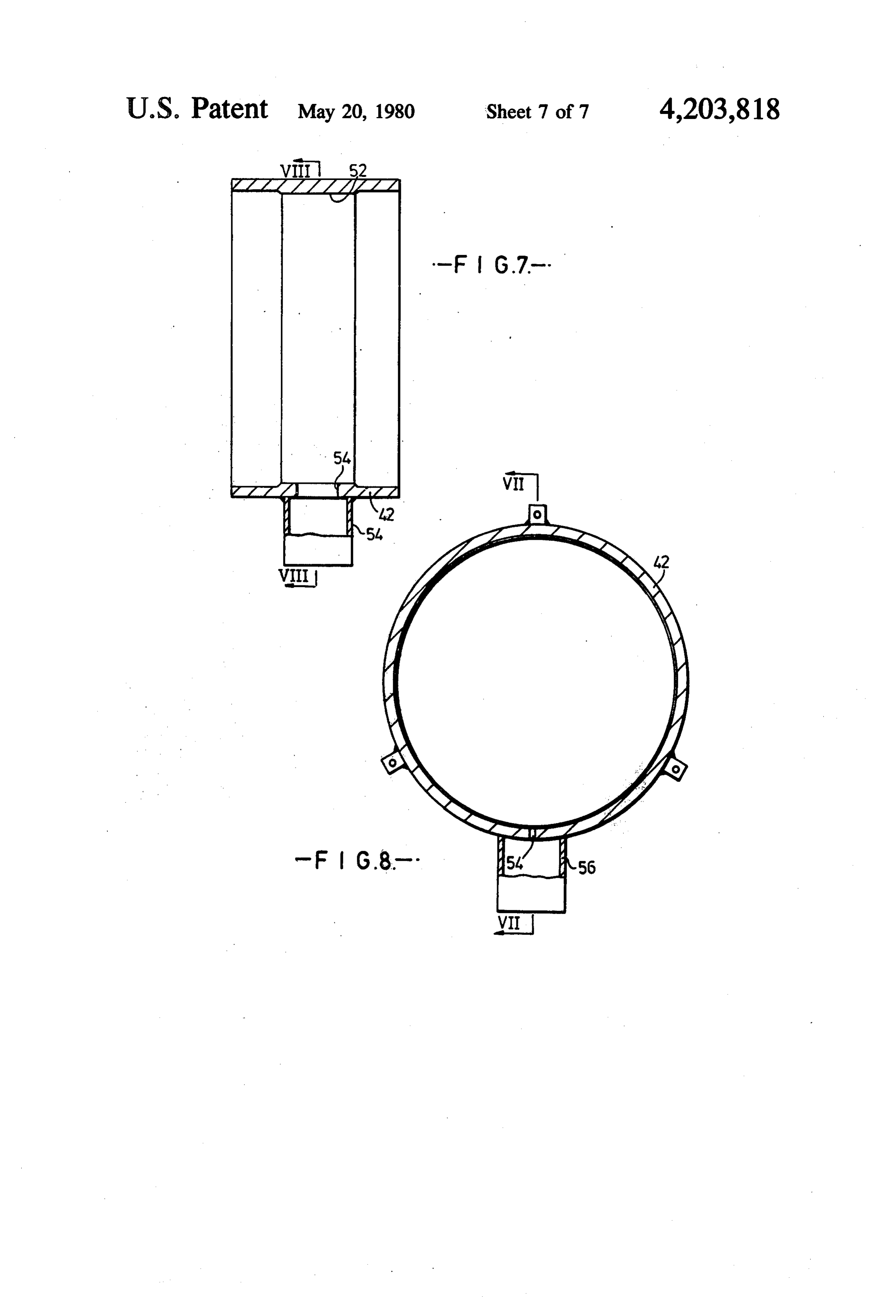
parallel annular discs are located in the chamber be FIG. 7 is a sectional view of the cell casing on the line tween the terminal electrodes so as to be rotatable about a common central axis through their centres. The cham VII-VII of FIG. 8;
FIG. 8 is a sectional view of the cell casing on the line ber has an electrolyte inlet located radially inwardly of the bipolar electrodes and an electrolyte outlet located 40 VIII-VIII of FIG. 7; and FIG. 9 is a diagrammatic sectional view through a radially outwardly of the bipolar electrodes whereby electrolyte has to flow generally radially outwardly modified embodiment having radial outflow from the relative to the bipolar electrodes when passing between cell.With reference to FIGS. 5 to 8, the cell of the illus the inlet and outlet. By virtue of this arrangement, fluid passing from the inlet to the outlet is carried around to 45 trated embodiment comprises a stainless steel shaft 10 a certain extent by the rotating bipolar electrodes, so spacedcarrying a PVC boss 12 on which are mounted a pair of that insoluble particles in the electrolyte are subjected parallel annular discs 14,16 made of an electri to a centrifuging action and are projected radially out cally insulating material. The disc 14 has a pair of metal, wardly towards the outlet. annular disc-like electrodes 18,20 recessed into its two A problem in practice with the latter arrangement is 50 side surfaces, respectively, these electrodes being elec that the outermost electrodes are necessarily disposed at trically which interconnected by means of a screw fitting 22 passes through the insulating disc 14. In the same their radial side surfaces, and all of the electrodes are disposed at their peripheral surfaces, adjacent to fixed manner, the disc 16 has a pair of metal, annular disc-like walls of the electrolysing chamber with the result that electrodes, 24,26 recessed into its two side surfaces, frictional forces in the surrounding water have to be 55 respectively, the electrodes 24.26 being electrically overcome to rotate the electrodes. Now in order to interconnected by means of a screw fitting 28. The achieve the centrifugal effect necessary to keep the screw fitting may, for example, be made of titanium. It electrodes clear of deposits, the electrodes have to be will be noted that the outer peripheral edges of the rotated relatively quickly with the result that an intoler metal disc electrodes lie flush with the outer peripheral ably high power has to be expended to overcome the 60 surface 30,32 of the insulating discs 16,14. Mounted latter frictional forces in rotating the electrodes. between the disc electrodes 20 and 26 are a plurality, in it is an objective of the present invention to provide this case sixteen, of further annular metallic disc elec an electrolysing system in which the rotating electrodes trodes 33 which are of exactly the same radial dimen can be kept substantially free from deposits without the sions as the electrodes 20 and 26 and which are all elec necessity for high speed rotation of the rotating elec 65 trically isolated from one another by, being supported trodes. by a plurality of axially directed rods 34 and separated in this specification and the claims appended thereto, by a plurality of disc-like insulating spacers (not the term "bipolar electrode' of an electrolytic cell is to shown). Disposed parallel to and immediately radially
Page 10
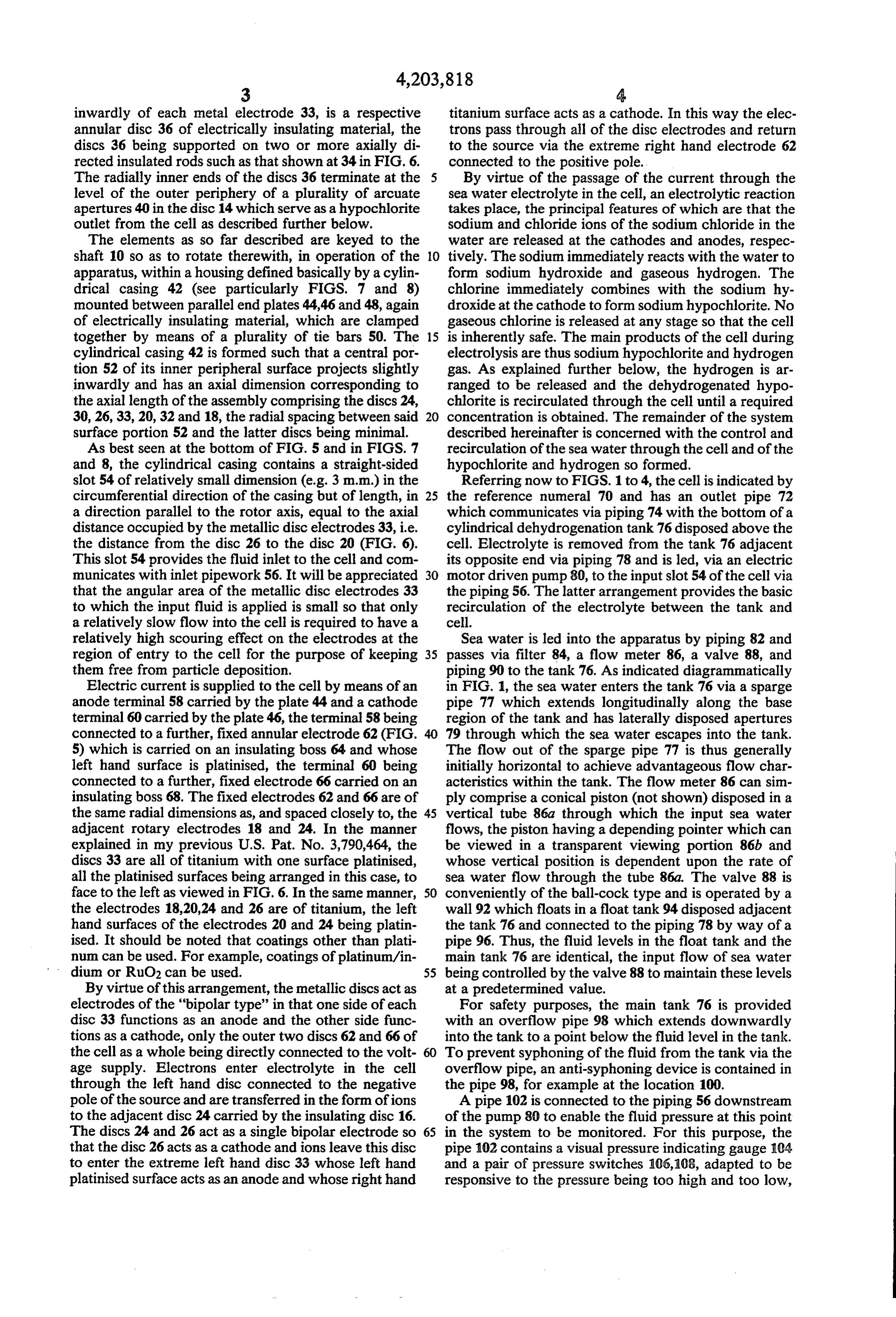
inwardly of each metal electrode 33, is a respective titanium surface acts as a cathode. In this way the elec annular disc 36 of electrically insulating material, the trons pass through all of the disc electrodes and return discs 36 being supported on two or more axially di to the source via the extreme right hand electrode 62 rected insulated rods such as that shown at 34 in FIG. 6. connected to the positive pole. The radially inner ends of the discs 36 terminate at the By virtue of the passage of the current through the level of the outer periphery of a plurality of arcuate sea water electrolyte in the cell, an electrolytic reaction apertures 40 in the disc 14 which serve as a hypochlorite takes place, the principal features of which are that the outlet from the cell as described further below. sodium and chloride ions of the sodium chloride in the The elements as so far described are keyed to the water are released at the cathodes and anodes, respec shaft 10 so as to rotate therewith, in operation of the 10 tively. The sodium immediately reacts with the water to apparatus, within a housing defined basically by a cylin form sodium hydroxide and gaseous hydrogen. The drical casing 42 (see particularly FIGS. 7 and 8) chlorine immediately combines with the sodium hy mounted between parallel end plates 44,46 and 48, again droxide at the cathode to form sodium hypochlorite. No of electrically insulating material, which are clamped gaseous chlorine is released at any stage so that the cell together by means of a plurality of tie bars 50. The 15 is inherently safe. The main products of the cell during cylindrical casing 42 is formed such that a central por electrolysis are thus sodium hypochlorite and hydrogen tion 52 of its inner peripheral surface projects slightly gas. As explained further below, the hydrogen is ar inwardly and has an axial dimension corresponding to ranged to be released and the dehydrogenated hypo the axial length of the assembly comprising the discs 24, chlorite is recirculated through the cell until a required 30, 26, 33, 20, 32 and 18, the radial spacing between said concentration is obtained. The remainder of the system surface portion 52 and the latter discs being minimal. described hereinafter is concerned with the control and As best seen at the bottom of FIG. 5 and in FIGS. 7 recirculation of the sea water through the cell and of the and 8, the cylindrical casing contains a straight-sided hypochlorite and hydrogen so formed. slot 54 of relatively small dimension (e.g. 3 m.m.) in the Referring now to FIGS. 1 to 4, the cell is indicated by circumferential direction of the casing but of length, in 25 the reference numeral 70 and has an outlet pipe 72 a direction parallel to the rotor axis, equal to the axial which communicates via piping 74 with the bottom of a distance occupied by the metallic disc electrodes 33, i.e. cylindrical dehydrogenation tank 76 disposed above the the distance from the disc 26 to the disc 20 (FIG. 6). cell. Electrolyte is removed from the tank 76 adjacent This slot 54 provides the fluid inlet to the cell and com its opposite end via piping 78 and is led, via an electric municates with inlet pipework 56. It will be appreciated 30 motor driven pump 80, to the input slot 54 of the cell via that the angular area of the metallic disc electrodes 33 the piping 56. The latter arrangement provides the basic to which the input fluid is applied is small so that only recirculation of the electrolyte between the tank and a relatively slow flow into the cell is required to have a cell.
relatively high scouring effect on the electrodes at the Sea water is led into the apparatus by piping 82 and region of entry to the cell for the purpose of keeping 35 passes via filter 84, a flow meter 86, a valve 88, and them free from particle deposition. piping 90 to the tank 76. As indicated diagrammatically Electric current is supplied to the cell by means of an in FIG. 1, the sea water enters the tank 76 via a sparge anode terminal 58 carried by the plate 44 and a cathode pipe 77 which extends longitudinally along the base terminal 60 carried by the plate 46, the terminal 58 being region of the tank and has laterally disposed apertures connected to a further, fixed annular electrode 62 (FIG. 79 through which the sea water escapes into the tank. 5) which is carried on an insulating boss 64 and whose The flow out of the sparge pipe 77 is thus generally left hand surface is platinised, the terminal 60 being initially horizontal to achieve advantageous flow char connected to a further, fixed electrode 66 carried on an acteristics within the tank. The flow meter 86 can sim insulating boss 68. The fixed electrodes 62 and 66 are of ply comprise a conical piston (not shown) disposed in a the same radial dimensions as, and spaced closely to, the 45 vertical tube 86a through which the input sea water adjacent rotary electrodes 18 and 24. In the manner flows, the piston having a depending pointer which can explained in my previous U.S. Pat. No. 3,790,464, the be viewed in a transparent viewing portion 86b and discs 33 are all of titanium with one surface platinised, whose vertical position is dependent upon the rate of all the platinised surfaces being arranged in this case, to sea water flow through the tube 86a. The valve 88 is face to the left as viewed in FIG. 6. In the same manner, 50 conveniently of the ball-cock type and is operated by a the electrodes 18,20,24 and 26 are of titanium, the left wall 92 which floats in a float tank 94 disposed adjacent hand surfaces of the electrodes 20 and 24 being platin the tank 76 and connected to the piping 78 by way of a ised. It should be noted that coatings other than plati pipe 96. Thus, the fluid levels in the float tank and the num can be used. For example, coatings of platinum/in main tank 76 are identical, the input flow of sea water dium or RuO2 can be used. 55 being controlled by the valve 88 to maintain these levels By virtue of this arrangement, the metallic discs act as at a predetermined value.
electrodes of the "bipolar type' in that one side of each For safety purposes, the main tank 76 is provided disc 33 functions as an anode and the other side func with an overflow pipe 98 which extends downwardly tions as a cathode, only the outer two discs 62 and 66 of into the tank to a point below the fluid level in the tank. the cell as a whole being directly connected to the volt 60 To prevent syphoning of the fluid from the tank via the age supply. Electrons enter electrolyte in the cell overflow pipe, an anti-syphoning device is contained in through the left hand disc connected to the negative the pipe 98, for example at the location 100. pole of the source and are transferred in the form of ions A pipe 102 is connected to the piping 56 downstream to the adjacent disc 24 carried by the insulating disc 16. of the pump 80 to enable the fluid pressure at this point The discs 24 and 26 act as a single bipolar electrode so 65 in the system to be monitored. For this purpose, the that the disc 26 acts as a cathode and ions leave this disc pipe 102 contains a visual pressure indicating gauge 104 to enter the extreme left hand disc 33 whose left hand and a pair of pressure switches 106,108, adapted to be platinised surface acts as an anode and whose right hand responsive to the pressure being too high and too low,
Page 11
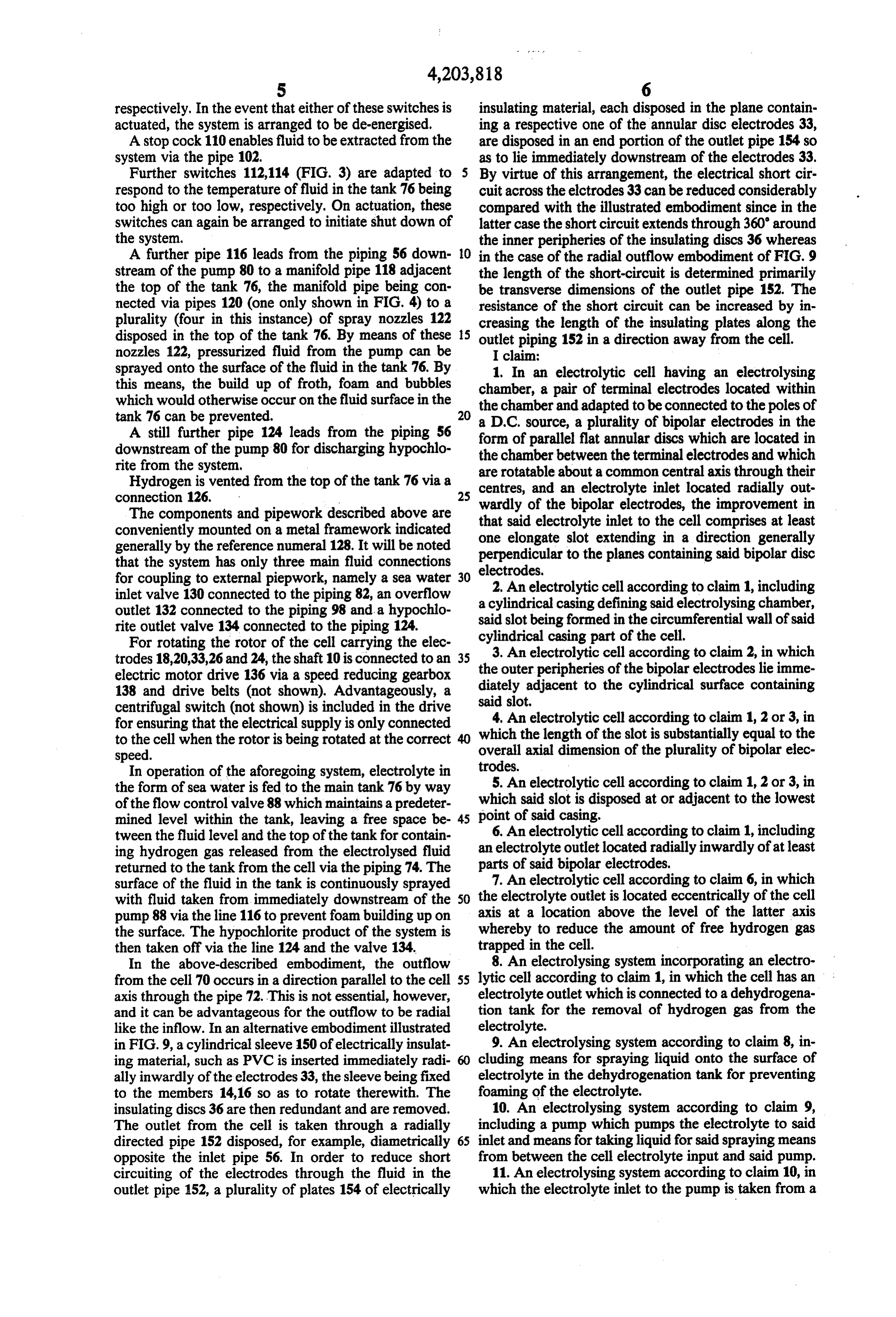
respectively. In the event that either of these switches is insulating material, each disposed in the plane contain actuated, the system is arranged to be de-energised. ing a respective one of the annular disc electrodes 33, A stop cock 110 enables fluid to be extracted from the are disposed in an end portion of the outlet pipe 154 so system via the pipe 102. as to lie immediately downstream of the electrodes 33. Further switches 112,114 (FIG. 3) are adapted to 5 By virtue of this arrangement, the electrical short cir respond to the temperature of fluid in the tank 76 being cuit across the elctrodes 33 can be reduced considerably too high or too low, respectively. On actuation, these compared with the illustrated embodiment since in the switches can again be arranged to initiate shut down of latter case the short circuit extends through 360 around the system. the inner peripheries of the insulating discs 36 whereas A further pipe 116 leads from the piping 56 down O in the case of the radial outflow embodiment of FIG. 9 stream of the pump 80 to a manifold pipe 118 adjacent the length of the short-circuit is determined primarily the top of the tank 76, the manifold pipe being con be transverse dimensions of the outlet pipe 152. The nected via pipes 120 (one only shown in FIG. 4) to a resistance of the short circuit can be increased by in plurality (four in this instance) of spray nozzles 122 creasing the length of the insulating plates along the disposed in the top of the tank 76. By means of these 15 outlet piping 152 in a direction away from the cell. nozzles 122, pressurized fluid from the pump can be I claim:
sprayed onto the surface of the fluid in the tank 76. By 1. In an electrolytic cell having an electrolysing this means, the build up of froth, foam and bubbles chamber, a pair of terminal electrodes located within which would otherwise occur on the fluid surface in the the chamber and adapted to be connected to the poles of tank 76 can be prevented. 20
A still further pipe 124 leads from the piping 56 form ofsource,
parallel a plurality of bipolar electrodes in the flat annular discs which are located in downstream of the pump 80 for discharging hypochlo the chamber between the terminal electrodes and which rite from the system. are rotatable about a common central axis through their Hydrogen is vented from the top of the tank 76 via a centres, and an electrolyte inlet located radially out connection 126.
The components and pipework described above are that said electrolyte inlet to the cellthecomprises wardly of the bipolar electrodes, improvement in at least conveniently mounted on a metal framework indicated one elongate slot extending in a direction generally generally by the reference numeral 128. It will be noted perpendicular to the planes containing said bipolar disc that the system has only three main fluid connections electrodes, for coupling to external piepwork, namely a sea water 30 2. An electrolytic cell according to claim 1, including inlet valve 130 connected to the piping 82, an overflow a cylindrical casing defining said electrolysing chamber, outlet 132 connected to the piping 98 and a hypochlo said slot being formed in the circumferential wall of said rite outlet valve 134 connected to the piping 124.
For rotating the rotor of the cell carrying the elec cylindrical casing part of the cell. trodes 18,20,33,26 and 24, the shaft 10 is connected to an 35 the outer peripheriescell 3. An electrolytic according to claim 2, in which of the bipolar electrodes lie imme electric motor drive 136 via a speed reducing gearbox diately 138 and drive belts (not shown). Advantageously, a said slot.adjacent to the cylindrical surface containing centrifugal switch (not shown) is included in the drive 4. An electrolytic cell according to claim 1, 2 or 3, in for ensuring that the electrical supply is only connected which to the cell when the rotor is being rotated at the correct 40 overallthe length of the slot is substantially equal to the axial dimension of the plurality of bipolar elec speed.
In operation of the aforegoing system, electrolyte in trodes.
the form of sea water is fed to the main tank 76 by way 5. An electrolytic cell according to claim 1, 2 or 3, in of the flow control valve 88 which maintains a predeter point which said slot is disposed at or adjacent to the lowest mined level within the tank, leaving a free space be 45 6. An of said casing.
tween the fluid level and the top of the tank for contain an electrolyte electrolytic cell according to claim 1, including ing hydrogen gas released from the electrolysed fluid outlet located radially inwardly of at least returned to the tank from the cell via the piping 74. The parts of said bipolar electrodes, surface of the fluid in the tank is continuously sprayed 7. An electrolytic cell according to claim 6, in which with fluid taken from immediately downstream of the 50 the electrolyte outlet is located eccentrically of the cell pump 88 via the line 116 to prevent foam building up on axis at a location above the level of the latter axis the surface. The hypochlorite product of the system is whereby to reduce the amount of free hydrogen gas then taken off via the line 124 and the valve 134. trapped in the cell.
In the above-described embodiment, the outflow 8. An electrolysing system incorporating an electro from the cell 70 occurs in a direction parallel to the cell 55 lytic cell according to claim 1, in which the cell has an axis through the pipe 72. This is not essential, however, electrolyte outlet which is connected to a dehydrogena and it can be advantageous for the outflow to be radial tion tank for the removal of hydrogen gas from the like the inflow. In an alternative embodiment illustrated electrolyte.
in FIG.9, a cylindrical sleeve 150 of electrically insulat 9. An electrolysing system according to claim 8, in ing material, such as PVC is inserted immediately radi cluding means for spraying liquid onto the surface of ally inwardly of the electrodes 33, the sleeve being fixed electrolyte in the dehydrogenation tank for preventing to the members 14,16 so as to rotate therewith. The foaming of the electrolyte.
insulating discs 36 are then redundant and are removed. 10. An electrolysing system according to claim 9, The outlet from the cell is taken through a radially including a pump which pumps the electrolyte to said directed pipe 152 disposed, for example, diametrically 65 inlet and means for taking liquid for said spraying means opposite the inlet pipe 56. In order to reduce short from between the cell electrolyte input and said pump. circuiting of the electrodes through the fluid in the 11. An electrolysing system according to claim 10, in outlet pipe 152, a plurality of plates 154 of electrically which the electrolyte inlet to the pump is taken from a
Page 12
region of the dehydrogenation tank remote from the the tank and via which raw input electrolyte is supplied region of entry of electrolyte from the cell. to the dehydrogenation tank, the sparge pipe having a 12. An electrolysing system according to claim 9, 10 plurality of generally horizontally directed outlet aper or 11, including a sparge pipe disposed adjacent the base tures.
of the tank and via which raw input electrolyte is sup- 5 19. An electrolytic cell comprising a casing which plied to the dehydrogenation tank, the sparge pipe hav has a cylindrical inner surface and which defines an ing a plurality of generally horizontally directed outlet electrolysing chamber, a pair of terminal electrodes apertures. located within the chamber and adapted to be con 13. An electrolytic cell comprising a casing which nected to the poles of a D.C. source, a plurality of bipo has a cylindrical inner surface and which defines an 10 lar electrodes in the form of parallel flat annular discs electrolysing chamber, a pair of terminal electrodes which are located in the chamber between the terminal located within the chamber and adapted to be con electrodes and which are rotatable about a common nected to the poles of a D.C. source, a plurality of bipo central axis through their centres, the outer peripheries lar electrodes in the form of parallel flat annular discs of the bipolar electrodes lying immediately adjacent to which are located in the chamber between the terminal 15 the cylindrical inner surface of said casing, the cell electrodes and which are rotatable about a common having an electrolyte inlet located radially outwardly of central aixs through their centres, the outer peripheries the bipolar electrodes and comprising at least one elon of the bipolar electrodes lying immediately adjacent to gate slot disposed in said cylindrical wall surface of the the cylindrical inner surface of said casing, the cell casing and extending in a direction generally perpendic having an electrolyte inlet located radially outwardly of 20 ular to the planes containing said bipolar disc elec the bipolar electrodes and comprising at least one elon trodes, the length of said slot being substantially equal gate slot disposed in said cylindrical wall surface of the to the overall axial dimension of said plurality of bipolar casing extending in a direction generally perpendicular electrodes and the cell having an electrolyte outlet to the planes containing said bipolar disc electrodes, the located radially outwardly of the bipolar electrodes and length of said slot being substantially equal to the over 25 comprising at least one generally radially extending all axial dimension of said plurality of bipolar elec outlet pipe communicating with an aperture in the cy trodes. lindrical wall surface of the casing, said outlet pipe 14. An electrolytic cell according to claim 13, in containing a plurality of sheets of electrically insulating which said slot is disposed at or adjacent to the lowest material disposed immediately downstream of the bipo point of said casing. 30 lar electrodes in planes parallel to respective ones of 15. An electrolysing system including an electrolytic said bipolar electrodes.
cell comprising a casing which has a cylindrical inner 20. An electrolysing system including an electrolytic surface and which defines an electrolysing chamber, a cell comprising a casing which has a cylindrical inner pair of terminal electrodes located within the chamber surface and which defines an electrolysing chamber, a and adapted to be connected to the poles of a D.C. 35 pair of terminal electrodes located within the chamber source, a plurality of bipolar electrodes in the form of and adapted to be connected to the poles of a D.C. parallel flat annular discs which are located in the source, a plurality of bipolar electrodes in the form of chamber between the terminal electrodes and which are parallel flat annular discs which are located in the rotatable about a common central axis through their chamber between the terminal electrodes and which are centres, the outer peripheries of the bipolar electrodes 40 rotatable about a common central axis through their lying immediately adjacent to the cylindrical inner sur centres, the outer peripheries of the bipolar electrodes face of said casing, the cell having an electrolyte inlet lying immediately adjacent to the cylindrical inner sur located radially outwardly of the bipolar electrodes and face of said casing, the cell having an electrolyte inlet comprising at least one elongate slot disposed in said located radially outwardly of the bipolar electrodes and cylindrical wall surface of the casing and extending in a 45 comprising at least one elongate slot disposed in said direction generally perpendicular to the planes contain cylindrical wall surface of the casing and extending in a ing said bipolar disc electrodes, the length of said slot direction generally perpendicular to the planes contain being substantially equal to the overall axial dimension ing said bipolar disc electrodes, the length of said slot of said plurality of bipolar electrodes, an electrolyte being substantially equal to the overall axial dimension outlet, a dehydrogenation tank for the removal of hy 50 of said plurality of bipolar electrodes, an electrolyte drogen gas from the electrolyte, means connecting the outlet, a dehydrogenation tank for the removal of hy electrolyte outlet to the dehydrogenation tank, and drogen gas from the electrolyte, means connecting the means for spraying liquid onto the surface of electrolyte electrolyte outlet to the dehydrogenation tank, and in the dehydrogenation tank for preventing foaming of means for spraying liquid onto the surface of electrolyte the electrolyte. 55 in the dehydrogenation tank for preventing foaming of 16. An electrolysing system according to claim 15, the electrolyte, the electrolyte outlet being located radi including a pump which pumps the electrolyte to said ally outwardly of the bipolar electrodes and comprising inlet, and means for taking liquid for said spraying at least one generally radially extending outlet pipe means from between the cell electrolyte input and said communicating with an aperture in the cylindrical wall pump. 60 surface of the casing, said outlet pipe containing a plu 17. An electrolysing system according to claim 16, in rality of sheets of electrically insulating material dis which the electrolyte inlet to the pump is taken from a posed immediately downstream of the bipolar elec region of entry of electrolyte from the cell. trodes in planes parallel to respective ones of said bipo 18. An electrolysing system according to claim 17, lar electrodes.
including a sparge pipe disposed adjacent to the base of 65 a:
Provenance
- Collection
- Cited prior art
- Original PDF
- patentimages.storage.googleapis.com →
- Filed
- 1979-05-09
- Pages
- 12
- Method
- pdftotext (the PDF's own text layer) + pdftoppm 300dpi page scans
- Source
- Google Patents bibliographic record
- Granted
- 1980-05-20
- Inventors
- Bruce B. Greaves
- Transcribed from
- patentimages.storage.googleapis.com →