patent · US4140090
Precombustion chamber, stratified charge internal combustion engine system using a highly combustible gas in the precombustion chamber
20 February 1979
Page 1 — bibliographic record
United States Patent (19) 11 4,140,090 Lindberg (45) Feb. 20, 1979 (54 PRECOMBUSTION CHAMBER, 57 ABSTRACT
STRATFED CHARGE INTERNAL
COMBUSTION ENGINE SYSTEM USINGA A gaseous fuel is used in a precombustion chamber for HGHLY COMBUSTIBLE GAS IN THE igniting lean fuel-oxidant mixtures in a main combustion PRECOMBUSTION CHAMBER chamber of an internal combustion engine. The precombustion chamber preferably utilizes a highly 75 Inventor: John E. Lindberg, Berkeley, Calif. combustible gaseous fuel which burns clean with little 73) Assignee: Owen, Wickersham & Erickson, San or no deposits and produces no pollutants. Francisco, Calif. The combustion gas products from the precombustion 21 Appl. No.: 623,482 chamber are injected into the main combustion chamber at high temperature and at high velocity to produce 22 Filed: Oct. 17, 1975 highly efficient turbulent mixing of a lean fuel-oxidant 51 Int. C.?........................ FO2B 75/02; FO2B33/00 mixture in the main combustion chamber and to pro 52 U.S. C. ................................. 123/75 B; 123/1 A; duce effective ignition and efficient burning of the fuel 123/3; 123/32 ST; 123/119 EE; 123/191 SP; at the lean fuel-oxidant ratios in the main combustion 123/DIG. 12 chamber for increased engine efficiency and lowered 58. Field of Search ............ 123/1 A, 3, 32 K, 32 SP, emissions as compared to existing engine systems using 123/32 ST, 75 B, 19 E, 121, 127, 191 S, 191 conventional spark ignition.
SP, DIG. 12, 119 EE; 204/230, 129 The precombustion chamber mechanism incorporates (56) References Cited injection structure for producing standing waves in the main combustion chamber to provide a plurality of
1,181,122 5/1916 Eastman ........................... 123/32 SP In preferred forms of the present invention hydrogen is 1,380,183 5/1921 Boisen .................................. 204/230 utilized as the gaseous fuel for the precombustion cham 1,422,794 7/1922 Smith ............................... 123/32 SP ber to provide absolutely clean combustion. 1,957,541 5/1934 Johnson ........................... 23/32 SP An electrolytic generator can be incorporated with the 2,238,852 4/1941 Regar .. ... 123/191 SP 2,384,463 11/1945 Gunn. 123ADIG. 12 precombustion chamber mechanism for generating hy 2,617,841 1/1952 Linder .............................. 123/148 E drogen and oxygen gases to operate the precombustion 3,406,667 10/1968 Evans et al. ..................... 123/32 SP chamber. The electrolytic generator includes an auto 3,433,729 3/1969 Proskuryahov et al. ............ 204/129 matic water feed system for replacing the water used to 3,784,096 l/1974 Zweifel ................................ 204/230 generate the hydrogen and oxygen gases and incorpo 3,939,806 2/1976 Bradley ........... . 123/DIG. 12 rates an electrode and internal pressurization arrange 3,955,538 5/1976 Noguchi et al. ......................... 123/3 ment for automatically shutting off the generation of 3,970,054 7/1976 Henault et al. .................. 123/32. ST hydrogen and oxygen gases on engine shut-down and Primary Examiner-Ronald H. Lazarus for storing a sufficient quantity of hydrogen and oxygen Assistant Examiner-David D. Reynolds gases to facilitate subsequent engine start-up. Attorney, Agent, or Firm-Owen, Wickersham &
Erickson 23 Claims, 5 Drawing Figures
HGHLY
FLAMMABLE
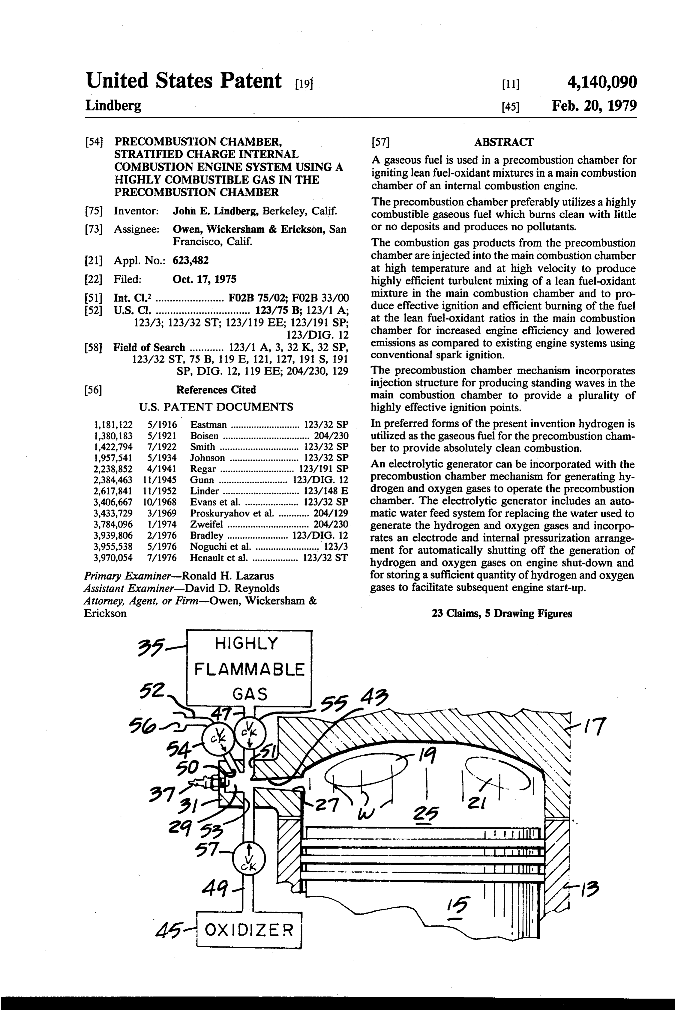
Page 2
Drawing sheet — no readable text.
Page 3
relatively complex and bulky poppet valve arrangement
PRECOMBUSTION CHAMBER, STRATIFIED
CHARGE INTERNAL COMBUSTION ENGINE
. which must be timed in coordination with other engine . . structure to control the inlet of the mixture into the
SYSTEM USINGA HIGHILY COMBUSTIBLE GAS. precombustion chamber. The precombustion chamber IN THE PRECOMBUST ON CHAMBER 5 systems using hydrocarbon fuels have also usually re quired their own carburetor, or metered fuel injection
BACKGROUND OF THE INVENTION mechanism, for providing the required control over the Conventional ignition systems for internal combus mixture of the hydrocarbon fuel with air. tion engines incorporate sparkplugs located in the com All of these features of precombustion chamber sys bustion chamber for igniting a mixture of a vaporized O tems using hydrocarbon fuels have limited the use of hydrocarbon fuel and air. m such precombustion chamber systems because of the Such conventional ignition systems present a number resulting complexity, size and expense of installing such of problems. systems on internal combustion engines. Because the ignition is dependent upon the spark In attempts to provide cleaner combustion in internal produced by the electrodes of the spark plug, the spark 15 combustion engines, it has been proposed to utilize itself must have a relatively high intensity of energy and hydrogen as a fuel. Systems have therefore been pro must be located within the combustion chamber to posed in which hydrogen is fed into a main combustion initiate and to distribute the ignition, throughout the chamber and burned with either air or oxygen. While combustion chamber in a way that will insure complete hydrogen is a very desirable fuel because of its clean combustion and the required distribution of the flame 20 burning characteristics, it has been impractical, to date, front in advance of any autoignition which might occur to use hydrogen as an internal combustion engine fuel, by localized compression or hot spots within the com in place of hydrocarbon fuel, because of the cost of bustion chamber structure. Because a high intensity, producing the hydrogen and the difficulty of obtaining, high energy, high temperature spark is required, the size storing and transporting hydrogen in sufficient quanti of the plug must be physically large; and the related 25 ties to use as the main fuel. electrical circuitry must have sufficient capacity for It is an important object of the present invention to producing the high intensity spark. overcome the drawbacks of the prior art by using a The exhaust gas emissions produced by conventional highly combustible gas in a precombustion chamber internal combustion engines utilizing such spark igni which is combined with a main combustion chamber tion systems as described above are hard to maintain 30 using a hydrocarbon fuel. 3 . within acceptable limits, and the overall combustion SUMMARY OF THE INVENTION efficiency and the resulting fuel economy are relatively poor. The present invention uses a gaseous fuel in a pre A number of precombustion chamber systems have combustion chamber for igniting a lean fuel-oxidant been proposed for producing so-called stratified 35 mixture in a main combustion chamber. charges in attempts to improve the overall combustion In preferred embodiments the gaseous fuel is a highly process, but one major drawback of most of these pre combustible gaseous fuel and the gaseous fuel is fed into combustion chamber systems has been the fact that they a quite small precombustion chamber structure where it have relied on conventional hydrocarbon fuels for their is ignited by an igniter plug which can operate at low operation. Such hydrocarbon fuels require carburetion energy levels and low temperatures and with quite or other control of the mixing of the fuel with the air or small electrode surfaces because of the ease with which other oxidant within relatively narrow ranges because the highly combustible gas can be ignited. the combustibility range of such hydrocarbon fuels falls The use of a highly combustible gas as the fuel for the within a narrow band. precombustion chamber has a number of benefits. The use of conventional hydrocarbons fuels for pre 45 Because the fuel is in a gaseous form, it does not have combustion chambers also produces the same problems to be vaporized from a liquid state with the resulting of deposits and emissions that occur within the main problem of producing the desired degree of vaporiza combustion chamber. Thus, carbon and lead deposits on tion. Since the gaseous fuel is a highly combustible the precombustion chamber surface occur, and nitrous gaseous fuel, the gas can be ignited over a wide range of oxide can be formed, and unburned hydrocarbons can 50 mixtures with an oxygen containing gas, and ignition also be produced, because a relatively rich mixture is can be accomplished by simplified structure of small usually burned in the precombustion chamber to insure size operating at low energy levels. ignition. When relatively rich hydrocarbon fuels are The highly combustible gas used as a fuel for the used in the precombustion chamber, unburned hydro precombustion chamber burns at high temperature lev carbons may existin the engine exhaust even though the 55 els to produce high temperature ignition for the hydro fuel-air mixture in the main combustion chamber is carbon fuel in the main combustion chamber. maintained relatively lean. The precombustion chamber mechanism is connected Because deposits are produced in precombustion to the main combustion chamber by a nozzle having an chambers using hydrocarbon fuels, the precombustion orifice of critical size and location to produce flow at chamber mechanisms themselves have been required to 60 sonic velocity and standing waves in the main combus be relatively large. The minimum spark plug structure tion chamber, and this high velocity, standing wave had to be large enough to accomodate the build-up of type of flow maximizes the turbulent mixing and num such deposits and still produce an effective spark. Fur ber of ignition points in the main combustion chamber. thermore, the precombustion chamber systems using The standing wave phenomena is in itself an important conventional hydrocarbon fuels have required valve 65 feature because of the temperature differential between structure for controlling the introduction of the fuel-air the node and anti-node of the standing wave and the mixture into the precombustion chamber, and such resulting increase of efficiency of points of ignition. valve structure has conventionally taken the form of a That is, the temperatures are maximized along lines
Page 4
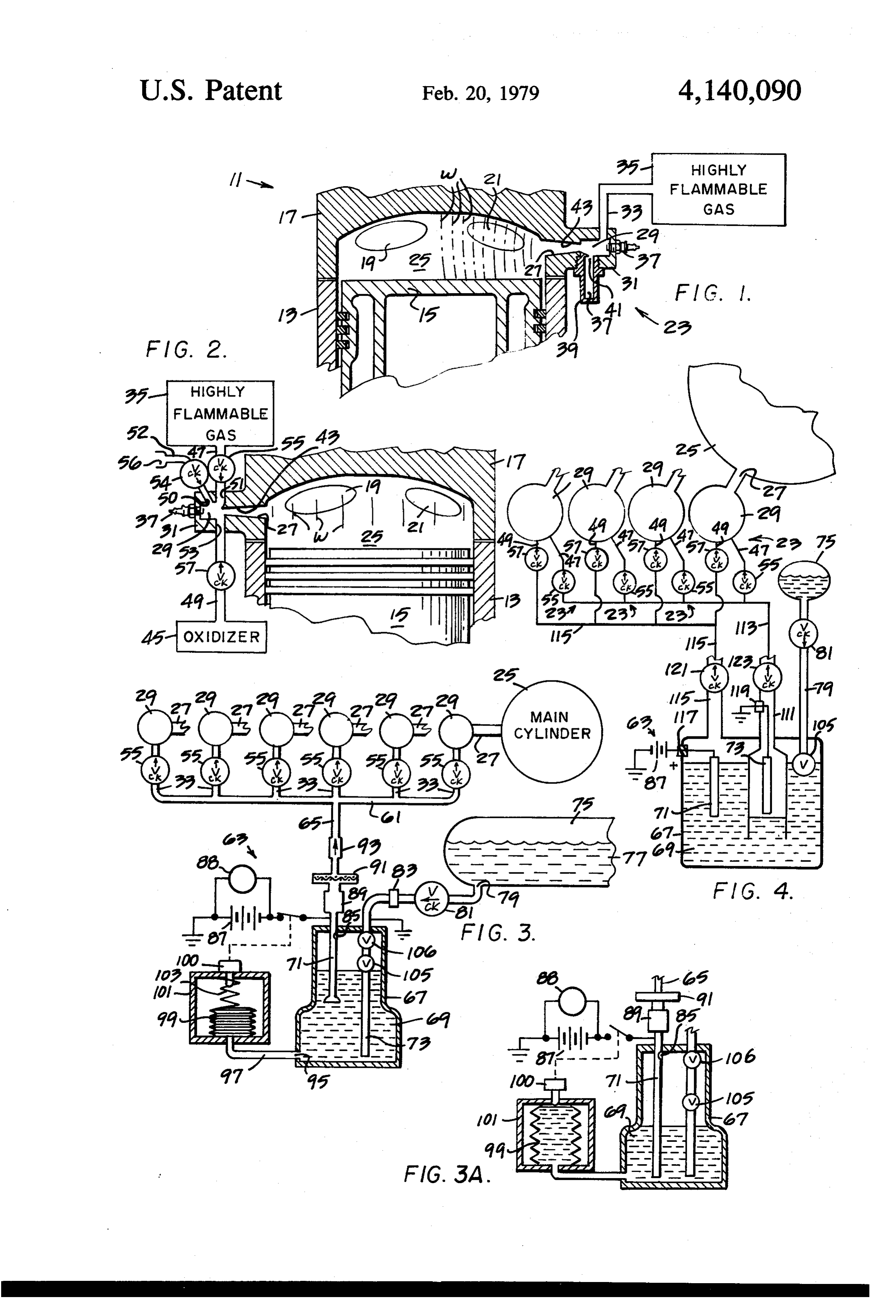
produced by the standing waves, rather than being FIG. 2 is a side elevation view, in cross section, like distributed more or less uniformly across the entire FIG. 1 but showing another embodiment of an engine volume of the main combustion chamber, and this per constructed in accordance with the present invention. mits much higher temperatures to produce a large num In the FIG. 2 embodiment the fuel and oxidizer for the ber of high temperature ignition points spaced through- 5 precombustion chamber are introduced separately into out the main combustion chamber. the precombustion chamber and the precombustion A separate resonant chamber is also associated with chamber has a configuration for producing a velocity of the precombustion chamber mechanism in one embodi injection which corresponds to the critical velocity of ment of the present invention for maximizing the ultra sound to create standing waves and increased efficiency sonic injection of the combustion gases from the pre-10 of ignition and burning in the main combustion cham ber.
combustion chamber into the main combustion cham ber. FIG. 3 is a side elevation view showing a system for In preferred embodiments of the present invention generating a hydrogen-oxygen gas mixture by electrol separate conduits are provided for conducting the 15 ysis in accordance with another embodiment of the highly combustible gaseous fuel and the oxidizer to the present invention. In FIG. 3 the hydrogen and oxygen are conducted to the precombustion chambers by a precombustion chamber so that these two gases are first common mixed in the precombustion chamber itself to maximize manifold.
the safety of operation of the present invention. FIG. 3A is a fragmentary side elevation view show The present invention also incorporates a highly effi ing the generator of FIG. 3 in a condition of operation cient electrolytic gas generator for converting stored 20 in which the electrolytic gas generating process has water to hydrogen and oxygen gases with high electri been stopped by using the pressure of the generated cal efficiency and relatively insignificant use of a liquid gases to force the liquid level of the electrolyte down electrolyte. In this embodiment of the invention potas farFIG. enough to actuate a switch which opens the circuit. 4 is a side elevation view of an electrolytic sium hydroxide or sodium hydroxide is preferably used 25 generating system for generating hydrogen and oxygen as the electrolyte and is used in an enclosed container to separately and for conducting the hydrogen gas to the which water is automatically fed as needed for conver precombustion chambers separate from the oxygen gas. sion to hydrogen and oxygen gases.
The generation of oxygen and hydrogen is automati DESCRIPTION OF THE PREFERRED cally discontinued on engine shut-down by an electrode 30 EMBODIMENTS arrangement incorporated in the electrolytic generator An engine constructed in accordance with one em in some forms of the present invention. In this arrange bodiment of the present invention is indicated generally ment, the pressure of the generated gas is used to de press the level of the liquid electrolyte solution below by the reference numeral 11 in FIG. 1. The engine 11 includes a cylinder 13, a piston 15, a and out of contact with, one electrode after engine is cylinder head 17 (which may have one or more intake shut-down so that no more gas is generated until the and exhaust ports 19 and 21) and precombustion cham engine is again started.
All embodiments of the present invention incorporate ber means 23 for igniting a gaseous fuel (preferably a a safety arrangement for utilizing a highly combustible chambercombustible highly gaseous fuel) in the precombustion gas, such as hydrogen, in a way which assures safety of 40 chamber gases into injecting and then a main the hot precombustion combustion chamber 25 operation. through a port 27.
Internal combustion engine apparatus and methods The main combustion chamber 25 burns a relatively which incorporate the features noted above and which lean fuel-oxident mixture. For example, a conventional are effective to produce the results described above hydrocarbon fuel (such as gasoline) and air mixture can constitute further, specific objects of the present inven- 45 be used. The mixture is conducted into the main com tion. bustion chamber through the intake valve 19. Other and furthur objects of the present invention In accordance with the present invention the precom will be apparent from the following description and bustion ehamber means. 23 comprise a precombustion claims and are illustrated in the accompanying drawings chamber 29 formed within a housing 31. which, by way of illustration, show preferred embodi- 50 A gaseous fuel, such as free hydrogen, carbon mon ments of the present invention and the principles oxide, butane, propane, methane, or ethane or the like is thereof and what are now considered to be the best supplied to the precombustion chamber 29 through a modes contemplated for applying these principles. conduit 33 from a reservoir or generator 35. Other embodiments of the invention embodying the In the precombustion chamber 29 the gaseous fuel is same or equivalent principles may be used and struc- 55 ignited by a spark plug 37, or glow plug or other igni tural changes may be made as desired by those skilled in tion means.
the art without departing from the present invention Because, in the preferred form of the FIG. 1 embodi and the purview of the appended claims. ment, a highly combustible gas is used which has a very BRIEF DESCRIPTION OF THE DRAWINGS 60 broad range of combustibility, it is not necessary to provide carburetion for mixing the highly combustible
FIG. 1 is a side elevation view, in cross section, gas with oxygen, air or another gas containing oxygen. through the top part of a combustion chamber of an Instead, in the FIG. 1 embodiment, enough air is sup engine constructed in accordance with one embodiment plied to the precombustion chamber 29 (by back flow of the present invention. In FIG. 1 a precombustion through the port 27 during the intake stroke) to provide chamber using a highly combustible gas is constructed 65 the necessary ignition and burning of the combustible to have a resonance chamber for producing ultrasonic gas supplied to the precombustion chamber 29 through injection of the products of combustion of the precom the conduit 33. In other embodiments a separate source bustion chamber into the main combustion chamber. of oxygen, air or other oxidant is supplied to the pre
Page 5
combustion chamber 29 and gaseous fuels which are not oxide to air is 32%, and carbon monoxide produces a highly combustible, such as butane, propane and meth flame temperature of 2,925 C. when the percent of ane may be used, as will become more apparent from oxygen by volume in a carbon monoxide-oxygen mix the description to follow. ture is 70%.
To illustrate the broad range of combustibility for By comparison, conventional hydrocarbon fuels pro free hydrogen, for example, the ignition by percent of duce significantly lower flame temperatures. For exam volume for hydrogen in air varies from 4% at the lower ple, gasoline, when burned in air at substantially atmo limit to 74.2% at the upper limit. spheric pressure and in the usual fuel-air mixture ratios The ignition limit by percent of volume for carbon occuring at engine idle operation, produces a flame monoxide in air varies from 12.5% at the lower limit to O temperature of about 1,400 C.
74.2% at the upper limit. The fact that the highly combustible gases burned in By comparison, the ignition limits for most conven the precombustion chamber 29 produce very high flame tional hydrocarbon fuels fall within a very narrow temperatures is another factor that permits the amount range. of gas used in the precombustion chamber 29 and the Benzol (one of the components of gasoline) for exam 15 size of the precombustion chamber mechanism to be ple, has an ignition limit by percent of volume in air of 1.41% at the lower limit and 6.75% at the upper limit. The hot combustion products from the precombus Ethane has ignition limits by percent of volume of tion chamber 29 flow through the port 27 into the main 3.22% at the lower limit and 12.45% at the upper limit. combustion chamber 25 at high velocity as well as at Therefore, normal hydrocarbon fuels must be carbu 20 high temperature, and this produces a desired swirling reted very carefully to provide the proper ratios by and aids in turbulent mixing and helps complete vapori volume with air in order to obtain ignition. zation of any liquid fuel droplets introduced into the Moreover, the comparisons noted immediately above main combustion chamber 25 through the intake valve for hydrocarbon fuel components are actually vapor 19. As a result, the ignition and burning of the hydrocar comparisons which assume that the fuels have been 25 bon fuel in the main combustion chamber 25 is accom completely vaporized. In actual practice, complete va plished more efficiently and more completely than in a porization of such liquid fuels does not occur so that conventional engine system without the precombustion only partial vaporization is obtained, and the ignition chamber of the present invention. levels are even more narrow than listed immediately As a result, the engine can be operated on a leaner above. 30 fuel-air mixture in the main combustion chamber 25 and Because the fuel used for the precombustion chamber this in turn produces more efficiency in operation and 29 is preferably a highly combustible fuel and is a gase less pollutants. Thus, because you have an excess of air, ous fuel, rather than a vaporized liquid fuel, the highly you get less carbon monoxide because the combustion is combustible gaseous fuel ignites easily and within a complete, and you get more complete combustion and broad range of combustibility within the precombustion therefore very low amounts of unburned hydrocarbons. chamber 29. Also, the flame temperature is cooler, because you have Only very small amounts of fuel are required for the an excess of air which is acting as an internal coolant. precombustion chamber 29 since the primary purpose Therefore, the formation of nitrous oxide is prevented of the precombustion chamber is to provide ignition and or maintained very low (since the nitrous oxide is a mixing of the hydrocarbon fuel in the main combustion temperature phenomena relating to combustion cham chamber 25. Because the gaseous fuel burned in the ber temperatures such that higher combustion chamber precombustion chamber 29 need not be supplied in an temperatures tend to produce higher amounts of nitrous amount to provide any significant power output to the oxide).
piston 5, only relatively small amounts of gaseous fuel The precombustion chamber mechanism 23 of the are required; and, accordingly the generation or storing 45 present invention not only provides easy ignition over a of the highly combustible gas and the structural size of broad range of combustibility with the gaseous fuels the precombustion chamber mechanism 23 can be kept used in the present invention, but also produces clean to a minimum. By way of example, in a specific embodi combustion with little or no deposits or undesirable ment of the invention, the precombustion chamber 29 is emissions. For example, when hydrogen is used as a approximately 0.2 inch in internal diameter and about 50 gaseous fuel, the burning of the hydrogen with oxygen 0.2 inch in internal length to provide an internal volume produces only water, and there are absolutely no depos of about 0.006 cubic inches. This can of course be its which can collect on the spark plug 37 or precom smaller or larger. bustion chamber surfaces. Similarly, when carbon non The highly combustible gas burned in the precombus oxide, ethyleneoxide, carbon disulfide, hydrogen sul tion chamber 29 produces very high flame tempera 55 fide, diethyle ether, divinyl ether, acetylene and the like tures. For example, when free hydrogen is used, the are used as the gaseous fuels for the precombustion flame temperature generated is approximately 2,045 C. chamber mechanism 23, the broad range of combustibil when the atmospheric air is used as the oxidant and is ity provided by such gaseous, highly combustible fuels even higher, ranging up to approximately 2,487 C. minimize the formation of undesirable emissions and when the oxidant contains 67% oxygen and ranges up any deposits on the precombustion chamber surfaces. to 2,660 C. when the oxygen content of the mixed fuel In accordance with the present invention, a resonat and oxygen gases is 78% by volume of oxygen. ing chamber 37 is preferably incorporated in the pre Free hydrogen produces the highest flame tempera combustion chamber means 23 for producing standing tures, but high flame temperatures can also be obtained waves W in the main combustion chamber 25. Each by other highly combustible gases, such as carbon mon 65 wave front W of a standing wave produces a region of oxide, propane, butane and the like. high flame front temperatures which serve, in effect, as Carbon monoxide, for example, produces flame tem a plurality of highly effective ignition points in the main peratures of 2,100° C. when the percent of carbon mon combustion chamber 25. The resonance and standing
Page 6
wave pattern also produces increased turbulence for With the present invention a low temperature elec producing the desired mixing in the main combustion. trode plug 37 can be used because very little or no chamber 25. The resonance chamber 37 in the FIG. 1 deposits are formed in the precombustion chamber 29. embodiment is produced by structure which in effect In combustion chambers which burn conventional hy forms a whistle. The structure includes a housing 39 5 drocarbon fuels deposits are formed on the spark plug which defines the internal chamber 37 for the desired surfaces as a normal result of the combustion process wave length, and the inlet to the chamber 37 is provided and the plug must therefore be a high temperature plug by an orifice 41 formed in the upper end of the chamber. to burn off these deposits. Since in the present invention The outlet end of the precombustion chamber 29 is deposits are not formed, high plug temperatures are not preferably formed in the shape of a nozzle 43 having an 10 required to burn off deposits and a low temperature orifice at the throat of the nozzle for maximizing the plug can be used. Using a low temperature plug helps to velocity of the precombustion chamber combustion prevent preignition, and this is an important factor in gases ejected into the main combustion chamber 25. the use of highly combustible gases. Because the size of the precombustion chamber In the present invention, it is possible to use existing, means 23 can be kept to a minimum small size, the spark 15 conventional voltages and yet obtain longer electrode plug 37 itself can be maintained quite small. life because there is less transfer of material from the The spark plug 37 in the present invention can be plug electrodes at the lower temperatures used for the made quite small because of the cleanliness of combus plug in the present invention.
tion in the precombustion chamber structure. With all The FIG. 2 embodiment is similar to the FIG. 1 em of the gaseous fuels of the present invention, there are 20 bodiment described above (and corresponding refer little or no carbon and no lead deposits, and when hy ence numerals have been used for corresponding struc drogen is used there is absolute cleanliness with abso tural features), but the FIG. 2 embodiment incorporates lutely no carbon or lead deposits. a reservoir or generator 45 for the oxidizer. There is no lead deposit with any of the gaseous fuels In the FIG. 2 embodiment the gaseous fuel is con of the present invention because no lead is required for 25 ducted to the prechamber 29 by a conduit 47 and the the combustion process in the precombustion chamber oxidizer, such as oxygen gas, is conducted to the pre 29. combustion chamber 29 through a conduit 49. A sepa Because of the cleanliness of the combustion reaction rate port 51 is formed in the wall structure of the pre within the precombustion chamber 29, there are nd combustion chamber housing 31 for introducing the deposits which can become glowing hot spots to create 30 gaseous fuel, and a separate port 53 is provided for the problems of preignition. As a consequence, then, oxidizer so that the fuel and oxidizer are first mixed smaller precombustion chamber structure and spark together within the precombustion chamber 29 itself. plugs can be used and lower energy ignition systems can The conduit 47 has a check valve 55 for preventing be used. This is an important advantage because the any reverse flow of gas or combustion products from physical size of the electrodes of the spark plug can be 35 the precombustion chamber 29 through the conduit 47, maintained at a minimum with small electrodes. and the conduit 49 has a similar chegk valve 57 for Because, in the present invention the combustion is so preventing reverse flow through the conduit 49. clean, the length of the shunt path can be minimized The nozzle 43 is preferably made to the configuration (that is, virtually no deposits can build up on the shunt of a critical flow nozzle, and the chamber 29 itself has a path on the ceramic, so a relatively short shunt path can configuration producing resonance so that the nozzle be utilized), and much lower voltages and energies can produces the standing waves W in the main combustion be used than the voltages and energies required for chamber 25 as described above with reference to FIG. conventional large spark plugs firing normal hydrocar 1.
bon mixtures and having long shunt paths. The ex Because the flame temperatures are quite high in the tremely small spark plug of the present invention then 45 precombustion chamber 29, the heat soak into the struc operates, in conjunction with the highly combustible ture of the housing 31 can build up to the point where gaseous fuel and oxidizer in the precombustion cham internal air cooling is desirable in some cases. ber, as a highly efficient ignition amplifier (amplifying In the FIG. 2 embodiment a passageway 50 extends both temperature and energy) and projection. The pres through the wall of the housing 31 and connects to a ent invention amplifies the ignition effect of the spark SO conduit 52 which opens to atmosphere. A one-way plug and projects this ignition effect into the main com check valve 54 permits flow from atmosphere to the bustion chamber 19 as an amplified effect at many passageway 50. us points. The amplified ignition effect is projected and An orifice 56 at the inlet end of the conduit 52 regu distributed throughout the main combustion chamber lates the amount of flow into and through the conduit by reason of the very high flame front temperatures, the 55 S2.
high velocity at which the gases from the precombus The orifice 56, conduit 52, check valve 54 and pas tion chamber are injected into the main combustion sageway 50 permit a regulated flow of cooling air to the chamber 25 and the standing wave effect produced by precombustion chamber 29 on the intake stroke of the the ultrasonic generator. piston 15 to provide internal air cooling of the precom The system of the present invention provides a signif. bustion chamber internal surfaces, which can become icant increase in the ignition energy supplied to the critical in cases where free hydrogen is burned with main combustion chamber. One embodiment of the oxygen under vacuum conditions, since under these present invention supplies over one hundred times as conditions the ignition temperature can be as low as much ignition energy as the conventional, existing spark 400 C. at 10mm Mercury. This is a condition where ignition systems currently in use. Furthermore, the 65 preignition can occur if an undesirable amount of heat actual electrical energy required for the spark plug of soak is permitted to accumulate as a result of the ex the present invention is much less than that required for tremely high flame front temperatures generated in the a spark plug of a conventional ignition system. small precombustion chamber structure. Adding atmo
Page 7
spheric air as a dilutant in these conditions of operation tain conditions of operation (when the engine is shut off is beneficial in that the temperature of self ignition of . as will be described in greater detail below). the hydrogen-oxygen air mixture is raised, so that preig A float operated check valve 105 is located in the nition problems become less critical; and the cooling air conduit electrode 73 for shutting off flow of water from inducted thus not only serves to internally air cool the 5 the tank 77 to the enclosed container 67 when the level structure, but raises the self ignition temperature of this of the liquid 69 in the container 67 rises to a certain high particular mix of gases over that which would exist level within the container. This prevents any liquid from being sucked into the opening 85 and into the main without the cooling air. The self ignition temperature is cylinders raised in a substantial amount, in the range of several 10 25 of the engine. hundred degrees Centigrade. y A pressure actuated valve 106 is also located in the FIGS. 3, 3A and 4 show other embodiments of the conduit 73 and closes at a preselected pressure in the present invention in which a precombustion chamber container 67 to permit the level of the liquid 69 to be mechanism 23 is associated with each main cylinder 25 depressed float valve as shown in FIG. 3A without refilling by the
in the same general way as shown in detail above in The liquid 69 is preferably a potassium hydroxide FIGS. 1 and 2; and FIGS. 3 and 4 illustrate details of specific electrolytic generator systems for generating solution or a sodium hydroxide solution for converting hydrogen and oxygen for the individual precombustion the inducted water from the tank 75 to hydrogen and oxygen under the electrolytic action produced by the chamber mechanisms 23.
In the FIG. 3 and FIG. 3A embodiments, the hydro 20 battery 87, electrodes 71 and 73 and the electrolyte of the potassium hydroxide or sodium hydroxide solution.
gen and oxygen are supplied to each inlet conduit 33 by This a common manifold 61. The inlet manifold 61 is in turn and istype of electrolytic generator is highly efficient effective to convert the water to free hydrogen connected to an electrolytic generator 63 by a conduit 65. The electrolytic generator 63 includes an enclosed and oxygen with very little or no loss of electrolyte itself and with the minimum consumption of electrical container 67. The enclosed container 67 is partially 25 energy from the battery 87. : filled with a liquid 69. A first electrode 71 and a second In the preferred embodiment of the electrolytic gen electrode 73 extend downward from the upper end of erator 63 a 15% solution of sodium hydroxide and the container into the liquid 69 in the mode of operation water illustrated in FIG. 3. Each electrode is a hollow pipe water isorused. a 25% solution of potassium hydroxide and Since the production, in kilowatt hours, is which also serves as a conduit.
A water storage tank 75 is partially filled with water sodium hydroxide,for about 8% greater potassium hydroxide than it is for 77 subjected to atmospheric pressure on the upper sur electrolyte solution. However,hydroxide potassium is the preferred sodium hydroxide is less face of the water. An outlet 79 in the lower part of the expensive than potassium, hydroxide and is therefore storage tank 75 is connected to the conduit electrode 73 more commonly used.
and contain a one-way check valve 81. The conduit 35 Since the details of the electro-chemical conversion electrode 73 is connected to ground as illustrated and itself are well known, such details will not be described may also preferably include an electrical isolator 83. further at this point.
The conduit electrode 71 is formed with an opening In the operation of the system shown in FIGS. 3 and 85 within the enclosed container 67 near the top inside 3A, the intake vacuum produced in the main cylinders surface of the container for conducting gas generated 40 25 acts in conjunction with the atmospheric pressure within the container above the surface of the liquid 69 exerted on the water 77 in the tank 75 to draw the hy through the opening 85 and to the conduit 65. drogen and oxygen gas generated in the electrolytic The electrode conduit 71 is connected to a battery 87 generator 63 through the opening 85 and the conduit 65, and an electrical isolator 89 is located on the conduit inlet manifold 61 and intake conduit 33 to the individual beyond the connection to the battery. 45 precombustion chambers. 29.
A flame retardant screen 91 is interposed in the con In the operation of the FIGS. 3 and 3A embodiment, duit 65 to prevent any flashback into the gases gener whatever residual gases remain in the precombustion ated in the enclosed container 67. Flashback can also be chamber 29 after the completion of the exhauststroke of prevented by proper dimensioning of the conduit and the main piston 15 are drawn into the main combustion choice of materials. Highly heat conductive materials 50 chamber 25 on the intake stroke of the piston 15 so that and high surface areas with small diameter opening any residual water vapor in the precombustion chamber (parallel tubes if necessary) prevent flashback. 29 resulting from combustion of the hydrogen and oxy A one way check valve 93 is also preferably located . gen in the precombustion chamber is inducted into the in the conduit 65 to prevent any reverse flow of gases. main combustion chamber 25 with desirable results. The lower end of the enclosed container 67 has an 55 The hydrogen and oxygen then drawn into the precom opening 95 which connects to a conduit 97, and the bustion chambers 29 are drawn in as dry gases, and this conduit 97 is in turn connected to the interior of a bei enhances the clean, efficient combustion in the precom lows 99. The bellows 99 is mounted within a housing bustion chambers 29 as described above. 101, and a biasing spring 103 exerts a biasing force on This also simplifies ignition because the gases are dry. the bellows 99 in a direction which tends to force the However, even if any residual water vapor should contents of the bellows 99 back into the interior of the remain in the precombustion chambers 29, there would enclosed container 67. The bellows 99 thus serves as a be minimal detrimental effect on the forming of the flexible walled, spring biased accumulator for accumul electric spark because the pure water formed is a poor lating a certain amount of liquid flow from the enclosed conductor.
container 67 (as illustrated in FIG. 3A) to permit the 65 The high level check valve 105 prevents the liquid level of the liquid 69 to drop until the bellows fills and level in the electrolytic generator 67 from rising to the actuates a switch 100 to break electrical contact be point where the liquid itself can pass into the outlet tween the electrode 71 and the electrode 73 under cer opening 85, and as a result only the generated hydrogen
Page 8
and oxygen gas mixture can flow to the engine, regard erated around the electrode 73, and the upper end of less of any vacuum condition produced in the engine. this collector housing 111 is connected to a conduit 113 The accumulator 99 permits a sufficient amount of which serves as an inlet manifold for the individual liquid 69 to be transferred from the enclosed electro conduits 47 for the precombustion chambers 29. lytic generator 67 to the accumulator 99 on engine A conduit 115 connects to the interior of the enclosed shut-down to fill the bellows and to actuate a switch container 67 for collecting and conducting the gener 100. This opens the circuit and stops electrical conduc ated oxygen, and this conduit 115 serves as an inlet tance between the electrodes 71 and 73 to stop genera manifold for the individual conduits 49 of the precom tion of hydrogen and oxygen. bustion chambers 29. . . When the engine is shut off, the spring forces of the 10 The electrode 71 is connected to the positive terminal check valves 55 are high enough to accomodate the of the battery 87 through an insulator 117, and the elec change in static head of the liquid between that illus trode 73 is connected to ground through an insulator trated in FIG.3 and that illustrated in FIG. 3A so that 19. s the pressure of the gases generated in the enclosed con In the operation of the system shown in FIG. 4 the tainer 67 build up sufficiently to force the liquid level 15 electrolytic cell 67 produces oxygen gas and hydrogen down to the position illustrated in FIG. 3A. In this gas around the respective electrodes 71 and 73, and condition of operation the electrical conductance be these gases are conducted to the individual precombus tween the electrodes 71 and 73 is broken and no further tion chambers 29.
gas is generated; and the system remains in the condi tion illustrated in FIG. 3A until the engine has started 20 57When cause the engine is shut off, the check valves 55 and the pressure within the housing 11 to build up up again and the intake vacuum is generated in main until the level cylinders 25 to initiate the cycle of operation described the end of theofelectrode the fluid in the housing is forced below 73 to break the electrical con above.
This differential between the intake vacuum and the ducting path between the electrodes 71 and 73; and this atmospheric pressure in the water tank 75 occurs 25 causes the generation of the oxygen-hydrogen gases to quickly during the initial cranking of the engine on end. On engine start-up, the difference between the vac starting. Since this immediately produces hydrogen and uum conditions in the lines 113 and 115 and the super oxygen well within the combustible range, the engine will start immediately (because of the stored hydrogen atmospheric tainer 67 pressure existing in the interior of the con (generated at the time of shut-down) immedi oxygen gas mixture which had been previously gener 30 ated) with very little or no enrichment required by way ately raises the level of the liquid within the collector housing 111 to start the electrolytic generation of the
In the FIG. 3 embodiment the hydrogen is mixed hydrogen hydrogen and oxygen gases. At the same time the stored with the oxygen in the common conduit 65. The mixed and oxygen gases in the container 67 are gases will not ignite in this conduit 65because the flash 35 sucked into the precombustion chambers 29. point of hydrogen under such conditions is about 800 alsoThebeelectrolytic generator 63 shown in FIG. 4 can used for the common manifold 61 structure
In addition to the hydrogen generated by the cell 63, shown in FIG.3 by adding check valves 121 and 123 as the hydrogen generated by the automobile battery can illustrated in FIG. 4 and then joining conduits 113 and also be collected and utilized in the precombustion 115 in a common manifold before the flame retardant chambers 29. - screen 91 of FIG. 3. .
The battery 87 for the electrolytic cell 63 can be the While the electrolytic cells shown in FIGS. 3 and 4 same as the existing automobile battery so that the exist have been illustrated assingle cells, in practice, the cells ing automobile generator or alternator and associated are multiple cells which utilize the conventional 12-volt voltage regulator can be used to supply the energy 45 ignition system of existing automobiles with five to six needed for the conversion of the water to hydrogen and individual cells so that each individual cell operates at oxygen. its most efficient voltage of 2 to 2 volts. A conversion unit 88 can also be connected in parallel It is an important feature of the present invention that with the battery 87 as illustrated in FIG. 3. The conver while a highly combustible and highly flamable gas is sion unit 88 operates off the waste heat in the engine 50 used for the precombustion chamber, the highly com exhaust to convert a part of that waste heat to electric bustible gas is used in a way that insures safe operation. ity for supplying the electric power for the electrolytic In the preferred form of the present invention utilizing cell. hydrogen as the fuel for the combustion chamber, the Another embodiment of an electrolytic generator 63 hydrogen is preferably handled in conduit structure for is illustrated in FIG. 4. In the FIG. 4 embodiment the 55 the oxygen, and the hydrogen is maintained separated electrolytic cell 63 includes an enclosed container 67 from the oxygen at all times up to the actual mixing of which is partially filled with an electrolyte 69. The the hydrogen and oxygen within the interior of the electrolyte 69 is preferably a potassium hydroxide or precombustion chamber itself. This minimizes any dan sodium hydroxide solution with added water for gener ger from leaks or breaks in the fuel conduit structure. ating the hydrogen and oxygen gases. 60 It is another important feature of the present inven The electrolytic generator includes electrodes 71 and tion that the feed of highly combustible gas is dependent 73 connected with an electrical field produced by a upon producing a vacuum condition so that the differ battery 87 in the manner illustrated. Water is added to ence between the produced vacuum and the existing the container 67 through a conduit 79 and a high level atmospheric pressure will produce the feed pressure check valve 105 in the same way as illustrated in FIG. differential. Thus, if there is a line break, the vacuum is 3. lost and feed pressure differential is broken and the A collector housing 111 extends into the interior of worst that could happen is a dilution of air within the the enclosed container 67 for collecting hydrogen gen gas at the point of the break.
Page 9
While I have illustrated and described the preferred response to an increase of pressure of the gas generated embodiments of my invention, it is to be understood in the electrolytic cell.
that these are capable of variation and modification, and 10, The invention defined in claim 7 including gener I therefore do not wish to be limited to the precise ating the free hydrogen by electrolysis in an electrolytic details set forth, but desire to avail myself of such 5 cell which produces hydrogen and oxygen from water changes and alterations as fall within the purview of the and an electrolyte and including automatically adding following claims. .. water to the cell as the water is consumed in the conver I claim: - .. . . . . . ; -sion to oxygen and hydrogen. 1. A method of operating an internal combustion 11. The invention defined in claim 1 including pro engine of the kind in which a fuel is mixed with an 10 ducing shock waves in the gases of the combustion oxidant and ignited in a main combustion chamber to process as the gases from combustion process are di produce the power output of the engine, said method rected from the precombustion chamber into the main comprising, feeding a conventional, primary fuel mixed combustion chamber to provide a plurality of distrib with an oxidant into a main combustion chamber in an uted, high temperature ignition points throughout the amount sufficient to provide by combustion of the pri 15" main combustion chamber.
mary fuel all of the power required for operation of the 12. The invention defined in claim 11 wherein the engine and at lean fuel-oxidant ratios for efficient com shock waves are produced by an ultrasonic chamber bustion with low emissions, feeding a highly combusti associated with the precombustion chamber. ble gaseous fuel and a gas containing oxygen into a 20 13. The invention defined in claim 1 including intro precombustion chamber, feeding the gaseous fuel to the ducing cooling and dilutant air into the precombustion precombustion chamber in a small amount sufficient chamber to maintain the temperature of the precombus only to provide heat and turbulence for ignition of the tion chamber below the lower ignition level of the fuel primary fuel and insufficient to produce any significant and oxidant mixture in the precombustion chamber, and amount of useable power in the main combustion cham 25 initiating ignition in the precombustion chamber by an ber, said highly combustible gaseous fuel having a electric ignition device.
broad enough range of combustibility to permit ignition 14. An internal combustion engine comprising a main in the precombustion chamber without the need to combustion chamber, primary fuel supply means for provide carburetion of the gaseous fuel with the gas supplying a primary fuel-oxidant mixture to the main containing oxygen, igniting the gaseous fuel in the pre 30 combustion chamber in an amount sufficient to produce combustion chamber, and then directing the combus by combustion of the primary fuel all of the power tion gases from the precombustion chamber into the required for operation of the engine and at lean fuel-oxi main combustion chamber to ignite the fuel-oxidant dant ratios for efficient combustion with low emissions, mixture in the main combustion chamber, burning the and precombustion chamber means for feeding a gase primary fuel in the main combustion chamber at lean 35 ous fuel to a precombustion chamber and for igniting fuel-oxidant ratios to produce efficient combustion with the gaseous fuel in the precombustion chamber and for low emissions, and wherein the gaseous fuel is selected directing the gases from the combustion process from from the group comprising hydrogen and carbon mon the precombustion chamber into the main combustion oxide. - chamber to ignite the fuel-oxidant mixture in the main 2. The invention defined in claim 1 wherein the combustion chamber, and including electrolytic genera highly combustible gaseous fuel is free hydrogen. tor means for generating free hydrogen and free oxygen 3. The invention defined in claim 2 including generat and conduit means for conducting the generated free ing free hydrogen and also generating free oxygen and hydrogen and free oxygen to the precombustion cham burning the hydrogen with the oxygen in the precom ber and wherein the electrolytic generator means are bustion chamber to produce water. .. 45 constructed to generate the free hydrogen in a small 4. The invention defined in claim 1 including burning amount sufficient only to provide heat and turbulence the gaseous fuel in a stoichiometric mixture in the pre for ignition of the primary fuel and insufficient to pro combustion chamber. duce any significant amount of useable power in the 5. The invention defined in claim 1 including con main combustion chamber. - ducting the gaseous fuel to the precombustion chamber 50 15. The invention defined in claim 14 including check through a first conduit and conducting an oxygen con valve means in the conduit means for preventing a re taining gas to the precombustion chamber through a verse flow of gases from the precombustion chamber second conduit and preventing any reverse flow of back through said conduits.
gases from the precombustion chamber back through 16. The invention defined in claim 14 including flame said conduits. . .. .. 55 screen means for preventing flashback of the combus 6. The invention defined in claim 5 including prevent tion process through the conduit means. ing flash back of the combustion process through con 17. The invention defined in claim 14 wherein the duit structure conveying the highly combustible gas. electrolytic generator means comprise a cell for react 7. The invention defined in claim 1 including generat ing water with one of a potassium hydroxide and so ing free hydrogen by electrolysis and conducting the 60 dium hydroxide mixture between electrodes under the generated hydrogen to the precombustion chamber. influence of an electric field. 8. The invention defined in claim 7 including generat 18. The invention defined in claim 14 including shock ing hydrogen and oxygen by reacting water with one of wave means for producing shock waves in the combus a potassium hydroxide and sodium hydroxide mixture in tion gases as the combustion gases are directed from the a cell under the influence of an electric field. 65 combustion chamber into the main combustion chamber 9. The invention defined in claim 7 including generat to provide a plurality of distributed, high temperature ing the hydrogen in an electrolytic cell and stopping the ignition points throughout the main combustion cham generation of the hydrogen in the electrolytic cell in ber.
Page 10
19. The invention defined in claim 18 wherein the gine and at lean fuel-oxidant ratios for efficient stock wave means include an ultrasonic chamber associ combustion with low emissions, ated with the precombustion chamber. . feeding at a pressure not substantially greater than 20. The invention defined in claim 14 including cool atmosphere, a highly combustible gaseous fuel ing means for introducing cooling and dilutant air into 5 selected from the group consisting of hydrogen the precombustion chamber to maintain the tempera and carbon monoxide, and a gas containing oxygen ture of the precombustion chamber below the lower.. into a precombustion chamber, ignition level of the fuel and oxidant mixture in the feeding the gaseous fuel to the precombustion cham precombustion chamber and including electric spark : ber, in a small amount sufficient only to provide means for initiating ignition in the precombustion cham- 10 heat and turbulence for ignition of the primary fuel ber by an electric ignition device. and insufficient to produce any significant amount 21. A method of operating an internal combustion ofuseable power in the main combustion chamber, engine of the kind having an induction cycle and in said, highly combustible gaseous fuel having a which a fuel is mixed with an oxidant and ignited in a broad enough range of combustibility to permit main combustion chamber to produce the power output 15 ignition in the precombustion chamber without the of the engine, said method comprising: : ... need to provide carburetion of the gaseous fuel drawing in a conventional, primary fuel mixed with with the gas containing oxygen, an oxidant into a main combustion chamber igniting the gaseous fuel in the precombustion cham througout the induction cycle in an amount suffi ber, cient to provide by combustion of the primary fuel 20 then directing the combustion gases from the pre all of the power required for operation of the en combustion chamber into the main combustion gine and at lean fuel-oxidant ratios for efficient chamber to ignite the fuel and oxidant in the main combustion with low emissions, combustion chamber, and drawing in throughout the induction cycle a highly burning the primary fuel in the main combustion combustible gaseous fuel selected from the group 25 chamber at lean fuel-oxidant ratios to produce effi consisting of hydrogen and carbon monoxide, and cient combustion with low emissions. a gas containing oxygen into a precombustion 23. An internal combustion engine comprising: chamber, a main combustion chamber, feeding the gaseous fuel to the precombustion cham primary fuel supply means for supplying a primary ber in a small amount sufficient only to provide 30 fuel-oxidant mixture to the main combustion cham heat and turbulence for ignition of the primary fuel ber in an amount sufficient to produce by combus and insufficient to produce any significant amount tion of the primary fuel all of the power required ofuseable power in the main combustion chamber, for operation of the engine and at lean fuel-oxidant said highly combustible gaseous fuel having a ratios for efficient combustion with low emissions, broad enough range of combustibility to permit 35 a precombustion chamber, ignition in the precombustion chamber without the means for feeding, at a pressure not substantially need to provide carburetion of the gaseous fuel greater than atmospheric, a gaseous fuel to a pre with the gas containing oxygen, combustion chamber, igniting the gaseous fuel in the precombustion cham means for igniting the gaseous fuel in the precombus ber, 40 tion chamber, then directing the combustion gases from the pre means for directing the gases from the combustion combustion chamber into the main combustion process from the precombustion chamber into the chamber to ignite the fuel-oxidant mixture in the main combustion chamber to ignite the fuel-oxi main combustion chamber, and dant mixture in the main combustion chamber, burning the primary fuel in the main combustion 45 electrolytic generator means for generating free hy chamber at lean fuel-oxidant ratios to produce effi drogen and free oxygen, cient combustion with low emissions. conduit means for conducting the generated free 22. A method of operating an internal combustion hydrogen and free oxygen to the precombustion engine of the kind in which a fuel is mixed with an chamber via said means for feeding, oxidant and ignited in a main combustion chamber to 50 said electrolytic generator means being constructed produce the power output of the engine, said method to generate the free hydrogen in a small amount comprising: sufficient only to provide heat and turbulence for feeding an oxidant and a conventional, primary fuel ignition of the primary fuel and insufficient to pro into a main combustion chamber in amounts suffi duce any significant amount of useable power in cient to provide by combustion of the primary fuel 55 the main combustion chamber.
all of the power required for operation of the en
Provenance
- Collection
- Cited prior art
- Original PDF
- patentimages.storage.googleapis.com →
- Filed
- 1975-10-17
- Pages
- 10
- Method
- pdftotext (the PDF's own text layer) + pdftoppm 300dpi page scans
- Source
- Google Patents bibliographic record
- Granted
- 1979-02-20
- Inventors
- John E. Lindberg; OWEN WICKERSHAM AND ERICKSON PC
- Transcribed from
- patentimages.storage.googleapis.com →