patent · US6311648
Hydrogen-oxygen/hydrocarbon fuel system for internal combustion engine
6 November 2001
Page 1 — bibliographic record
(12) United States Patent (10) Patent No.: US 6,311,648 B1 Larocque (45) Date of Patent: Nov. 6, 2001
(54) HYDROGEN-OXYGEN/HYDROCARBON 4,362,137 12/1982 O'Hare. FUEL SYSTEM FOR INTERNAL 4,520,763 6/1985 Lynch et al.. COMBUSTION ENGINE 5,399,251 3/1995 Nakamats ................................. 123/3
(76) Inventor: Jean-Louis Larocque, 195, rue des OTHER PUBLICATIONS Frenes, Pointe-aux-Trembles, Québec
(CA), H1B 1X7 The Economist (Dec., 1999) Space-age soot.
(*) Notice: Subject to any disclaimer, the term of this * cited by examiner patent is extended or adjusted under 35
U.S.C. 154(b) by 0 days. Primary Examiner Tony M. Argenbright
Assistant Examiner Hyder Ali (21) Appl. No.: 09/507,734 (57) ABSTRACT (22) Filed: Feb. 22, 2000 A device for injection of molecular hydrogen and oxygen (51) Int. Cl." ........................................................ C25B 1/02 into the combustion chambers of a gasoline engine, along (52) U.S. Cl 123/3 with the fuel-air mixture, to improve fuel efficiency and to -rry reduce and in Some cases eliminate engine emissions. The (58) Field of Search ................................. 123/3, 2. hydrogen-oxygen/hydrocarbon fuel System includes: a water Source; an electrolytic chamber, an anode and a cathode (56) References Cited mounted into the chamber in closely spaced fashion from one another; two fluid lines to fluidingly connect the water
9/1975 Rupe . power Source, for electrically charging the anode and cath 4,181,100 1/1980 Yamane et al.. ode.
4,271,793 * 6/1981 Valdespino ............................... 123/3 17 Claims, 6 Drawing Sheets
Page 2
Drawing sheet — no readable text.
Page 3
Drawing sheet — no readable text.
Page 4
Drawing sheet — no readable text.
Page 5
Drawing sheet — no readable text.
Page 6
Drawing sheet — no readable text.
Page 7
Drawing sheet — no readable text.
Page 8
HYDROGEN-OXYGEN/HYDROCARBON hydrocarbon fuel System for enhancing the efficiency of an FUEL SYSTEM FOR INTERNAL internal combustion engine by Supplying a mixture of hydro COMBUSTION ENGINE gen and oxygen gases and liquid hydrocarbon fuel to the fuel line of this internal combustion engine, Said fuel System
FIELD OF THE INVENTION 5 comprising:
This invention relates to device for enhancing fuel com a) a water Source;
bustion in an internal combustion engine, while improving b) an electrolytic member defining a main liquid chamber the engine efficiency and eliminating at least one toxic having a gas bell therein, Said water chamber and gas by-product from its combustion. bell being in liquid communication with one another 1O under communicating vessels principle;
BACKGROUND OF THE INVENTION c) an anode bar and a cathode bar mounted into Said gas Major industrial countries in the World now have regula bell in closely Spaced fashion from one another; a first tions relating to the level of exhaust emissions from fluid line, fluidingly interconnecting Said water Source automobiles, which are imposing progressively reduced 15 to Said main liquid chamber; permitted levels of internal combustion engine emissions. d) a second fluid line, coupled to said gas bell for This in turn increases the demand for greater control of the fluidingly interconnecting Said gas bell to the fuel line; combustion process of the internal combustion engines. and
U.S. Pat. No. 3,906,913 issued in September 1975 to the e) an electrical power Source, for electrically charging CALIFORNIAINSTITUTE OF TECHNOLOGY, discloses Said anode bar and Said cathode bar, wherein molecular a device for mixing hydrogen with hydrocarbon fuel and air hydrogen and oxygen generated from electrolytic Sepa for use in the internal combustion engine of an automobile. ration of the body of water inside Said gas bell escapes However, such device requires a substantial “on-board” in gaseous State from Said gas bell through said Second hydrogen generating capacity, to meet the large consumption fluid line, for displacement toward and into the fuel line of hydrogen, which consumes energy, occupies valuable 25 and for admixing with the hydrocarbon fuel. Space and adds weight to the vehicle. More Specifically, the invention as disclosed consists of a hydrogen-oxygen/hydrocarbon fuel System for enhancing
Australian company ORBITAL ENGINE COMPANY the efficiency of the internal combustion engine of an automobile by Supplying a mixture of hydrogen and oxygen
(AUSTRALIA) Pty, Limited, discloses a fuel/gas delivery gases and liquid hydrocarbon fuel to the fuel line of this System for use with an internal combustion engine, in which internal combustion engine, Said fuel System comprising: hydrogen is mixed with hydrocarbon fuel for introduction a) a water Source;
into the combustion chamber of the engine. In this patent, b) an electrolytic chamber having an outer housing and an the hydrogen is delivered to the combustion chamber only inner housing, Said outer housing having a Sealed when the engine is operating in a Selected low to medium flooring and Said inner housing having a bottom mouth, load range. Moreover, the injection of the hydrogen is 35 a hanging member fixedly interconnecting Said inner enabled directly into the combustion chamber, which occurs and Outer housings and Supporting Said inner housing independently and later than the fuel delivery; therefore, Spacedly over Said outer housing flooring wherein a only relatively Small amounts of hydrogen are required to achieve the desired improvement in the ignitability of the spacing gap is defined between Said inner housing fuel/air mixture. Substantial improvement in the combustion 40 bottom mouth and Said outer housing flooring, and an process is claimed to be achieved with as little as 2% anode and a cathode mounted into Said inner housing in hydrogen injection in relation to the fuel charge. The low closely spaced fashion from one another; hydrogen usage thus enabled enhances the possibility of c) a first fluid line, fluidingly interconnecting said water providing an economical means of producing Sufficient Source to Said outer housing, quantities of hydrogen on-board an automobile. A claimed 45 d) a Second fluid line, coupled to said inner housing for advantage is that the hydrocarbon (HC) and the toxic carbon fluidingly interconnecting Said inner housing to the fuel monoxide (CO) contents of the exhaust gas are reduced, but tank, not eliminated. e) an electrical power Source, for electrically charging Said anode and cathode, wherein molecular hydrogen
OBJECTS OF THE INVENTION 50 and oxygen generated from electrolytic Separation of An important object of the invention is to improve upon the body of water inside Said inner housing escapes the fuel/gas delivery system described in U.S. Pat. No. from Said electrolytic chamber through Said Second 5,546,902, Supra, by completely eliminating the toxic CO fluid line, for displacement toward and into the fuel by-products from automobile internal combustion engines. 55 tank of the automobile and for admixing with the A general object of the invention is to enhance the hydrocarbon fuel in the fuel tank. Preferably, Said water Source consists of Salt water, pref combustion process and increase the efficiency of internal erably of a concentration combustion engines by reducing the level of exhaust emis Water. of about 160 grams per liter of Sions from the automobile internal combustion engine. The water source should be positioned higher relative to An object of the invention is to decrease fuel consumption 60 Said electrolytic chamber, whereby Said water is gravity fed of automobiles with internal combustion engines. to Said electrolytic chamber.
A further object of the invention is to increase the trav It is envisioned that Said Second fluid line communicates elling range of the automobile for a given Volume of fuel. with Said inner housing via an acceSS port, and further
SUMMARY OF THE INVENTION
including a buoyancy member, installed into Said inner 65 housing in register with Said access port for Sealing the latter
In accordance with the objects of the invention, the upon Said inner housing becoming completely filled to invention relates generally Speaking to a hydrogen-oxygen/ capacity with water.
Page 9
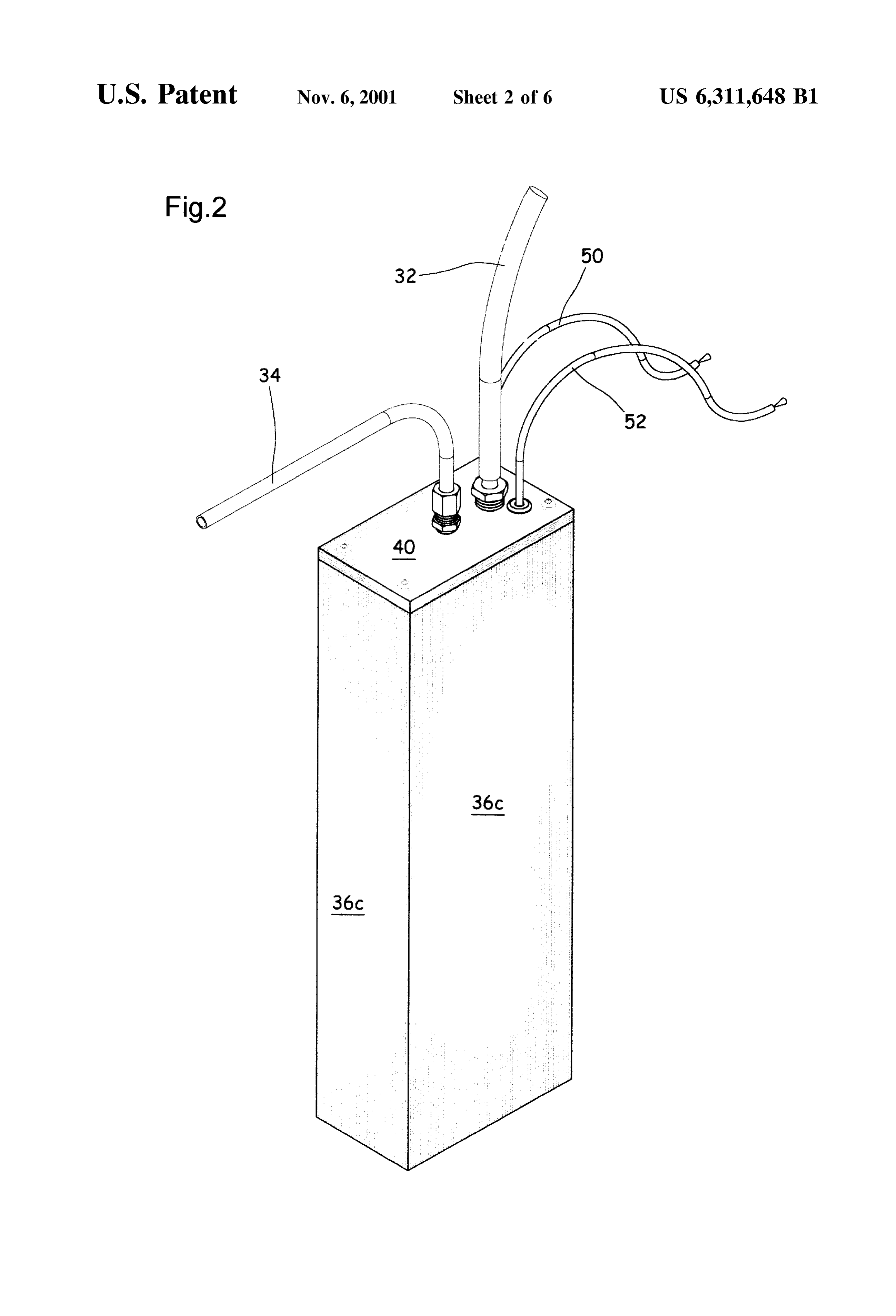
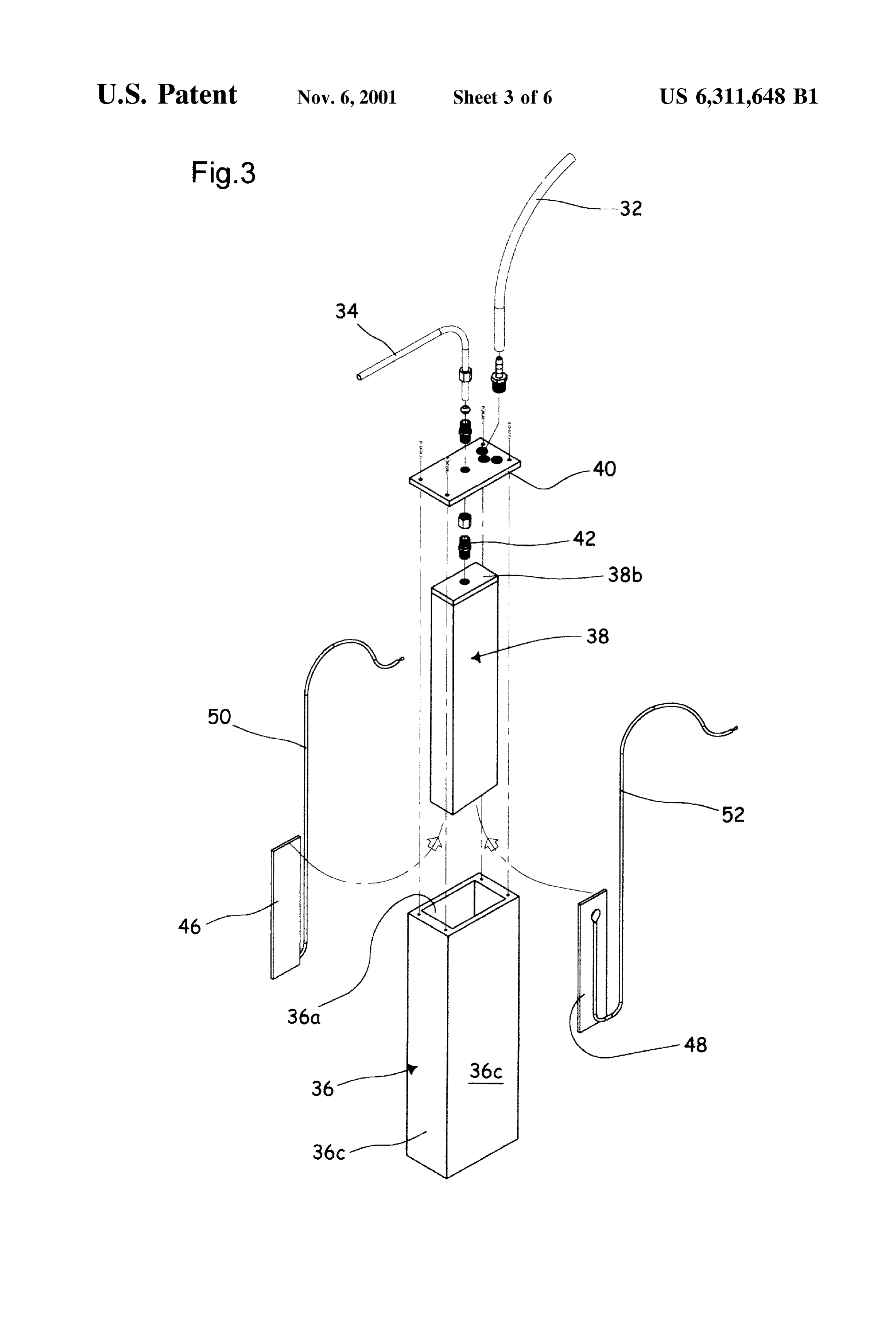
Preferably, a water filter is mounted to said second fluid 6 millimeters (mm). Salt-water tank 30 should be positioned line for preventing accidental liquid water Seeping from Said at a higher position relative to electrolytic chamber 28, for inner housing into the fuel tank. enabling automatic gravity feed of Salt water into chamber Said anode and cathode may each consist of a flat metallic 28. A second flexible line 34 fluidingly interconnects the panel made from a material Selected from the group com electrolytic chamber 28, to the gaZ pump intake Spout 24a of prising brass and graphite, StainleSS Steel, Silver and copper; fuel tank 24, for a purpose set forth hereinbelow. but graphite for anode and brass for cathode are preferred. The electrolytic chamber 28 illustrated in FIGS. 2-6 Said anode and cathode panels preferably extend parallel to includes a first larger box-like housing 36, having a top one another and are spaced from one another by about 2 to mouth 36A, and a second smaller box-like housing 38 4 millimeters (mm), but preferably 3 mm. having a bottom mouth 38A and lodged inside the hollow of An electrically insulating sheath member may be fitted to the larger housing 36. Outer housing 36 includes a bottom an intermediate Section of Said Second fluid line for prevent flooring 36B, and four Side walls 36C in Sealing engagement ing accidental transmission of electric current from Said with one another and with the flooring 36B. Outer housing electrolytic chamber to the fuel tank. 36 is longer and diametrally larger than inner housing 38. A Preferably, there is further included a fuse relay system, 15 lid 40 releasably seals the top mouth 36A of outer housing, intermediate Said electrical power Source and Said anode and and is spacedly connected to the top end wall 38B of the cathode panels, Said fuse relay System preventing electric inner housing 38 by a tubular connector 42, wherein the current from Said electrical power Source to reach Said anode inner housing 38 hangs Spacedly over the outer housing and cathode panels when the internal combustion engine is flooring 36B whereby a spacing gap 44 is defined between not running. the bottom mouth 38A of inner housing 38 and the under The present invention also relates to the combination of lying flooring 36B of outer housing 36. Preferably, housings an automobile with the above-noted hydrogen-oxygen/ 36, 38 are made from plexiglass, which could be transparent hydrocarbon fuel system fitted inside the automobile. plexiglass for enabling See-through inspection for mainte
BRIEF DESCRIPTION OF THE DRAWINGS
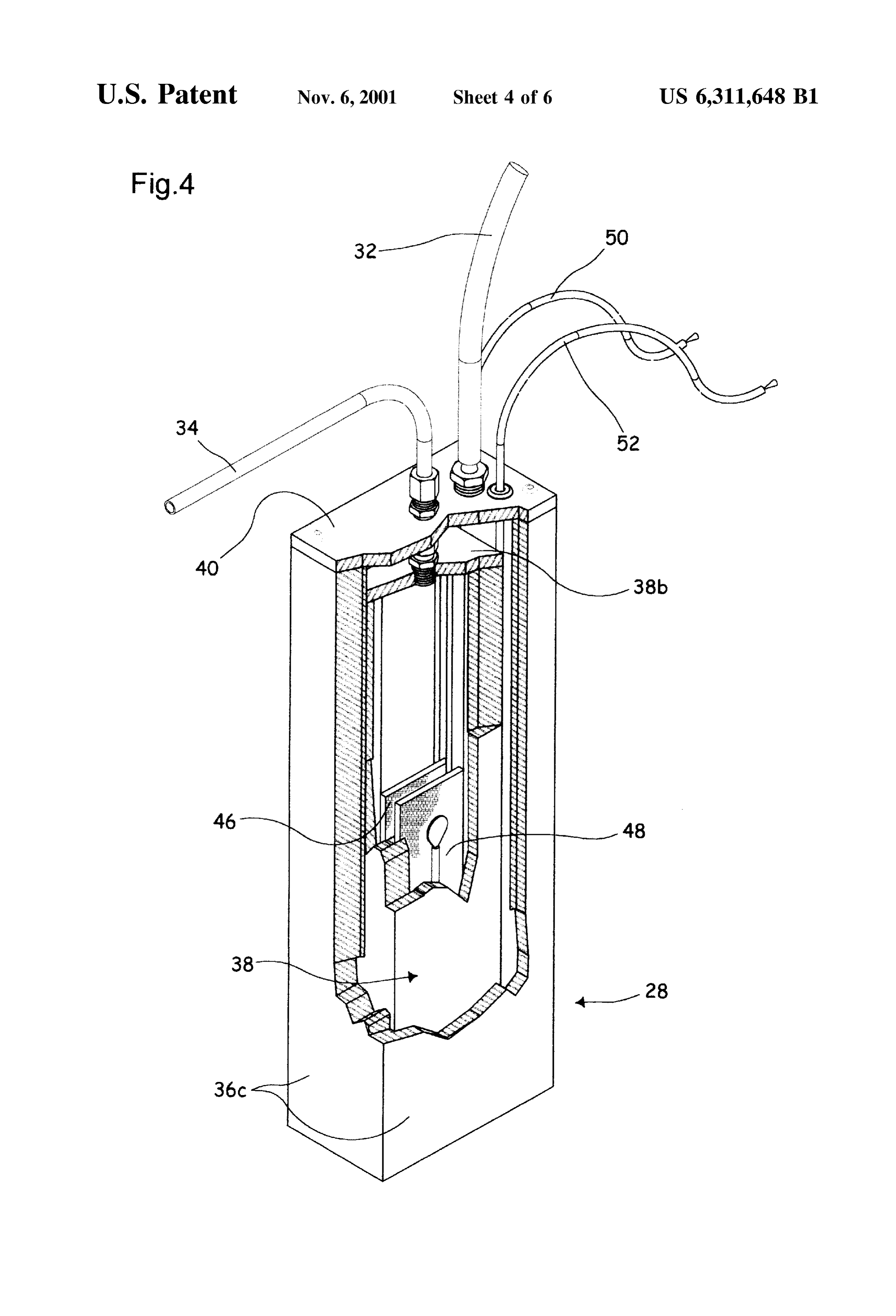
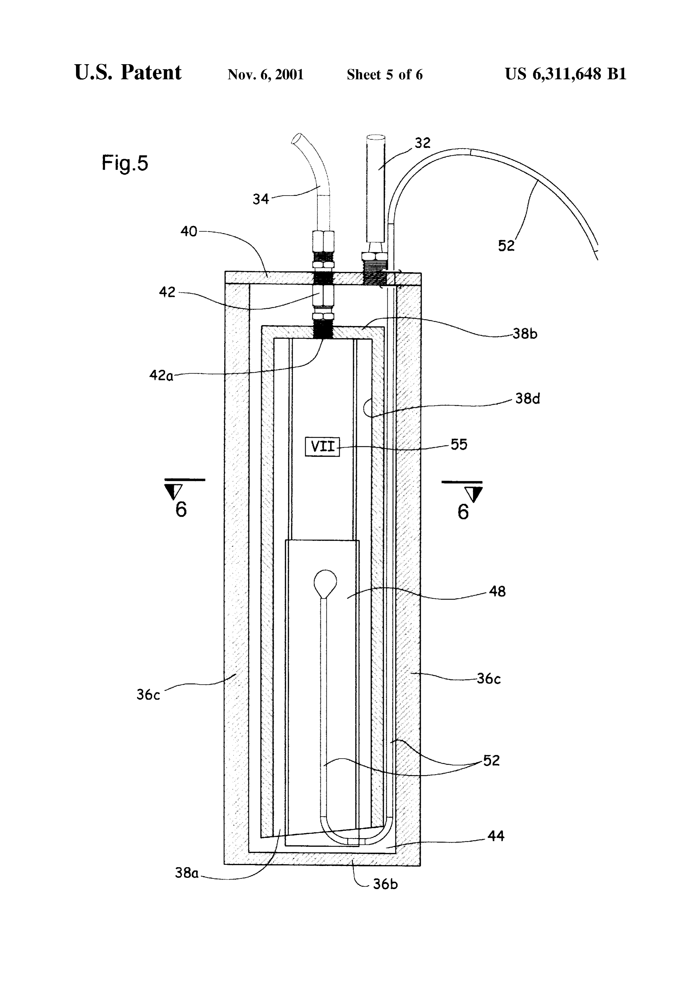
nance. The size of chamber 28 may be for example about 8 25 centimeters (cm) wide, 4 cm deep, and 28 cm high.
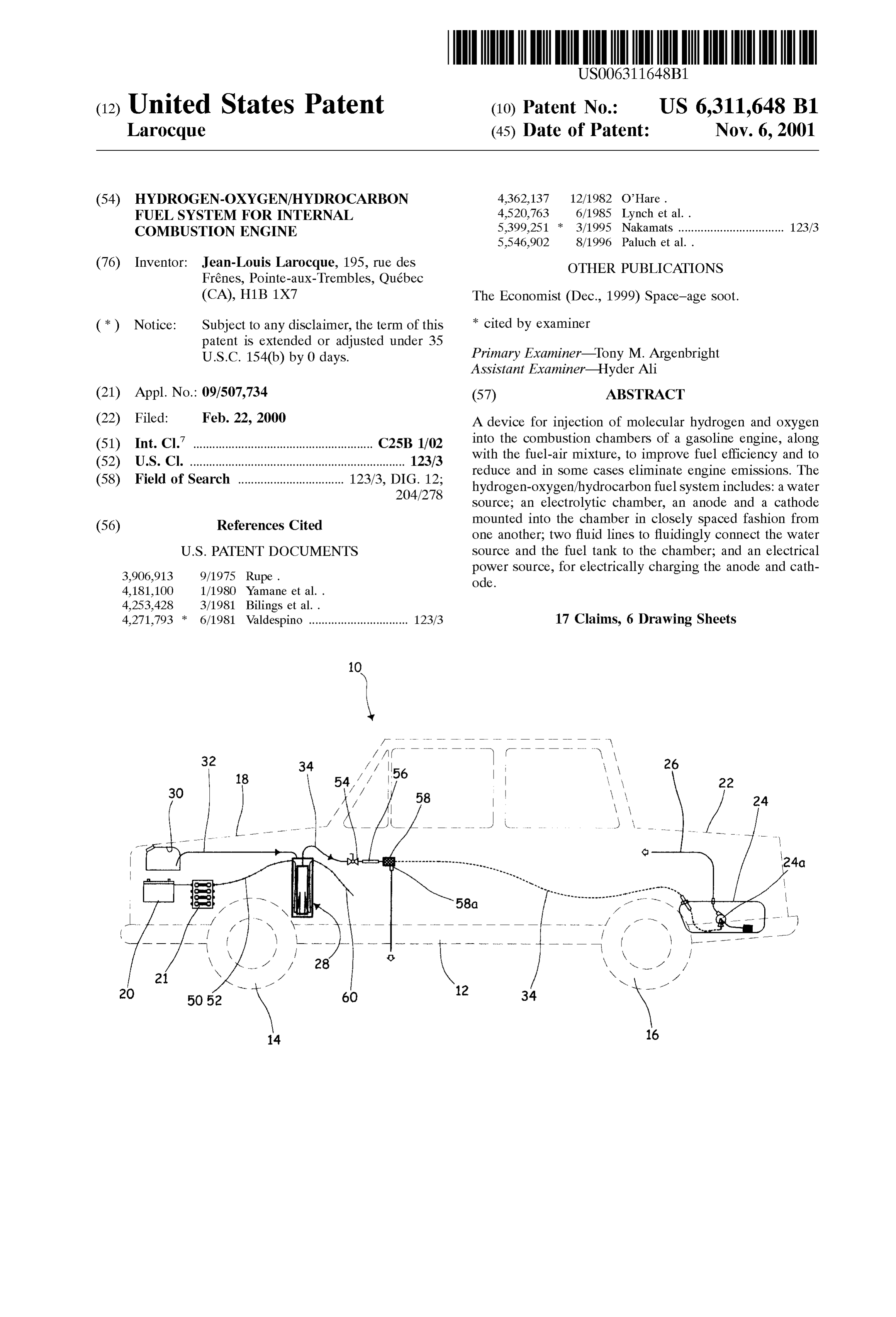
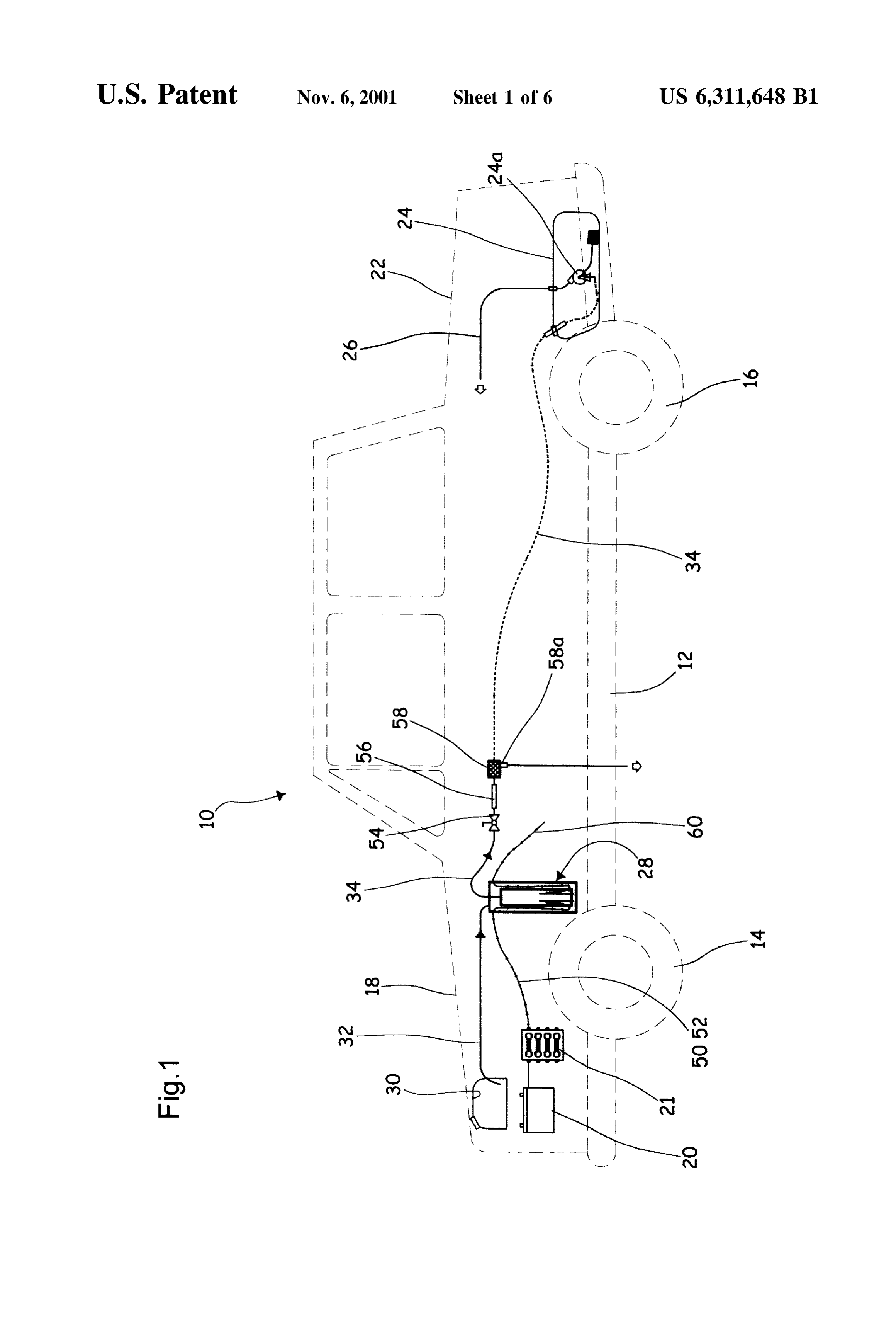
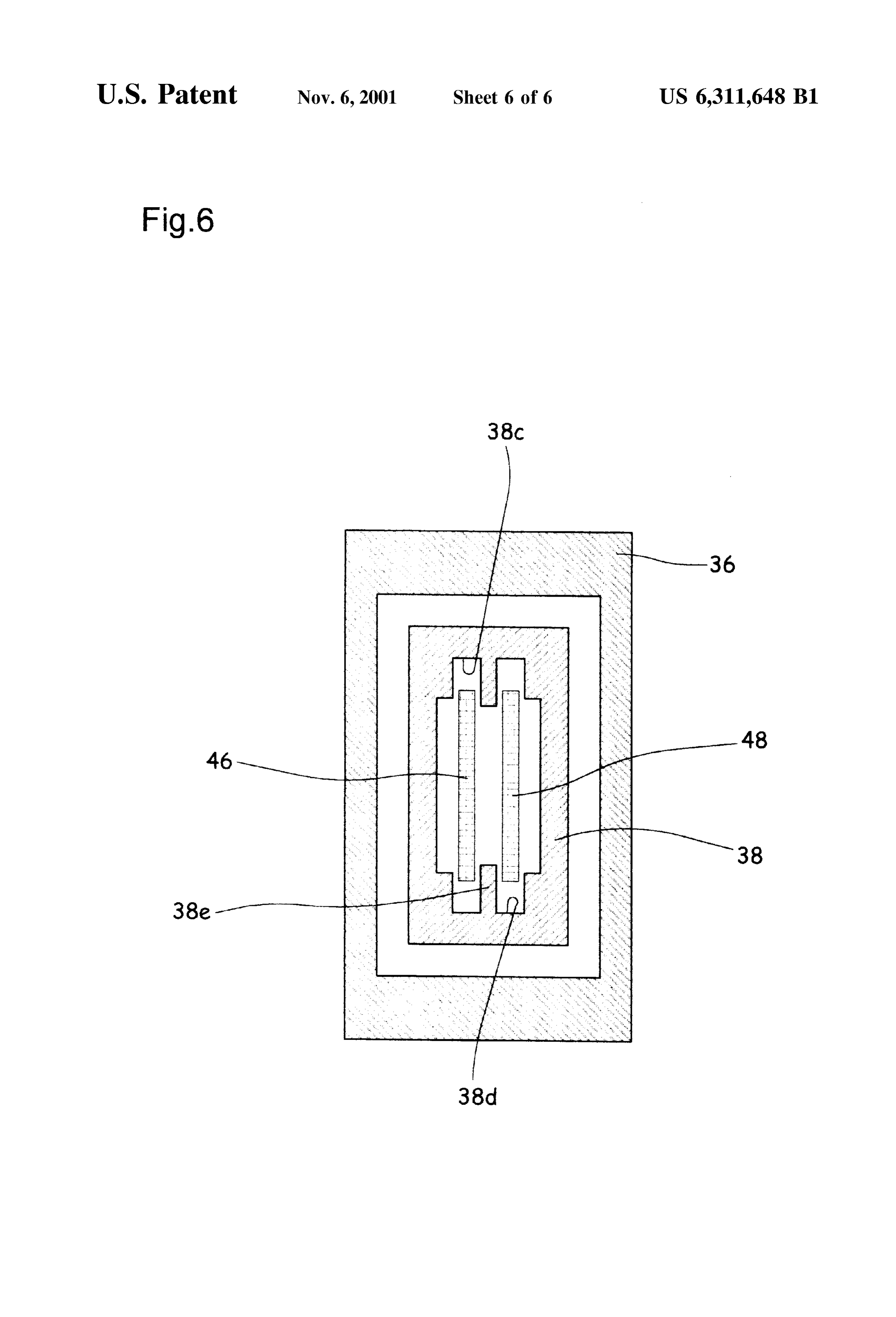
FIG. 1 is a side elevational view of an automobile, As best shown in FIGS. 4 and 6, inner housing 38 further Schematically illustrated in phantom lines, and fitted with includes a pair of lengthwise peripheral grooves 38C, 38D. the hydrogen-oxygen injecting device of the invention A pair of first and Second anode and cathode quadrangular shown in full lines; flat panels 46, 48, are fitted edgewisely inside respective FIG. 2 is an enlarged perspective view of the electrolytic grooves 38C, 38D, within inner housing 38, in spaced chamber used as a component of the hydrogen-oxygen parallel fashion relative to one another, and on opposite sides injecting device; of the peripheral inner rail 38E formed between the two FIG. 3 is an exploded view of the hydrogen-oxygen Spacer member grooves 38C and 38D. Hence, rail 38E constitutes an upright injecting device electrolytic chamber; 35 for maintaining panels 46, 48, positively spaced from one another. Preferably, the thickness of inner
FIG. 4 is a view similar to FIG. 2, but partly broken for rail 38E, and thus the distance between the two anode and improved clarity of the view of the electrolytic chamber cathode panels 46, 48, range Sbetween approximately 2 and elements, 4 millimeters (mm), and preferably about 3 mm. Panels 46, FIG. 5 is a vertical sectional view of the electrolytic 40 48, have a length for example half that of inner housing 38, chamber, at an enlarged Scale relative to that of FIG. 2.; and and a width slightly smaller than the width of the inner FIG. 6 is a cross-sectional view taken along line 6-6 of hollow of inner housing 38. Each panel 46, 48, is electrically FIG. 5. coupled to the battery 20 of automobile 10, via insulated electrical lines 50, 52, respectively. A fuse relay system 21
DETAILED DESCRIPTION OF THE is mounted to lines 50, 52, intermediate battery 20 and the
electrolytic chamber 28, to prevent the anode and cathode
INVENTION bars from receiving electric current when the motor engine The automobile illustrated in FIG. 1 as 10 conventionally is not running.
includes a chassis 12 carried over ground by a first pair of The preferred material for anode 46 is graphite and front axle wheels 14 and by a second pair of rear axle wheels 50 cathode 48 is brass. However, other Suitable materials are 16. Under the front hood 18 is found the motor engine, not not excluded from the Scope of the present invention, including:
shown, and under the rear trunk 22 is found the fuel tank 24.
The fuel tank 24 is fluidingly connected to the motor engine a) stainless steel-but durability is short; (not illustrated) via a flexible fuel line 26. b) silver-however their durability is then shorter; Accordingly with the invention, there is provided under 55 c) copper.
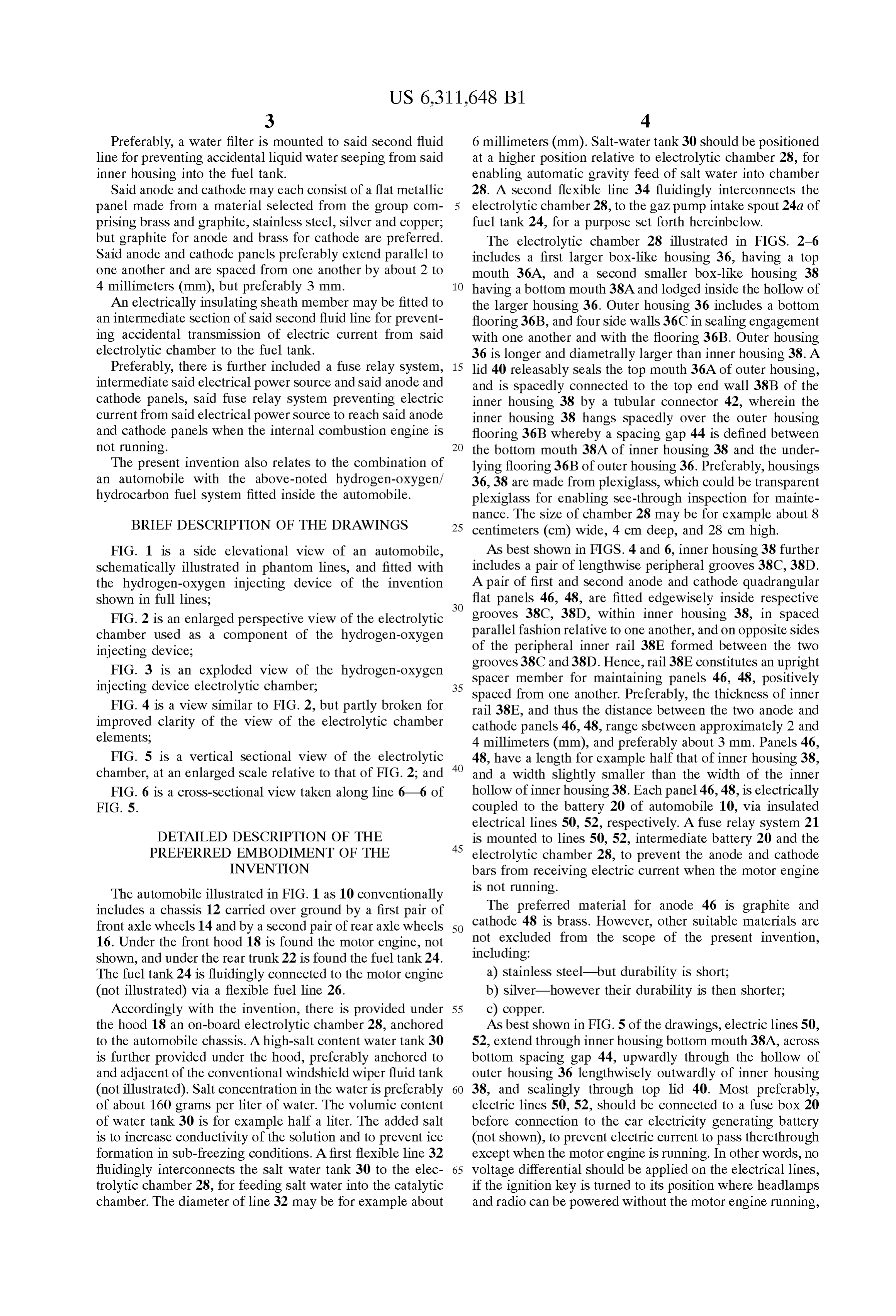
the hood 18 an on-board electrolytic chamber 28, anchored As best shown in FIG. 5 of the drawings, electric lines 50, to the automobile chassis. A high-salt content water tank 30 52, extend through inner housing bottom mouth 38A, across is further provided under the hood, preferably anchored to bottom spacing gap 44, upwardly through the hollow of and adjacent of the conventional windshield wiper fluid tank outer housing 36 lengthwisely outwardly of inner housing (not illustrated). Salt concentration in the water is preferably 60 38, and sealingly through top lid 40. Most preferably, of about 160 grams per liter of water. The volumic content electric lines 50, 52, should be connected to a fuse box 20 of water tank 30 is for example half a liter. The added salt before connection to the car electricity generating battery is to increase conductivity of the Solution and to prevent ice (not shown), to prevent electric current to pass therethrough formation in sub-freezing conditions. A first flexible line 32 except when the motor engine is running. In other words, no fluidingly interconnects the salt water tank 30 to the elec 65 Voltage differential should be applied on the electrical lines, trolytic chamber 28, for feeding salt water into the catalytic if the ignition key is turned to its position where headlamps chamber. The diameter of line 32 may be for example about and radio can be powered without the motor engine running,
Page 10
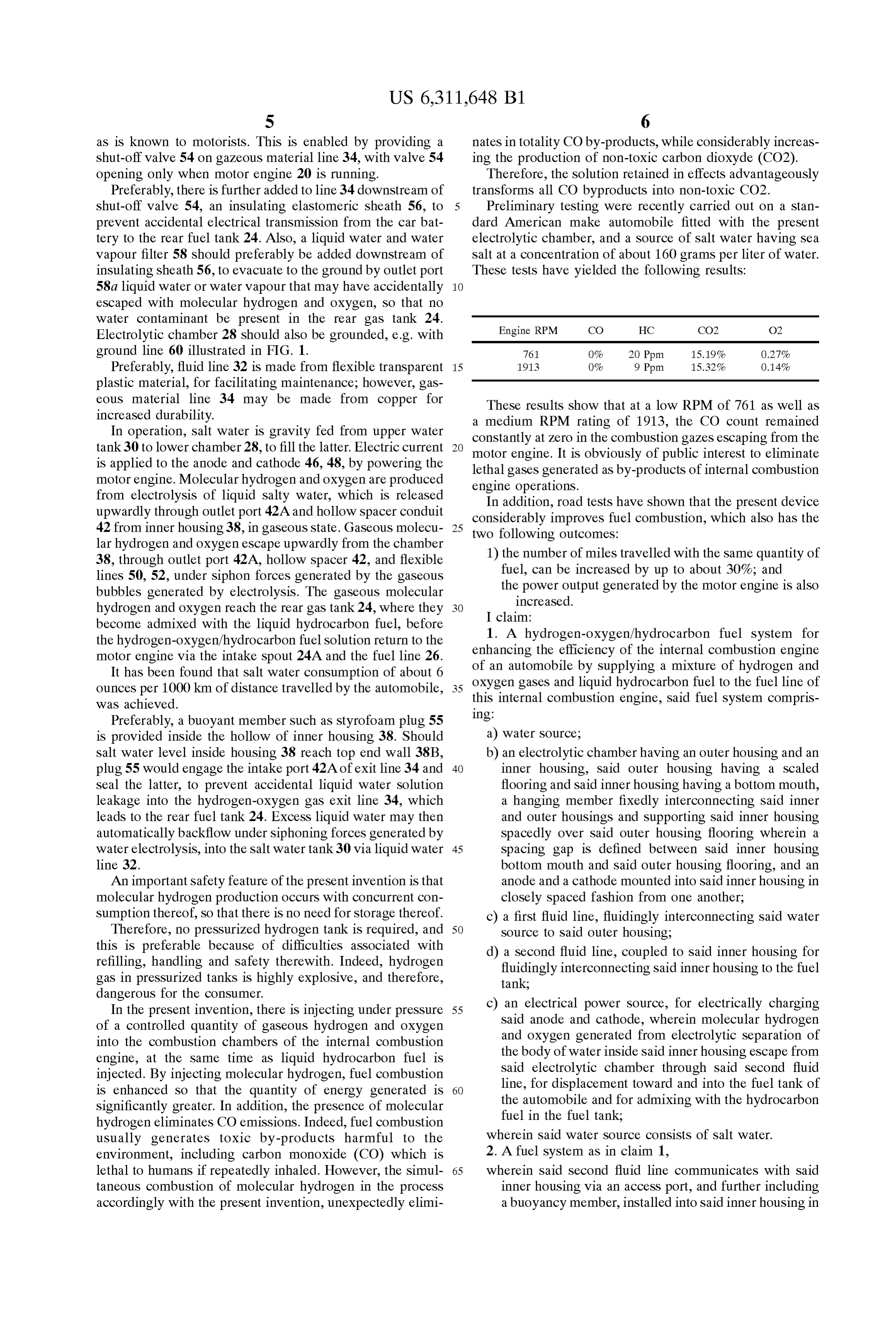
S 6 as is known to motorists. This is enabled by providing a nates in totality CO by-products, while considerably increas shut-off valve 54 on gazeous material line 34, with valve 54 ing the production of non-toxic carbon dioxyde (CO2). opening only when motor engine 20 is running. Therefore, the Solution retained in effects advantageously Preferably, there is further added to line 34 downstream of transforms all CO byproducts into non-toxic CO2. shut-off valve 54, an insulating elastomeric sheath 56, to Preliminary testing were recently carried out on a Stan prevent accidental electrical transmission from the car bat dard American make automobile fitted with the present tery to the rear fuel tank 24. Also, a liquid water and water electrolytic chamber, and a Source of Salt water having Sea vapour filter 58 should preferably be added downstream of Salt at a concentration of about 160 grams per liter of water. insulating Sheath 56, to evacuate to the ground by outlet port These tests have yielded the following results: 58a liquid water or water vapour that may have accidentally escaped with molecular hydrogen and oxygen, So that no water contaminant be present in the rear gas tank 24. Engine RPM CO HC CO2 O2 Electrolytic chamber 28 should also be grounded, e.g. with ground line 60 illustrated in FIG. 1. 761 O% 20 Ppm 15.19% O.27% Preferably, fluid line 32 is made from flexible transparent 15 1913 O% 9 Ppm 15.32% O.14% plastic material, for facilitating maintenance; however, gas eous material line 34 may be made from copper for These results show that at a low RPM of 761 as well as increased durability.
In operation, Salt water is gravity fed from upper water constantly atRPM a medium rating of 1913, the CO count remained
Zero in the combustion gazes escaping from the tank 30 to lower chamber 28, to fill the latter. Electric current is applied to the anode and cathode 46, 48, by powering the motor lethal engine. It is obviously of public interest to eliminate gases generated as by-products of internal combustion motor engine. Molecular hydrogen and oxygen are produced engine operations.
from electrolysis of liquid Salty water, which is released In addition, road tests have shown that the present device upwardly through outlet port 42A and hollow Spacer conduit considerably improves fuel combustion, which also has the 42 from inner housing 38, in gaseous State. Gaseous molecu 25 two following outcomes:
lar hydrogen and oxygen escape upwardly from the chamber 38, through outlet port 42A, hollow spacer 42, and flexible 1) the number of miles travelled with the same quantity of lines 50, 52, under Siphon forces generated by the gaseous fuel, can be increased by up to about 30%; and bubbles generated by electrolysis. The gaseous molecular the power output generated by the motor engine is also increased.
hydrogen and oxygen reach the rear gas tank 24, where they I claim:
become admixed with the liquid hydrocarbon fuel, before 1. A hydrogen-oxygen/hydrocarbon fuel System for the hydrogen-oxygen/hydrocarbon fuel Solution return to the motor engine via the intake spout 24A and the fuel line 26. enhancing the efficiency of the internal combustion engine It has been found that salt water consumption of about 6 oxygen gases and by of an automobile Supplying a mixture of hydrogen and ounces per 1000 km of distance travelled by the automobile, this internal combustion hydrocarbon
engine, Said fuel to the fuel line of fuel System compris was achieved.
Preferably, a buoyant member such as styrofoam plug 55 ing:
is provided inside the hollow of inner housing 38. Should a) water Source;
salt water level inside housing 38 reach top end wall 38B, b) an electrolytic chamber having an outer housing and an plug 55 would engage the intake port 42A of exit line 34 and 40 inner housing, Said outer housing having a Scaled Seal the latter, to prevent accidental liquid water Solution flooring and Said inner housing having a bottom mouth, leakage into the hydrogen-oxygen gas exit line 34, which a hanging member fixedly interconnecting Said inner leads to the rear fuel tank 24. ExceSS liquid water may then and Outer housings and Supporting Said inner housing automatically backflow under Siphoning forces generated by Spacedly over Said outer housing flooring wherein a water electrolysis, into the salt water tank 30 via liquid water 45 spacing gap is defined between Said inner housing line 32. bottom mouth and Said outer housing flooring, and an An important Safety feature of the present invention is that anode and a cathode mounted into Said inner housing in molecular hydrogen production occurs with concurrent con closely spaced fashion from one another; Sumption thereof, So that there is no need for Storage thereof. c) a first fluid line, fluidingly interconnecting said water Therefore, no pressurized hydrogen tank is required, and 50 Source to Said outer housing, this is preferable because of difficulties associated with d) a Second fluid line, coupled to said inner housing for refilling, handling and Safety there with. Indeed, hydrogen fluidingly interconnecting Said inner housing to the fuel gas in preSSurized tanks is highly explosive, and therefore, tank, dangerous for the consumer.
In the present invention, there is injecting under pressure 55 c) an electrical power Source, for electrically charging of a controlled quantity of gaseous hydrogen and oxygen Said anode and cathode, wherein molecular hydrogen into the combustion chambers of the internal combustion and oxygen generated from electrolytic Separation of engine, at the same time as liquid hydrocarbon fuel is the body of water inside Said inner housing escape from injected. By injecting molecular hydrogen, fuel combustion Said electrolytic chamber through said Second fluid is enhanced So that the quantity of energy generated is 60 line, for displacement toward and into the fuel tank of Significantly greater. In addition, the presence of molecular the automobile and for admixing with the hydrocarbon hydrogen eliminates CO emissions. Indeed, fuel combustion fuel in the fuel tank;
usually generates toxic by-products harmful to the wherein Said water Source consists of Salt water. environment, including carbon monoxide (CO) which is 2. A fuel System as in claim 1, lethal to humans if repeatedly inhaled. However, the simul 65 wherein Said Second fluid line communicates with Said taneous combustion of molecular hydrogen in the proceSS inner housing via an acceSS port, and further including accordingly with the present invention, unexpectedly elimi a buoyancy member, installed into Said inner housing in
Page 11
register with Said access port for Sealing the latter upon d) a Second fluid line, coupled to said inner housing for Said inner housing becoming completely filled to fluidingly interconnecting Said inner housing to the fuel capacity with water. tank, 3. A fuel System as in claim 1, e) an electrical power Source, for electrically charging wherein Said water Source is positioned higher relative to Said anode and cathode, wherein molecular hydrogen Said electrolytic chamber, whereby said water is gravity and oxygen generated from electrolytic Separation of fed to said electrolytic chamber. the body of water inside Said inner housing escape from 4. A fuel System as in claim 1, Said electrolytic chamber through said Second fluid further including a water filter, mounted to Said Second line, for displacement toward and into the fuel tank of fluid line for preventing accidental liquid water Seeping the automobile and for admixing with the hydrocarbon from Said inner housing into the fuel tank. fuel in the fuel tank;
5. A fuel system as in claim 1, wherein Said Second fluid line communicates with Said wherein Said anode and cathode each consists of a flat inner housing via an acceSS port, and further including metallic panel made from a material Selected from the 15 a buoyancy member, installed into Said inner housing in group consisting of StainleSS Steel, Silver, copper, brass register with Said acceSS port for Sealing the latter upon and graphite. Said inner housing becoming completely filled to 6. A fuel system as in claim 5, capacity with water.
wherein the material of Said anode is graphite and for 13. A hydrogen-oxygen/hydrocarbon fuel System for cathode is brass.
enhancing the efficiency of an internal combustion engine by 7. A fuel system as in claim 5, Supplying a mixture of hydrogen and oxygen gases and wherein Said anode and cathode panels extend parallel to liquid hydrocarbon fuel to the fuel line of this internal one another and are spaced from one another by about combustion engine, Said fuel System comprising: 2 to 4 millimeters.
a) a water Source;
wherein Said anode and cathode panels are spaced from b) an electrolytic member defining a main liquid chamber having a gas bell therein, Said water chamber and gas one another by about 3 millimeters. bell being in liquid communication with one another 9. A fuel system as in claim 8, under communicating vessels principle; wherein Said water Source consists of Salt water of a concentration of about 160 grams per liter of water, and c) an anode bar and a cathode bar mounted into Said gas Said Salt water Source is positioned higher than Said bell in closely spaced fashion from one another; electrolytic chamber, whereby Said Salt water is gravity a first fluid line, fluidingly interconnecting Said water fed to said electrolytic chamber. Source to said main liquid chamber; 10. A fuel system as in claim 5, d) a second fluid line, coupled to said gas bell for further including an electrically insulating sheath 35 fluidingly interconnecting Said gas bell to the fuel line;
and member, fitted to an intermediate Section of Said Second fluid line for preventing accidental transmission of e) an electrical power Source, for electrically charging electric current from Said electrolytic chamber to the Said anode bar and Said cathode bar, fuel tank. 40 wherein molecular hydrogen and oxygen generated front 11. A fuel system as in claim 5, electrolytic Separation of the body of water inside Said further including a fuse relay System, intermediate Said gas bell escape in gaseous State from Said gas bell electrical power Source and Said anode and cathode through Said Second fluid line, for displacement toward panels, Said fuse relay System preventing electric cur and into the fuel line and for admixing with the rent from Said electrical power Source to reach Said 45 hydrocarbon fuel; wherein Said water Source consists of anode and cathode panels when the internal combustion Salt water.
engine is not running. 14. A fuel system as in claim 13, 12. A hydrogen-oxygen/hydrocarbon fuel System for further including a water filter, mounted to Said Second enhancing the efficiency of the internal combustion engine fluid line for preventing accidental liquid water Seeping of an automobile by Supplying a mixture of hydrogen and 50 from Said gas bell.
oxygen gases and liquid hydrocarbon fuel to the fuel line of 15. A fuel system as in claim 13, this internal combustion engine, Said fuel System compris wherein Said anode bar and cathode bar each consists of ing: a flat metallic panel made from a material Selected from a) water Source; the group consisting of Stainless Steel, Silver, copper, b) an electrolytic chamber having an outer housing and an 55 brass and graphite.
inner housing, Said outer housing having a Sealed 16. A fuel system as in claim 13, flooring and Said inner housing having a bottom mouth, wherein Said anode bar and cathode bar extend parallel to a hanging member fixedly interconnecting Said inner one another and are spaced from one another by about and Outer housings and Supporting Said inner housing 2 to 4 millimeters.
Spacedly over Said outer housing flooring wherein a 60 17. A fuel system as in claim 13, spacing gap is defined between Said inner housing wherein Said Salt water Source is at a concentration bottom mouth and Said outer housing flooring, and an between about 100 and 200 grams of salt per liter of anode and a cathode mounted into Said inner housing in water, and Said anode and cathode bars are made front closely spaced fashion from one another; graphite and brass.
c) a first fluid line, fluidingly interconnecting said water 65
Source to Said outer housing, k k k k k
Provenance
- Collection
- Cited prior art
- Original PDF
- patentimages.storage.googleapis.com →
- Filed
- 2000-02-22
- Pages
- 11
- Method
- pdftotext (the PDF's own text layer) + pdftoppm 300dpi page scans
- Source
- Google Patents bibliographic record
- Granted
- 2001-11-06
- Inventors
- Jean-Louis Larocque
- Transcribed from
- patentimages.storage.googleapis.com →