patent · US3679568
Cell construction
25 July 1972
Page 1
Drawing sheet — no readable text.
Page 2
Drawing sheet — no readable text.
Page 3
Drawing sheet — no readable text.
Page 4
Drawing sheet — no readable text.
Page 5
Drawing sheet — no readable text.
Page 6
Drawing sheet — no readable text.
Page 7
Drawing sheet — no readable text.
Page 8
Drawing sheet — no readable text.
Page 9
United States Patent Office Patented July 25, 1972
or tank. A typical conventional bipolar electrolytic cell 3,679,568 usually consists of a housing in the form of a box having CELL CONSTRUCTION an open top, in which are positioned a large number of Gothe O. Westerlund, Vancouver, British Columbia, Can Spaced-apart, parallel electrodes, usually of graphite. ada, assignor to Chemech Engineering Ltd., Vancouver, 5 Electrical connections are made to two or more, but not British Columbia, Canada
Filed Sept. 17, 1968, Ser. No. 760,209 all, of the electrodes for supplying electrical energy to Claims priority, appliciganada, Oct. 13, 1967, the cell. Electrodes are, in effect, connected in series elec s trically through the electrolyte in the cell. At the top and Int. C. B.01k 3/00 E01c 2/04 bottom of the housing on both sides thereof, there are U.S. C. 204-242 84 Claims 0. tubes leading into the housing. A sufficient number of these tubes, which constitute inlet and outlet tubes, are provided to communicate with each one of the spaces be
ABSTRACT OF THE DESCLOSURE tween two adjacent electrodes. Every two adjacent elec An improved electrolytic cell of enhanced durability and 5 trodes, and the space therebetween, constitutes a unit cell. The housing is supported above the floor of the con ease of construction is provided which includes a novel tainer or tank, the latter being filled with electrolyte. cover member, with or without novel cell wall structure The electrolyte enters each unit cell through the lower and/or novel internal structure of the electrolytic cell tank. The cover is characterized by three members which tubes (these being below the level of the electrolyte in the sealingly engage with the upper surface of the electrolytic 20 tank), solution is electrolyzed in the unit cells and the electrolyzed is discharged to the tank by the upper tubes, the cell tank to provide an inlet manifold and a separate and tank constituting a common reservoir for all cell units. distinct outlet manifold, with the inner exposed surfaces In many cases, circulation of the electrolyte from the of the cover being resistant to the chemicals within the tank to the unit cells and back to the tank is obtained electrolytic cell tank. The cell wall construction is char without the use of pumps or other similar positive dis acterized by a "sandwich' of an outer shell, an inner placement circulating devices. However, a pump may be lining, formed of a single appropriately sized lining sheet 25 employed if desired. In cases where the common reser or an array of lining sheets separated by, but joined by voir tank is positioned remote from the electrolytic cell means of specified sealing members, and a mortar bonded instead of being positioned with the electrolytic cell there to the shell and anchored to the lining. within, some form of pumping arrangement is required. 30 While electrolytic cells of the aforementioned type with their associated tanks are in wide-spread use, their com
The internal structure of the electrolytic cell tank in mercial utilization is subject to a number of disadvan cludes a plurality of longitudinally extending spaced apart tages. Thus, as aforementioned, inlet and outlet tubes are bipolar electrodes and two lateral, longitudinally extend employed because of the necessity to minimize current ing monopolar electrodes, the space between adjacent 35 leakage between adjacent unit cells. However, the use of electrodes constituting an electrolytic cell unit, inlet means tubes creates problems with respect to obtaining good for admitting liquor into each of the electrolytic cell units, circulation of electrolyte from and to the electrolytic cell a top header providing an outlet for liquor from each of when natural circulation is relied upon, and this naturally the electrolytic cell units and one of the sealing men has an effect on efficiency.
bers of the cover being sealingly engaged with the top 40 Furthermore, notwithstanding the use of such tubes, header. current leakage from unit cells, such as those described This invention relates to novel and improved construc and now in use, does occur, and in many cases is a signi tion of the walls and cover of electrolytic cells. The cells ficant factor in decreasing the efficiency of operation since with which the present invention is particularly concerned the tubes must be reasonably large to promote adequate are those cells which are suitable for the production of 45 circulation. The potential between an electrode in the metal chlorates from aqueous solutions of metal chlorides electrolytic cell in the tank may be quite high, i.e. the end and especially for the production of alkali metal chlorates electrodes of the cell may be at --60 and -60 volts from alkali metal chloride brines. Other cells with which respectively, while the tank is at zero volts, and this dif the present invention is also concerned are those cells ference in potential promotes current leakage, the degree which are suitable for the production of perchlorates from of current leakage being greater as the difference in sodium chlorate solutions, for the production of gaseous potential increases. With conventional electrolytic cells chlorine from hydrochloric acid solutions, and (if the cell of this type, the maximum voltage drop across the elec is modified to include a diaphragm therein) for the pro trolytic cell which normally has been employed is about duction of gaseous chlorine and gaseous hydrogen. This 120 volts.
invention relates more specifically to an improved electro 55 Other bipolar electrolytic cells which have been de lytic cell structure, namely a novel and improved particu signed to avoid many of the difficulties inherent in mono lar construction of the cell walls as well as to a method polar cells have brought about several different major for constructing the cell walls. This invention also relates problems. Such bipolar cells were usually designed to to a novel closure member for such cells. This invention operate with a gas phase above the level of the liquor and relates further to novel components and combinations of 60 below the cell cover. The electrical connections to the components within the improved cell. graphite electrode were situated in this gas phase and ac Known electrolytic cells for the production of metal cordingly, the danger of sparks occurring with the chlorates from aqueous solutions of metal chlorides us resultant explosion hazard was always present. ing consumable carbon electrodes have certain disadvan 65 It has also been common practice to construct elec tages. Monopolar cells inherently have many power con trolytic cell tanks and cell boxes for use in the electro nections and electrolyte branches, high electrode stub lytic production of these products of concrete, slate, steel losses, high voltage drop and high power losses. Further (in cases where the steel becomes a part of the cathode more, many units are required in commercial production in the cell box), and steel lined with ceramic or rubber. and much larger building spaces are required. Thus, according to conventional practice, the tank for Metal chlorates may also be produced electrolytically O the electrolytic cell may comprise bottom and side walls from aqueous solutions of metal chlorides by means of constructed of steel coated with a non-conductor, Such a bipolar electrolytic cell positioned in a large container as rubber or polymerized vinylidene chloride, and non
Page 10
conducting end walls which may be made of any cor in an electrolyte. They can also be welded, drilled, bolted rosion-resisting material having substantial strength and and readily cut. However, the use of such polymers as the rigidity, such as polyvinyl chloride, hard rubber or metal sole component in the structure of an electrolytic cell having a non-conducting coating, such as rubber, on the suffers the principal disadvantage that the cell so con interior faces. The bottom, sides and ends may be structed is not structurally rigid. fastened together to provide a totally-joined, leak-proof Similar problems have occurred in electrolytic dia chamber, which is open at the top. phragm cells of the alkali chlorine type. Thus, in indus A cell tank or cell box fabricated from concrete accord try today many operations are performed in the prepa ing to conventional practice produced a heavy and cum ration of the bottom assembly of a conventional dia bersome structure. Materials such as concrete, slate, or O phragm-type electrolytic cell, and especially for the pro steel are not considered to be flexible materials and this duction of the metallic parts located in the bottom there inhibits freedom in the design of the electrolytic cell of. Typically, the soft metallic material, usually lead, tanks and cell boxes. Because of the corrosive nature of utilized to convey current from the bus bar to the anode the electrolysis reaction, it was necessary to protect the of the cell, is normally covered with an epoxy-coal tar cell tank and protecting the cell tank lining by means of 5 composition for the alleged purpose of sealing the metal a tile lining has been suggested. However, it was found parts from the interior of the cell. Upon completion of that the tiles were either porous when installed or became such alleged sealing of the soft metal bottom, the cell porous during the course of operation of the tile. Fur is covered with a thick layer of mastic or organic sealant, thermore, the joints between the tiles were vulnerable to thus alleging to afford more protection for the metallic chemical attack. Finally, the tolerances in the dimensions 20 portions of the bottom of the cell from attack by the hot when the cell was constructed were relatively large. Thus, chlorinated brine during electrolysis of the alkali metal concrete and ceramic tile eventually tended to become chloride solutions.
electrically conductive after they had been immersed in Another method proposed for protecting the cell bot an electrolyte. Furthermore, concrete and ceramic tile toms was the provision of layers of mastic and layers of were unable to tolerate wide variations of the temperature 25 grout between the soft metal conductors in the bottom of the electrolyte because of the problems arising from of the cell and the interior of the cell. cracking. Finally, concrete and the cement which was It has further been proposed to provide a lining which used to hold the ceramic tiles in place contain constitu would reduce considerably the man-hours necessary for ents which leach out in the electrolyte, thereby con properly lining a cell bottom in a typical electrolytic taminating the electrolyte and forming deposits on the 30 diaphragm-type alkali chlorine cell. The lining proposed cathode electrodes. A similar type of problem arose when was one which allegedly would be extremely resistant slate was used, since slate contains constituents that will to the activity of hot chlorinated brines encountered dur leach out in the electrolyte. ing electrolysis of alkali metal solutions. Thus, it has In certain other cells of the bipolar type in which the been proposed that, by spraying the metallic portions of cell was provided with a lining of rubber, it had been 35 the bottom of an electrolytic alkali chlorine cell with an found that the rubber was likely to fail since rubber has organic sealant (i.e. a bituminous material), then affixing the distinct disadvantage of hardening with age and be to the sealant prior to its drying a sheet of inert fibrous coming brittle and cracking, thereby permitting the cor material, such as asbestos, paper, or cloth, and finally rosive electrolyte to attack the shell of the cell, particu coating the inert fibrous material with sealant, an effec larly in the cover. A failure of this type was likely to 40 tive lining was alleged to be presented to the hot chlo result in production losses due to partial or complete rinated brine solutions encountered in electrolytic cell shut-downs, and to high maintenance costs. operation.
Cell tanks and boxes fabricated of, or with liners There have been several previous additional attempts formed from, such materials have relatively short life be to produce other plastic cell liners. These attempts have cause of the corrosive environment in which they are 45 been substantially unsuccessful because of cracking, warp used in a relatively short time they must be replaced or ing, delamination, and other types of structural failures. repaired because of chemical attack by the electrolyte This lack of success has been particularly notable in during electrolysis. This is a most serious, but not the attempts to produce a seamless one-piece liner. only, disadvantage of cell tanks and boxes constructed There is continued interest in the production of such according to conventional practice of such materials. 50 liners because an acceptable plastic liner would have In order to overcome the disadvantages of cell tanks many substantial advantages, i.e. resistance to attack by and boxes constructed of such materials, the use of poly chemicals, low cost, ease of installation, maintenance and vinyl chloride has been suggested. It has indeed been repair, elimination of the layer which has been conven found that cell tanks and boxes constructed of polyvinyl tionally used as a liner material and elimination of other chloride and used, i.e. in the electrolytic production of 55 metallic or conductive members from electrolytic cells, sodium chlorate from sodium chloride brine, are charac thereby substantially eliminating stray current which de terized by improved corrosion resistance. Recently it has creases the efficiency of the electrolytic function of the been proposed that even better corrosion resistance and cells.
longer life for a cell tank or cell box could be obtained A proposal has been made to provide a cell liner if the cell were constructed of a grade of polyvinyl chlo 60 formed from a plastisol. According to such proposal, a ride that is free from both solvents and plasticizers for polyvinyl plastisol would be formed into a cell liner the polyvinyl chloride, and if the joints of the cell tank having appropriate configuration by a mold-coating and or cell box are welded using such polymer. curing process. The liner would be pre-heated to render it It has also been proposed that cell tanks and cell boxes sufficiently flexible so that it may be caused to assume be fabricated either from polyvinyl dichloride or poly 65 substantially the shape of the cell into which it was to vinyl difluoride. Polyvinyl dichloride and polyvinyl di be inserted. Upon cooling, the liner would be in substan fluoride are reputed to be resistant to chemical attack tially close contact with the wall of the cell and would from electrolytes of the types that are used in the elec allegedly conform with a great degree of accuracy to trolytic production of halogens, hypohalites, halites and the configuration thereof, as compared with conventional perhalites of the alkali metals. Such polymers are alleged liners. It has been suggested that unexpected superior re to be lighter materials, more easily repaired if physically 70 sults may be obtained if certain dimensions of the molded damaged and more readily pre-fabricated than the mate liner were the same as the corresponding dimensions of rials described hereinabove which have been used in the the cell, while certain other dimensions were either less past. Furthermore, such materials are alleged to remain than or greater than other corresponding dimensions of non-conducting electrically after having been immersed 75 the cell. In the case where a polyvinyl chloride plastisol
Page 11
was used to produce a substantially rectangular cell liner, other. It was though that current leakage could be kept the molded liner would be slightly undersized in width to a minimum even when adjacent unit cells were cas and depth, full-sized in length, and the end flanges thereof caded, which could be done by interconnecting the re would be slightly oversized. Such proposal was unfeasible action zones because the passages interconnecting the since the cell liner was generally inconvenient to produce. reaction zones were made quite small, thereby estab The conventional electrolytic cell may also be provided lishing the path of high electrical resistance. with a cover member which, according to conventional It is appreciated that when the bipolar electrolytic cell practice, may be bolted to the side walls by a plurality of has essentially no current leakage, voltages in excess of bolts which traverse a flange member welded to, or other 120 volts can be employed. This would be advantageous wise forming, an integral part of the side walls. Between O since rectifier costs and bus bar costs decrease with in the cover member and the flange member a rubber lining creasing voltage so that the cost of rectified current de and an asbestos gasket are usually provided, according creases when the voltage is increased. to conventional practice, to prevent leakage from inside An object, therefore, of one aspect of the present in of the cell. vention is to provide a means to lower the construction It is now appreciated that rubber-lined steel covers for 5 costs of an electrolytic cell.
such cells are not always satisfactory because of pores An object of another aspect of the present invention developed in the rubber lining. This results in both cur is to provide an electrolytic cell which is constructed in rent leakage and problems of corrosion. part from conventional-type tanks to take advantage of Applicant has previously proposed in his Canadian the reinforcement and safety characteristics of such tanks. Pat. No. 741,778, as well as in his pending Canadian ap 20 An object of yet another aspect of the present inven plication Ser. No. 928,684 filed Apr. 21, 1965 (United tion is to provide a particular construction technique for States application Ser. No. 543,261 filed Apr. 18, 1966, constructing such tank to close tolerances. now U.S. Pat. No. 3,463,722) to provide an all-plastic An object of another aspect of the present invention is cell cover, for example, a fiberglass-reinforced polyester the provision of an electrolytic cell in which a particular cover. While such a cover is feasible, the designs 25 outer shell, inner lining and intermediate bonding material heretofore have been rather complex. Such complex is provided.
designs offer construction problems, as Well as prob An object of yet another aspect of the present inven lems in selecting suitable materials chemically re tion is the provision of a novel system of providing the sistant to the liquor. Polyester resins which are now com 30 lining for the electrolytic cell. mercially available have been found to be not sufficiently An object of yet another aspect of the present inven chemically resistant to attack, and a lining adhered to tion is the provision of a novel means of anchoring the such polyester resins, e.g. a polyvinyl chloride lining, lining to the intermediate bonding material. would, therefore, have to be employed. However, even An object of still another broad aspect of the present such a lining may tend to give maintenance problems be invention is the provision of a substantially electrolyte cause of the uncertain means of adhering the lining to the corrosion-resistant cover for an electrolytic cell. plastic cover itself. Alternatively, the cover could be An object of another aspect of the present invention is fabricated of polyvinyl chloride sheeting. However, ap the provision of such a cover in which problems of thermal plicant has found that where fabrication is required in expansion and/or contraction are minimized. volving thermal and/or solvent-welding, the maintenance 40 is An object of yet another aspect of the present invention the provision of such a cover which is formed in problems are considerable, particularly when one has to segments in which joints are provided for lengthwise consider thermal expansion and/or contraction problems thermal dimensional changes.
which are inherent in such construction.
Attempts have also been made to solve the problem of theAnprovision object of another aspect of the present invention is of a special clamping means for clamping current leakage within the cell. A bipolar electrolytic cell has been proposed that included a housing adapted to 45 theAnsections of the novel cover together. object of yet another aspect of the present invention receive and contain electrolyte. At least three electrodes were positioned in the housing in spaced apart relation iscover the provision of novel clamping means for securing the to an upper structure of the electrolytic cell.
ship with respect to each other, each set of two adjacent An object of still another aspect of the present inven electrodes and the space therebetween constituting a unit cell for the electrolysis of an electrolyte occupying the 50 tion is the provision of means for minimizing current losses within the cell.
space between the two adjacent electrodes. Each of the Thus, by a main aspect of the present invention, an electrodes in a set of two adjacent electrodes were dis posed to face each other. Means were provided defining electrolytic
cell is provided comprising, in combination, electrolytic cell tank and a cover, the cover comprising:
a plurality of individual chambers, each one of these individual chambers being connected in liquor flow re 55 three spaced apart sealing members sealingly engaged to an upper surface of the electrolytic cell tank, the sealing lationship with a different one of the unit cells for passage members thereby cooperating with a structure on the of electrolyte into respective ones of the unit cells from upper surface of the electrolytic cell tank to provide a the individual chambers connected thereto, and out of separate and distinct inlet manifold for the inlet of respective ones of the unit cells into the individual chambers also connected thereto. The total volume defined 60 liquor to the electrolytic cell tank and a separate and by the individual chambers plus that of the spaces be distinct outlet manifold for the outlet of liquor and gaseous tween the adjacent electrodes constituted substantially products of electrolysis from the electrolytic cell tank, the only volume provided for chemical reactions as the the inner exposed surfaces of the cover including a ma result of electrolysis of the electrolyte to take place in terial selected from the group consisting of rubber and the electrolyte. Since there need not be any physical 65 are plastics; whereby, on removal of the cover, the manifolds member spearating the electrolysis zone of the unit cell simultaneously removed, thereby leaving the electro from the individual reaction zone, it was though that lytic cell open for inspection and/or repair. circulation could be considerably improved and could By another aspect of this invention, the cover is as provide a greater flow of electrolyte over the electrode described above, and the electrolytic cell tank includes a faces, which would allegedly result in improved current 70 plurality of longitudinally extending spaced apart bipolar efficiency. electrodes and two lateral, longitudinally extending mono It was also thought that the electrolytic cell so con polar electrodes, the space between adjacent electrodes structed would allegedly have virtually no current leakage constituting an electrolytic cell unit; inlet means for ad between adjacent unit cells or between adjacent reaction mitting liquor into each of the electrolytic cell units; a zones because they were essentially isolated from each 75 top header providing an outlet for liquor from each of
Page 12
the electrolytic cell units; and further wherein one of the The cell of another aspect of the present invention in sealing members of the cover is sealingly engaged with cludes a plastic sheeting as a lining for the cell. This the top header. protects the intermediate bonding mortar material against By still another aspect of this invention, the cover is as chemical attack and also protects the rubber lining of con described above, and the cell wall construction of the ventional cells. The use of plastic sheeting makes it possi electrolytic cell tank comprises: (a) an outer structurally ble to employ, as a construction member, a unit which is rigid shell; (b) an inner lining of a substantially chemically - easily installed. This enables the fabrication of the elec inert plastic material disposed at accurately predetermined trolytic tank to almost exact dimensions and yet also to locations within the shell; and (c) a mortar filler bonded provide a surface which is resistant to the corrosive effects to the shell and anchored to the lining; wherein accurate O of the liquor within the cell.
tolerances for the dimensions of the electrolytic cell are By this particular construction, the invention also pro provided in order to minimize current leakage within the vides for a lower tolerance requirement for the shell or cell, whether or not the electrolytic cell tank has the supporting structure. The shell or supporting structure may specific structure described above. be a rubber or other lined steel tank, or may be a fiber In one embodiment of the aspects of the invention 5 glass-reinforced polyester tank. If the fiberglass-reinforced noted above, the cover includes a pair of elevated Sec polyester tank is used, it would not be necessary to pro tions separated by a depressed section, sealing members at vide a rubberlining. However, because of safety considera the inner surface of the edges of the elevated sections tions due to the possibility of cracking, applicant prefers and at the inner surface of the depressed section engaging to use a rubber-lined steel tank. The lower tolerance re the upper surface of the electrolytic cell tank, thereby 20 quirement is an important consideration since applicant to provide the separate and distinct manifolds. has found that the cost will be extremely high if a tank In a second embodiment of the aspects of the invention has to be built to such close tolerance that the desired noted above, the cover includes (a) the depressed sec lower current leakages within the cell itself are main tion including a central longitudinally extending de tained. The accuracy to maintain such lower current leak pressed trough portion; (b) the pair of elevated sections 25 ages is provided, according to aspects of this invention, including a pair of lateral longitudinally extending raised by the cell lining location.
lips co-extensive with the side walls of the trough por This invention also uses, as a construction member, a tion; and wherein the sealing members include: (c) sealing unit which contains the intermediate bonding mortar until members sealingly engaged between the inner lower the mortar is set. In other words, the mortar is poured most surface of the trough portion and the upper surface 30 into the designated space to fill the voids, as well as to per of an auxiliary cover element disposed within the electro mit quicker construction.
lytic cell tank; and (d) sealing members sealingly en The present invention also provides special seals in gaged between the inner surfaces of the lips and the upper serted in the plastic sheeting units which are used in form surface of opposed walls of the electrolytic cell tank. ing the lining. These seals also provide expansion joints In a third embodiment of the aspects of the invention 35 for the plastic sheeting and for the intermediate mortar as noted above, the cover extends between side walls bonding material. The plastic sheeting is, for practical of the electrolytic cell tank and further is provided as a purposes, considered to be chemically inert to the electro plurality of longitudinally abutting and secured segments, lyte containing in the cell.
particularly where the individual segments of the plurality The sheeting units are preferably installed using jigs to of longitudinally abutting and secured segments are pro 40 set them at the precise exact positions, and mortar is en vided with upstanding marginal flanges, where a con ployed as a filler between the plastic sheeting and the pressible material is disposed between flanges of adjacent supporting structure. Anchor means of particular design segments, and where a clamp is provided for clampingly which will be described in detail hereinafter are also securing the adjacent flanges together, or where the indi provided for securing the sheeting to the mortar and the vidual segments of the plurality of longitudinally abutting 45 mortar to the rubber lining and/or other tank walls. and secured segments are provided with means for securing A novel design of cover for an electrolytic cell has also a clamp to each of the segments, where a flexible com been provided which employs a curvature to provide a pressible material is disposed between lateral edges of dividing wall between the inlet and outlet headers. This the adjacent segments and where a coupling nut is pro cover also provides a positive seal at the upper structure vided for securing the clamps together. of the electrolytic cell, namely at the top profile headers In a fourth embodiment of the aspects of the inven 50 of the electrolytic, by employing a rubber profile between tion as noted above, the cover includes a flat plate section, the bottom surface of the curved cover and the upper sealing members at the edges thereof sealingly engaging surface of the top profile headers. The electrolytic cell tank upward extensions of mutually opposed walls of the end wall is provided with a top flange which has the same electrolytic cell tank, and a longitudinally extending plate 55 contour as the plastic sheeting cover and extends to an disposed between the bottom surface of the flat plate sec elevation close to the top profiles. Thus, the problem of tion and the upper surface of an auxiliary cover element sealing the ends of the tank at the dividing wall is mini disposed within the electrolytic cell tank, thereby to pro mized. The curvature of the cover not only provides vide the separate and distinct manifold chambers, partic structural strength for both over and/or under-pressures, ularly where it includes sealing members sealingly en but also provides for thermal expansions and/or con gaged between the upper surface of the auxiliary cover 60 tractions.
element disposed within the electrolytic cell tank and The cross-section may be of any shape as long as it the lower marginal edge of the divider wall to provide for provides alongitudinally extending depressed trough and a thermal changes of size of the longitudinally extending pair of lateral longitudinally extending raised portions. plate; and sealing members sealingly engaged between the 65 Thus, in one embodiment, the cover may have the cross upper marginal edge of the divider wall and the lower section corresponding approximately to the graph of the surface of the cover in order to provide for thermal equation y=sine x, from ar?2 to 5ar/2 (i.e. it may be a changes of size of the longitudinally extending plate. sine curve).
By a preferred aspect of any of the above-referred to In a second embodiment of this aspect of this invention, aspects or embodiments of this invention, the outlet mani 70 the cross-section of the trough portion of the cover cor fold has a uniformly increasing cross-sectional area, rela responds approximately to the graph of the equation tive to the direction of outward flow of cell liquor. x2-4ay, i.e. it is in the shape of a parabola. By another aspect of the present invention, inlet pipes In a third, embodiment of this aspect of this invention, and/or outlet pipes are provided in the inlet and/or outlet the cross-section of the cover corresponds approximately manifolds respectively. 75 to the graph of the equation y=e.
Page 13
In a fourth embodiment of this aspect of this invention,cant artifically creates a length which is inside the cell the trough portion of the cover corresponds approximately and thus, due to the construction, takes very little space, to the graph of the equation y=loga. and is virtually maintenance-free with a minimum pressure In a fifth embodiment of this aspect of the present differential.
invention, the cross-section of the cover corresponds ap 5 The cell of various aspects of this invention is specifical proximately to the graph of the equation ly and expressly filled with the electrolyte. Operation of 8 the cell should be carried out at a high velocity throughout
so that the gaseous products of electrolysis are maintained in the electrolyte as finely divided bubbles. It is also desir i.e. it is in the shape of a cissoid. 0 able to provide for turbulent flow in the portion of the In a sixth embodiment of this aspect of this invention, cell between the upper profile headers and the cell cover. the cross-section of the cover corresponds approximately The high velocity is usually between about 2 and 100 ft./ to the graph of the equation sec. with a preferred rate being of the order of 10 ft./sec. The high velocity not only maintains the gaseous products 15 of the electrolysis reaction entrained in the electrolyte but also mixes the fresh electrolyte with the recirculating i.e. it is in the shape of a hyperbolic sine curve. electrolyte.
In a seventh embodiment of this aspect of this inven The plastic material which may be used for the sheeting tion, the cross-section of the cover corresponds approxi lining of the cell and also for the plastic cover includes mately to the equation 20 polyvinyl chloride, polyvinyl dichloride, polyvinyl difluo ex--ex ride, polyethyelne, polypropyene, and those known by the y=- registered trademarks of Penton (chlorinated polyether i.e. it is in the shape of a catenary. derived from 3,3-bis(chloromethyl)oxetane, a thermo Furthermore, as an alternative to the depressed section 25 plastic resin), Plexiglas (a thermoplastic poly(methyl methacryate)-type polymer available in sheet form) or elevated sections (or vertex-two apex) type cover design PerspeX a methyl methacrylate resin available in sheet of another aspect of this invention, applicant may employ form.
a rectangular cell tank extended above the top profile The mortar may be any chemically-resistant mortar, assembly to provide for an outlet and an inlet header. preferably with low shrinkage characteristics and good This would facilitate employing a flat plastic sheeting for 30 the cover. In order to solve the problems with respect bond to the rubber lining. Mortars may be made from to the dividing wall between the manifolds to prevent the cement known by the trademark of Ciment Fondu, a short circuiting of the liquor, it is necessary to provide for typical cement which contains 44% alumina, 40% lime, sealing against the top profile, as well as sealing against 10% silica, and 3.5% metallic iron with small amounts of the cover and the ends of the cell tank. The dividing wall 35 magnesia and ferric oxide or polyester resin mortars, such must also be removable in order to make it possible to as that known by the trademark of Hetron (one of a line install the graphite electrodes and the top profile headers. of polyester resins).
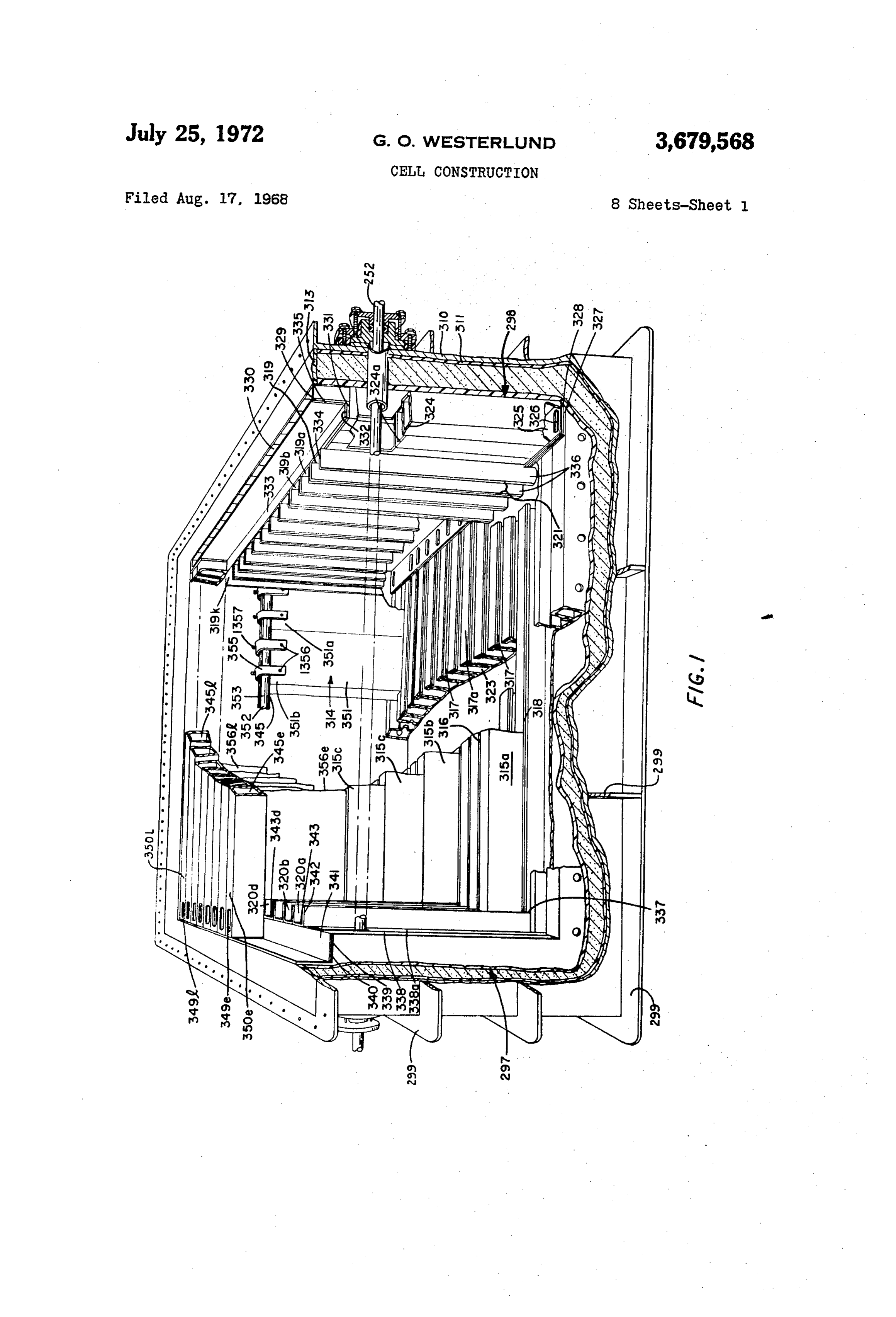
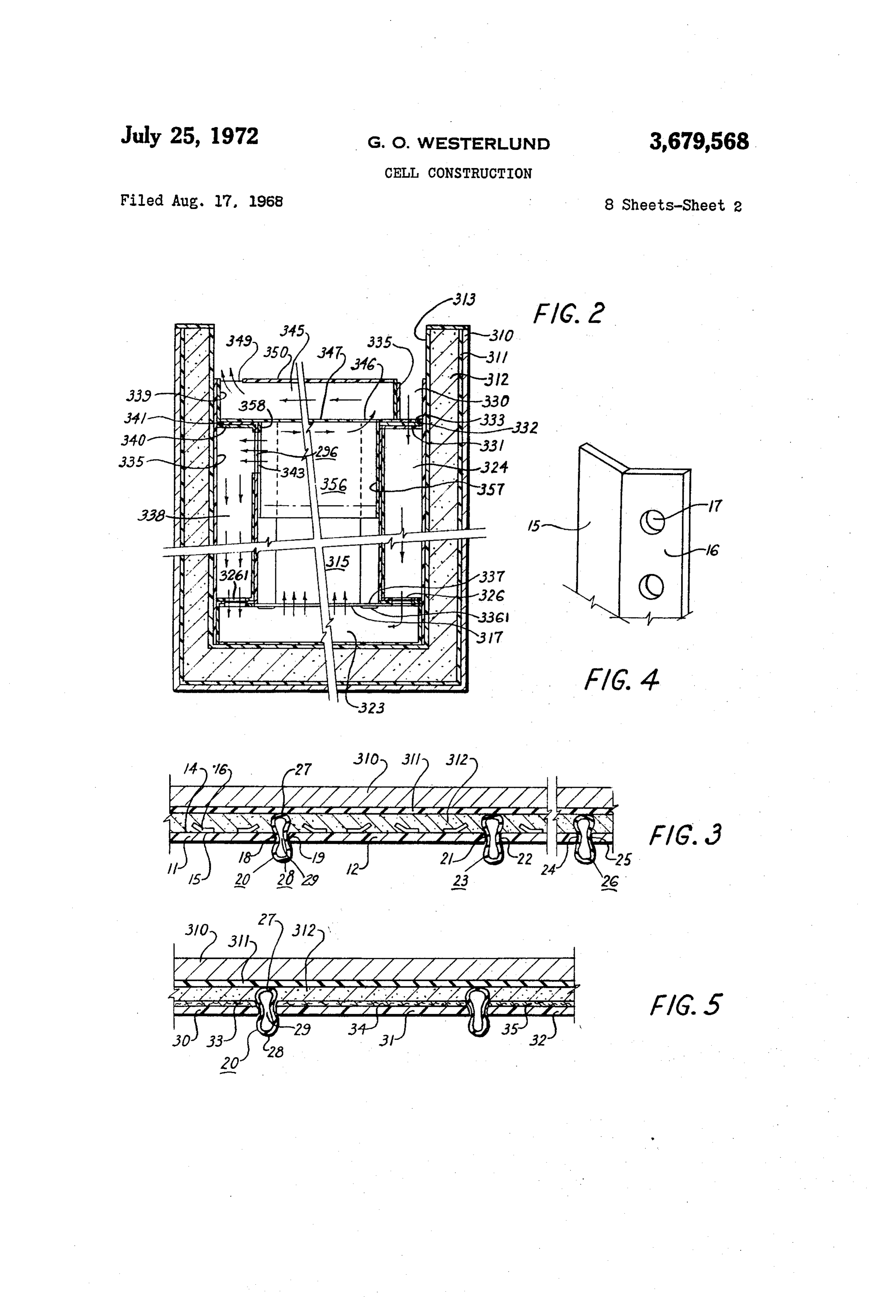
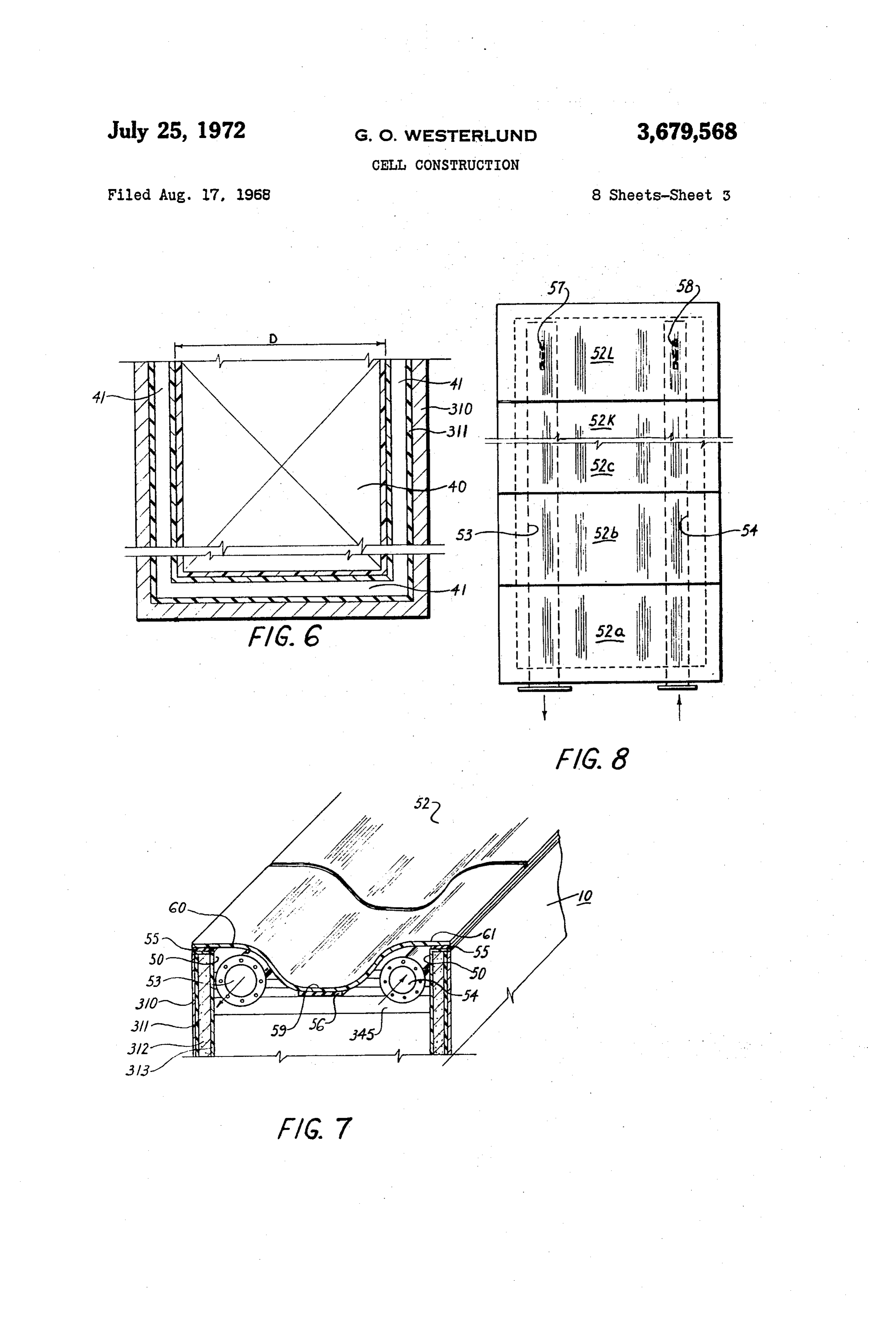
Means are also provided for permitting thermal expansion In the accompanying drawings: and/or contraction of the dividing wall and also of the FIG. 1 is an isometric view, partially broken away, of cell cover plate. an electrolytic cell of an aspect of this invention showing In addition, a cover is provided which is formed of a 40 the novel wall construction;
plurality of sub-units with joints provided for lengthwise FIG. 2 is a central longitudinal section through the thermal dimensional changes. There is, in fact, no limita cell of FIG. 1;
tion as to the size of the overall cover. Since the cover is FIG. 3 is a section through a typical wall structure of preferably formed of smaller sections, this enables easy the cell of FIGS. 1 and 2;
maintenance and manpower handling, rather than the use 45 FIG. 4 is an isometric view of the typical anchor plate of hoists, cranes, etc. when a large size single cover is used in the wall constructions shown in FIG. 3; used. Special types of clamps are used for clamping the FIG. 5 is a section through another embodiment of a sub-units of the cover sections together. The cover is typical wall structure which may be used in the cell of also preferably secured to the top profiles by a special FIGS. 1 and 2;
CaS. 50 FIG. 6 is a schematic representation of the technique The cover is particularly adapted to provide a manifold used to construct the novel cell structure; or header for the inlet liquor and an outlet manifold or FIG. 7 is an isometric view of the electrolytic cell of header for the product transferred from the cell, i.e. the another aspect of this invention showing the novel cover electrolyte containing entrained and/or occluded gas structure;
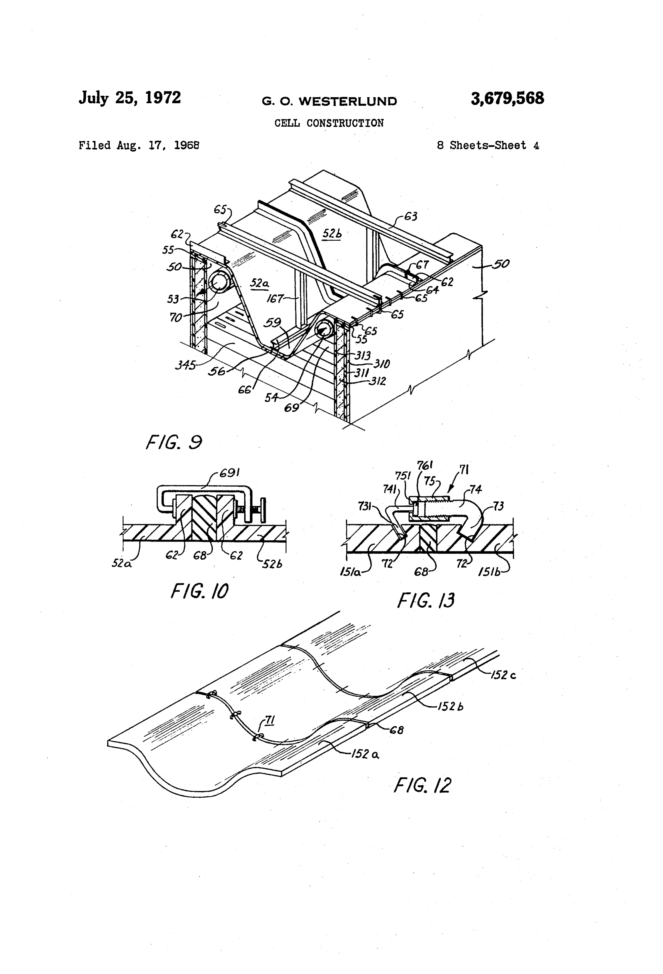
bubbles. The cover is designed so as to maintain sufficient 55 FIG. 8 is a plan view of the electrolytic cell of FIG. 7; liquor velocity to provide a turbulent flow. This ensures FIG. 9 is an isometric view of a detail of the electrolytic no substantial gas separation. The pipe inserts of the out cell cover of an aspect of this invention; let header may have their openings facing the top of the FIG. 10 is a section through the electrolytic cell cover cover. If no such insert pipes are included, the outlet of FIG. 9 showing the manner of clamping the cover would be provided near the highest elevation, e.g. at one 60 Sections together;
FIG. 11 is a central transverse section of another elec side of the tank.
It is also desirable to incline the cover towards the out trolytic cell of an aspect of this invention showing the let to provide an approximately constant product velocity. cover and manifold structure of a further aspect of the The product flow from the individual cells would ac present invention;
cumulate as the cover inclines, thus maintaining less pres 65 FIG. 12 is an isometric view of the electrolytic cell sure drop throughout the cell. Thus, the inclined cover cover of another aspect of this invention; is an integral part of the outlet manifold for the purpose of FIG. 13 is a section through the electrolytic cell cover maintaining sufficient product velocity and for assuring of FIG. 12 showing the manner of clamping the cover that there is no significant transfer of gaseous products. sections together;
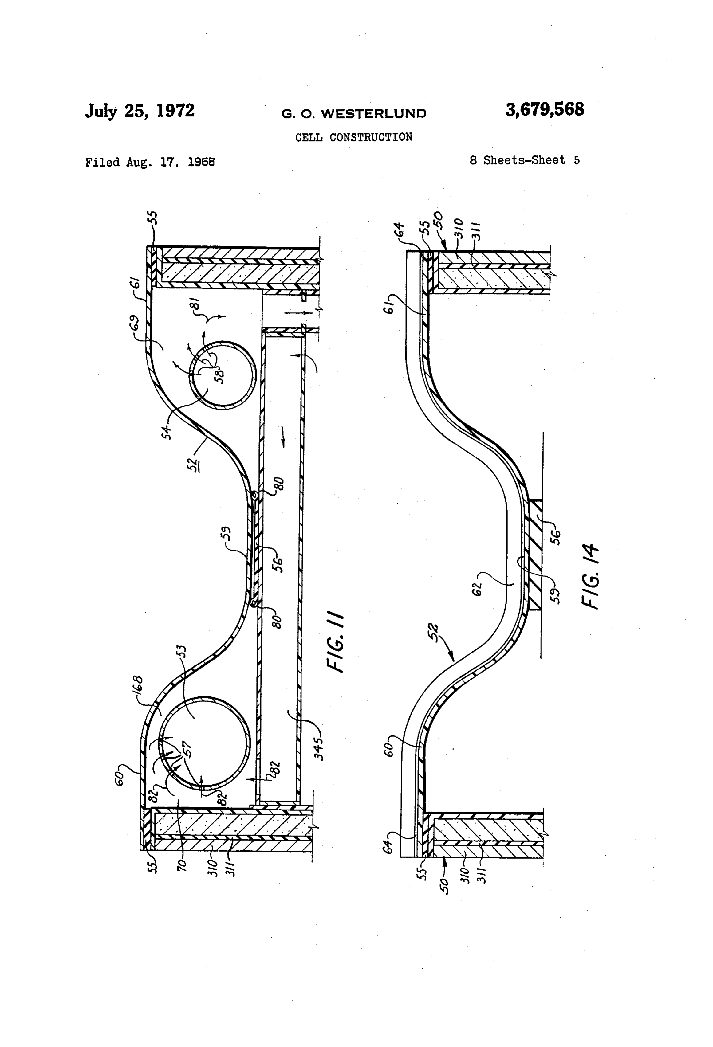
The pipe inserts are for the principal purpose of mini 70 FIG. 14 is a section through yet another electrolytic cell mizing current losses from the cell. The cross-sectional cover of another aspect of this invention; area of the piping, the length of the piping, constant FIG. 15 is a top plan view of a cover according to yet conductivity of the liquor and the potential difference all another aspect of this invention;
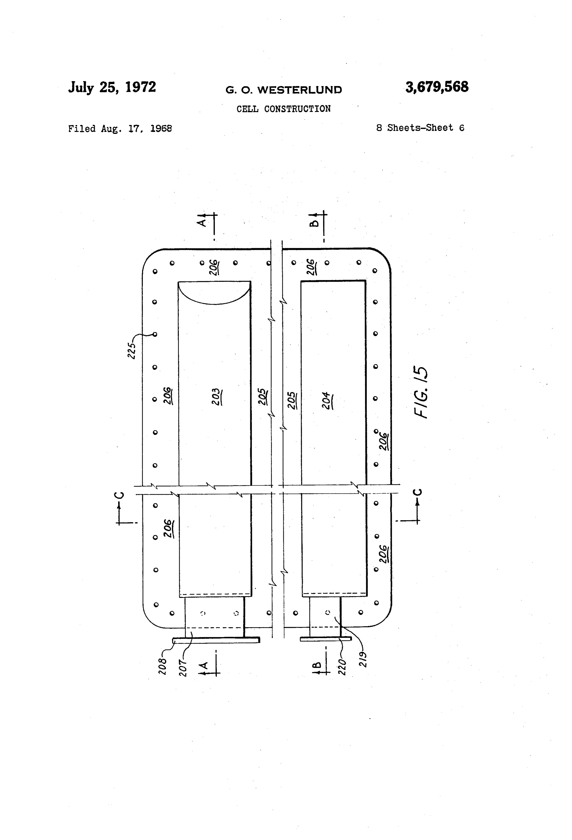
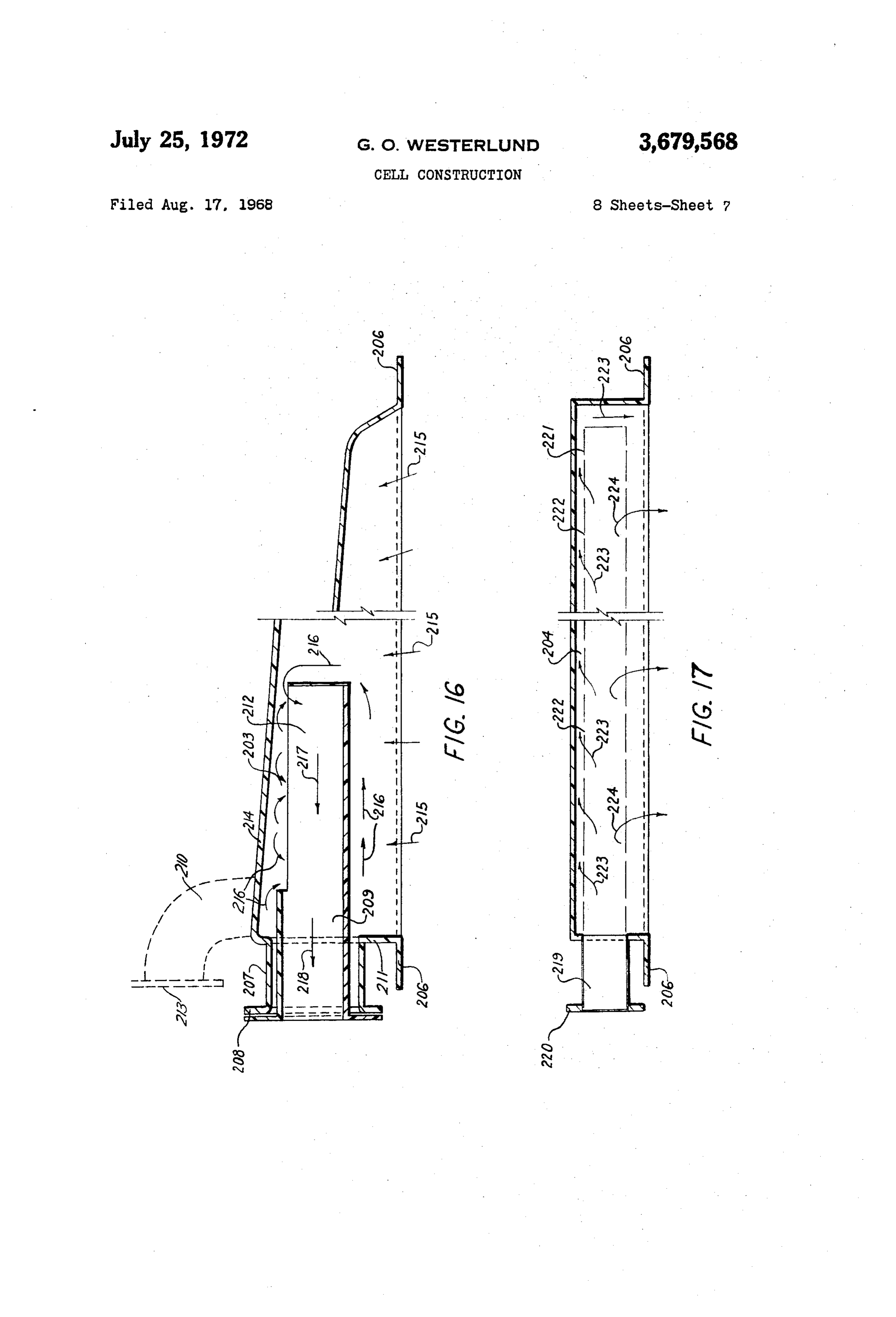
are interrelated to determine the precise value of the FIG. 16 is a section along the line A-A of FIG. 15; current leakage. Thus, by inserting the pipe inserts, appli 75 FIG. 17 is a section along the line B-B of FIG. 15;
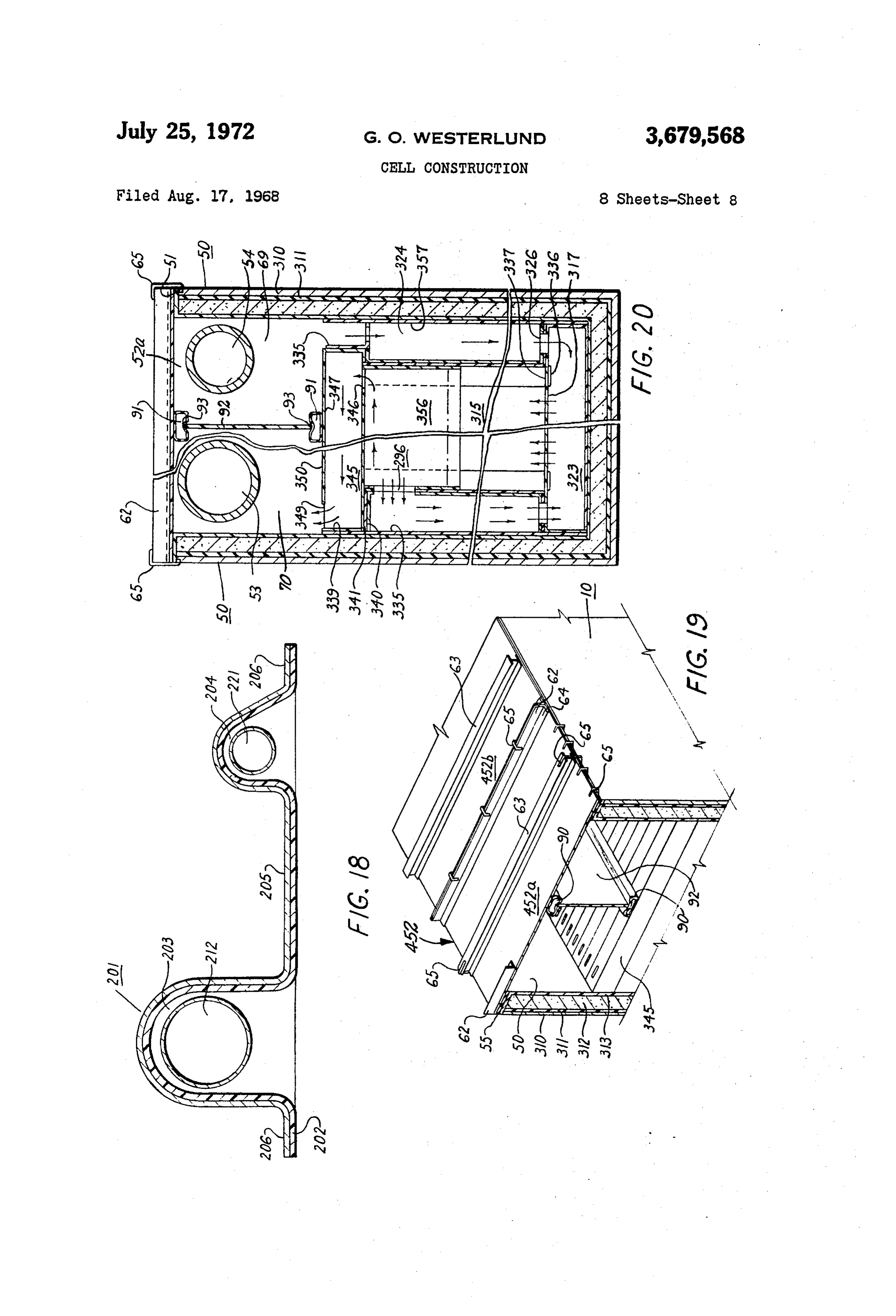
Page 14
FIG. 18 is a section along the line C-C of FIG. 15; 315b, 315c, 315d, etc. The slotted inlet means are spaced FIG. 19 is an isometric view of a detail of an electro apart by a distance 317 which is greater than the thick lytic cell cover of still another aspect of this invention; ness of the graphite bipolar electrodes 315a, 315b, 315c, and 315d, etc. in the stack. Thus, there is provided one stack FIG. 20 is a central transverse section through the cell of such electrodes 315a, 315b, 315c, 315d, etc. preferably of F.G. 19. situated between a pair of such slotted longitudinally ex Turning firstly to FIGS. 1 and 2, it is seen that the elec tending inlet means 317. The bottom bipolar electrode trolytic apparatus comprises a main, rigid, durable outer 315, of the stack 315a, etc. of each of the stacks rests upon shell 310, which may preferably be formed of steel. Such a sealing flexible and compressible chemically-resistant shell 310 is provided with a liner 311 which may be of O gasket 318 which may be formed of natural rubber, natural rubber, "Hypalon (the trademark for chlorosul “Hypalon,” of other suitable material.
fonated polyethylene, a synthetic rubber), or other suit Each stack in the plurality of stacks of bipolar elec able material which affords both electrical and chemical trodes 315a, 315b, 315c, 315d, etc. is located and posi resistance. Disposed on the inside, as an inner lining of tioned within the module by means of a pair of diametri the cell, is a plastic sheet 313. The plastic material of 5 cally opposed, vertically disposed, U-shaped channel spac such sheet may be polyvinyl chloride, polyvinyl dichloride, ing members 319, 319a, 319b, 319c, etc. and 319k, and polyvinyl difluoride, polyethylene, polypropylene, Pen 320, 320a, 320b, etc. and 320k. The spacing 321 between ton, or methacrylates such as Plexiglas or Perspex. Dis the arms 336 of the U-shaped channel spacing member posed between the inner lining 313 and the rubber liner is equal to the thickness of the graphite bipolar electrodes 311 is a mortar, grout, or polyester-type cement 312. The 20 315a, 315b, 315c, 315d, etc. These U-shaped channel steel outer shell 310 is braced and rigidified by mutually members 319, 319a, 319b, etc. and 319k, and 320, 320a, transverse flanges 299 forming a grid on the outer surface 320b, etc. and 320k are situated adjacent opposite end of the wall. walls 298, 297 of the module, and are formed of a chemi The substantially cell-liquor-inert chemically-resistant cally and electrically-resistant material such as polyvinyl plastic lining 313 also serves the important function of 25 chloride, polyvinyl dichloride, polyvinyl difluoride, poly maintaining close tolerances of the dimensions within the ethylene, polypropylene, etc.
cell. This serves to minimize current leakage between the The slotted bottom inlet channels 317 for each of the adjacent rods 352 where a plurality of rods are provided. interelectrode spaces 316 are individually fed from their Only two of such rods are shown in FIG. 1. respective inlet bottom manifolds 323. The feed inlet to The electrolytic cell of this aspect of the present inven 30 the bottom manifolds 323 may be of any type. Prefer tion is based on a modular construction. While the em ably, however, it consists of a plurality of vertically dis bodiment of FIGS. 1 and 2 shows only one module, name posed channels 324, 324a, 324b, etc. equal in number to ly between the two rods 352, the cell unit may comprise the number of stacks of bipolar electrodes 315a, 315b, any number of modules, each electrically connected either 315c, etc., i.e. equal to one less than the number of inter in parallel or in series as may be desired. If they are con 35 electrode chambers 316 within the electrolytic chamber nected in parallel, alternate bipolar electrodes will be con of the module. The plurality of such vertically disposed nected individually to an anode bus bar and to a cathode channels 324, 324a, 324b, etc. is situated within the main bus bar. If, however, the modules are connected in series, shell 310 and is disposed in a vertical direction along side it is only necessary to have an alternatively varying ar wall 298, namely disposed btween the plastic cell lining rangement of anode-cathode-anode, etc. 40 313 and the U-shaped channel spacing members 319, Each module of this aspect of the present invention 319a, 319b, 319c, etc. The vertically extending channels comprises a pair of spaced apart monopolar electrodes 324, 324a, 324b, etc. are provided with a common bottom 314 and a plurality of closely spaced bipolar electrodes plate 325 rigidly and permanently secured thereto, the 315. Each of the bipolar electrodes 315 is provided by a bottom plate being provided with a plurality of slotted plurality of vertically stacked longitudinally disposed apertures 326, therein to communicate with each of inlet graphite electrodes 315a, 315b, 315c, 315d, etc. The 45 manifolds 324. A common bottom sealing plate 327 is also graphite electrodes 315a, 315b, 315c, 315d, etc. may be rigidly secured to the bottom manifolds 323, and this joined together between their longitudinally extending plate, in addition, has a plurality of slotted apertures (not top and bottom faces in a manner as set forth in appli shown, but corresponding to apertures 326) therein. Dis cant's earlier issued Canadian Pat. No. 714,778. Alterna 50 posed between the sealing plate 325 of the inlet channels tively, the individual graphite electrodes 315a, 315b, 315c, and the sealing plate 327 of the bottom manifold is a 315d, etc. in the stack, may be adhered together at their slotted gasket 328, the slots being in registry with the joints to provide a chemically-resistant joint by using a slots 326, in the sealing plate 325 and the registering slots suitable cement to fill the voids between the plates when in plate 327. The slotted sealing plates 325 and 327 and they are assembled. The cement would solidify as a solid 55 the gasket 328 are each made of a suitably chemically gasket seal. A suitable type of cement is a polyvinyl chlo and electrically-resistant material such as rubber, polyvinyl ride cement but other cements or compounds could be chloride, polyvinyl dichloride, polyvinyl difluoride, poly used, such as polyesters or various types of rubbers or ethylene, polypropylene, etc.
plastics. Disposed at the top of inlet channels 324, 324a, 324b, The lowermost graphite bipolar electrode in the stack, 60 324c, etc. is an L-shaped member, the vertical portion namely 315a, may be mounted on the bottom of the tank 329 thereof defining a common inlet header 330 for the in a manner taught in applicant's earlier issued Canadian inlet conduits 324, 324a, 324b, 324c, etc. The horizontally Pat. No. 741,778. However, an alternative construction extending leg 331 of the L-shaped member extends in which will be described hereinafter may also be used. Simi wardly into the cell as far as the U-shaped channel mem larly, the upper bipolar electrode in each stack, namely 65 bers 319, 319a, 319b, 319c, etc. and provides a ledge 332 315c, may be rigidly secured within the module in a man whose purpose will be described hereinafter. Disposed on ner as described in applicant's earlier issued Canadian Pat. the ledge 332 is a sealing gasket 333 of a suitable chem No. 741,778. On the other hand, it may be held in place ically-resistant rubbery material. This sealing gasket is in a manner to be described hereinafter. disposed a slight distance above the upper ends 334 of the Each module consists of a plurality of electrolyte cham 70 U-shaped channel members 319, 319a, 319b, 319c, etc. bers or inter-electrode spaces 316, each of the chambers Secured to the inner face of the vertically extending leg having a longitudinally extending slotted inlet 317 to pro 329 of the L-shaped member is a sealing liner 335 of a vide for the entry of the electrolyte to each chamber 316. suitable chemically and electrically-resistant material. Thus, each electrolyte chamber 316 is bounded on its sides The lower portions 3361 of the legs of each of the U by the opposed side faces of the stack of electrodes 315a, 75 shaped channel members 319, 319a, 319b, 319c, etc. ex
Page 15
tend below the sealing plate 325 of the inlet channel to non-conductive and chemically-resistant plastic material which the U-shaped channel members are attached. This such as polyvinyl chloride, polyvinyl dichloride, polyvinyl depending extension 3361 is adapted to provide a flange difluoride, polyethylene, polypropylene, etc. Each of the which enters a key-way 337 provided in the upper face chemically inert and electrically non-conductive divider 37a of the bottom manifold 323 leads to the longitudinal plates 356, 356a, 356b, etc. consists of a longitudinally ly extending inlet channel 317 of each module. This co extending plate provided at one end with a cross-plate operation, therefore, assists in locking the inlet conduit 357 which is selected to be of the same width as each sub-assembly in the desired position. of the stacked bipolar graphite electrodes 315, 315a, 315b, The other plurality of U-shaped channel members 320, etc. The cross-piece 358, at the other end of the longitu 320a, 320b, 320c, etc. are connected to a respective and O dinally extending electrically non-conducting divider corresponding plurality of recirculatory conduits 338, plates 356, 356e, 356l is provided with a slot 343, in reg 338a which, in their bottom structure, are identical with istry with a corresponding slot 296, such slots leading to the bottom structure of the inlet conduits 324, 324a, 324b, the recirculatory conduits 338, 338a, 338b. Also mounted 324c, etc. and will not, therefore, be described further. at the upper portion of each of the longitudinally extend However, the upper portion of each of the recirculatory 15 ing divider plates 356, 356e, 356l is a longitudinally ex conduits 338, 338a, is provided with a sealing closure tending hollow top profile header 345, 345e, each pro plate 339 rigidly secured to the top thereof to provide a vided with the aforementioned slotted opening 346, in the ledge 340. Ledge 340 is provided with a sealing gasket respective lower faces 347, at a position adjacent the inlet 341 superimposed thereon, the eventual height of the conduits 324, 324a, of the electrolytic apparatus. The gasket 341 being slightly higher than the upper extremity 20 longitudinally extending top profile headers 345, 345e, 342 of the U-shaped channels 320, 320a, 320b, 320c, etc. 345l are each provided with the aforementioned slotted which are attached to the recirculatory conduits 338, 338a. outlet aperture 349, 349e, 349l in the respective upper The recirculatory conduits are connected at the upper faces 350, 350e, 350l adjacent the recirculatory conduits reaches thereof to the respective upper liquor chamber 338, 33.8a. The slots 349, 349e, 34.9l discharge to an out provided between adjacent divider plates 356, etc. and by 25 let manifold (which is not shown in FIGS. 1 and 2). means of respective slots 343. The internal circulation within the cell is shown more Vertically extending non-electrically active liquor cham clearly in FIG. 2 and depicted schematically by the vari bers provided between adjacent divider plates are con ous arrows. The electrolyte and liquor enter by inlet con nected to longitudinally extending top profile headers 345, duit generally indicated as 324 and are distributed to flow 345e, 345 by means of slotted communicators 346 on the 30 upwardly from manifolds generally indicated as 323 via bottom face 347 of the top profile headers 345, 345e, slots generally indicated as 317. The lighter liquor and 345l. Liquor is discharged into outlet manifold (not electrolyte containing entrained gaseous products of elec shown) through slotted outlets 349, 349e, 34.9l in the trolysis move upwardly from slot generally indicated as upper diametrically opposed surfaces 350, 350e, 350l. 37 to the lower face generally indicated as 347 of top thereof. The chambers provided between adjacent divider profile header generally indicated as 345 until it reaches plates 356, 356a, 356b, 356c, etc. also discharge into re outlet slot generally indicated as 346. Then the liquor circulatory conduits 338, 338a, by means of slots 296 travels through top profile header generally indicated as which register with slot 343. 345 and through slot generally indicated as 349 to a mani As is conventional with bipolar electrolyte cells, the fold which is not shown. Some of the lighter liquor and lateral terminal stacks of bipolar 315 electrodes are each 40 electrolyte moving upwardly from slot generally indicated situated adjacent a monopolar electrode 314. The mono as 317 is caused to enter recirculatory conduit generally polar electrode 314 consists, in one embodiment hereof, indicated as 338 through slots generally indicated as 343 of a plurality of vertically extending graphite electrodes and slots generally indicated as 296. Such liquor and elec 351, 351a. These graphite electrodes extend throughout trolyte now flow downwardly in recirculatory channel gen the entire operative electrolytic height of the electrolytic 45 erally indicated as 338 to slot generally indicated as 3261, module electrodes. One of the electrodes 314 is the anode where it enters manifold generally indicated as 323 to be and the other of the electrodes is the cathode, and it is redistributed and recirculated through elongated slot gen irrelevant which electrode is the cathode or the anode. erally indicated as 317. Thus, within the cell, flow is by It is preferred that each of the connectors 252 which con means of forced external circulation by liquor pumped nect the monopolar electrode 314 to the positive or to the 50 downwardly in conduit generally indicated as 324, and negative poles comprises a solid core 352 of high elec forced upwardly through slot generally indicated as 317. trical conductivity, namely of copper, aluminum, or other In addition, flow is provided through the inter-electrode Suitable electrical conducting material. The core 352 is spaces generally indicated as 316, upwardly into enlarged sheathed with a tube of an electrically conducting, chem non-electrolysis channel generally indicated as 344, and ically-resistant material 353 such as titanium, zirconium, 55 downwardly through recirculatory conduit generally in or the like. A 180 segment of the circumference of the dicated as 338.
chemically-resistant tube is platinized at 345 so that all Turning now to FIGS. 3 and 4, it is seen that the cell areas of contact between the graphite monopolar elec walls are made up of a steel outer shell 30, a rubber or trode 314 and the connector 252 is through a platinum-to other chemically-resistant liner 31 adherent to the steel carbon connection. The connection is assured by méans 60 shell, an inner plastic lining 313, and mortar 312. The of U-clamps 355 rigidly secured, as by titanium bolts inner plastic lining 313 is made up of a plurality of dis 1356, to the graphite electrodes 351, 351a, and to the con crete and finite sized plastic sheets 11, 12, 3, etc. Each nector 252 by means of titanium bolts 1357. The electrode plastic sheet is provided with a plurality of plastic anchors passes out the side walls of the electrolytic apparatus through a gland structure which is shown in FIG. 1 but 65 composed of a first face 15 secured, as by heat sealing, to which will not be described further. the inside face 14 of each of plastic sheetings 1, 12, 13, To recapitulate, each electrolytic sub-cell is provided etc. The plastic anchor also includes a second face 16 ex with an electrolyte chamber 316 which is longitudinally tending outwardly from face 15 at an angle greater than bounded by the bipolar stacked electrodes 315a, 315b, 90, i.e. at an angle of about 120. Face 16 is provided 315c, 315d, etc. or alternatively by the bipolar electrode 70 with some means to ensure adequate adhesion of the mor stack and a monopolar electrode 314. The sub-cell also tar 313 to the face 16. As shown in FIG. 4, these means includes a non-electrolysis chamber defined between ad comprise a plurality of apertures 17 in the face 16. How jacent divider plates 356 wherein the products of the elec ever, alternative means, such as a roughened surface on trolysis accumulate, the chamber being longitudinally face 16, or barbs or prongs, etc. may be provided on face bound by plates 356e, 356l formed of suitable electrically 75 16.
Page 16
The wall, as shown in FIG. 3, is designed to provide for central trough portion 59 which is sealingly engaged with thermal expansion and/or contraction. For this reason, the top profile headers 345 by means of a sealing mem special joints have been provided which serve a dual pur ber 56. The cover also includes a pair of elevated lips pose, namely to permit such thermal expansion and/or 60 and 61 which are sealingly engaged to the top edge contraction in both the plastic sheeting 312 and the mor of the side fanges 50 by means of sealing member 55. tar 313 and also to seal against the profile assemblies (i.e. Disposed in the space between the top profile headers U-shaped channel members generally indicated as 319 and 345 and the lip portion 60 is an outlet insert header pipe 320) and thus minimize current leakages. As shown in 53 and similarly disposed in the space between the top FIG. 3, a plurality of resiliently deformable members 20, profile header 345 and the lip 61 is an inlet insert header 23, 26, etc. are provided. Member 20 is disposed between O pipe 54. Communication between the intlet distributors the marginal side edge 18 of sheet 11 and the marginal generally indicated in FIGS. 1 and 2 as 349 of the top side edge 19 of sheet 12; member 23 is disposed between headers 345 and the outlet insert header pipe 53 is pro the marginal side edge 21 of sheet 12 and the marginal vided by a plurality of outlet openings 57. side edge 22 of sheet 13; member 26 is disposed between One auxiliary purpose of the outlet header pipe insert marginal side edge 24 of sheet 13 and marginal side edge 53 and the inlet header pipe 54 is to minimize current 25 of a further plastic sheet; etc. The resiliently deform losses from the cell. The current leakage is determined able members 20, 23, 26, etc. may be formed of natural by the cross-sectional area of the piping, the length of the or of synthetic rubber, and are preferably hollow. They piping, the conductivity of the liquor within the cell, may, however, also be formed of closed cell sponge rub and the potential difference. Thus, by inserting the pipe ber, or hollow plastic tubings. When in use, the members 20 inserts 53 and 54 a "length” is artificially created which include an inner head portion 27, an outer head portion has a dramatic effect on the current leakage. Moreover, 28, and an intermediate neck portion 29. The neck portion this length takes up very little space, is virtually main 29 may be made larger or smaller automatically depend tenance free and has a minimal pressure differential. ing upon the thermal expansion and/or contraction of While the outlet insert header pipe 53 and the inlet insert the plastic sheetings 11, 12, 13, etc. Inner head 27 is com 25 header pipe 54 are shown within the cell cover, these pressible as required to provide a satisfactory seal against could also be externally located pipes, with a communi the rubber liner 31 of the outer cell wall 310. Inner head cation through the cell cover to outlet openings 57 and 28 is compressible and seals against the profile assembly, inlet openings 58.
such as U-shaped channel members generally indicated FIGS. 9 and 10 show one manner in which the various as 319 and generally indicated as 320, shown in FIGS. 1 30 segments 52a, 52b, 52c, etc. of the cover 52 may be and 2. secured together. It is noted that in FIGS. 9 and 10, each FIG. 5 shows another embodiment of a cell wall con of the segments 52a, 52b is provided with flange 62 in struction which is an alternative to the construction shown cluding a rim 64 which is shaped to conform to the curva in FIG. 3. In this case, the plurality of discrete and finite ture of the cover. The flanges appear at the terminal edges sized plastic sheetings 30, 31, 32, etc. are provided on their 35 of the segments 52a, 52b. As seen more clearly in FIG. back faces with a fiberglass coating 33, 34, 35, etc. Thus, 10, a seal and expansion/contraction joint 68 formed of when the mortar 312 is placed between the plastic sheet rubber, closed cellular sponges, rubber foam, etc. is dis ing 30, 31, 32, etc. and the rubber liner 311 of the steel posed between the upright faces of the flanges 62. A shell 310, the mortar can penetrate into the interstices clamp 691 of conventional design and construction is of the fiberglass 33, 34, 35, etc. and form a firm bond to 40 employed to hold flanges 62 together. the plastic sheetings 30, 31, 32, etc. In all other construc The cover sections 51a, 52b, are placed on the top of tional details, the wall structure shown in FIG. 5 is the the side wall fange extensions 50 with a sealing means 55 same as the wall structure shown in FIG. 3. of natural or synthetic rubber, closed cellular sponges, or FIG. 6 illustrates, in rather diagrammatic form, one sponge rubber, etc. disposed therebetween. The cover is way in which the improved electrolytic cell of an aspect 45 then clamped to the side wall flange extensions 50 by of this invention may be formed. It is seen that the struc means of clamps 65. A plurality of transverse beams 63, turally rigid outer shell, comprising the steel shell 310 e.g. formed of steel, are disposed atop the cover 52 at and the rubber liner 31, is provided with a jig 40 which spaced locations and are clamped to the flange extension is of the precise dimensions desired for the interior of 50 by means of clamps 65. The trough portion 59 of the the cell. For example, the jig may be the precise dimen 50 cover is placed on top of the top headers 345 with a seal sions "D" of the length of the bipolar electrodes generally ing means 56 formed of natural or synthetic rubber, closed indicated as 315 and the respective U-shaped sealing cellular sponges, sponge rubber, etc. disposed therebe channels generally indicated as 319 and generally indi tween (see FIG. 14). A longitudinal beam 66 formed of cated at 320. The jig is disposed within the cell so that a steel or plastic or aluminum or any other suitable mem space 41 is provided for the later introduction of the mor 55 ber is placed in the trough section 59 superposed over the tar. The plurality of discrete plastic sheetings 11, 12, 13, flanges 62 at the trough portion. Vertically extending etc., as well as the expansion members 20, 23, 26, etc., means 167 are provided between the lower surface of are placed within the cell and with their front faces touch transverse beams and the upper surface of longitudinal ing the exposed surfaces of the jig. Thus, the plastic sheet beam 66 in the trough portion 59. One suitable such ing to provide lining 313 is installed against the jig. The 60 means is a jack. In this way, an electrolyte seal is provided mortar 312 is then poured behind the plastic sheeting into between the surfaces of the cover which contact the top space 41, the mortar thus filling the voids. When the mor profile headers 345. This provides, in effect, an inlet tar has set, the jig is removed and the cell construction is manifold section 69 which contains the inlet insert header formed. Since the jig provides the precise internal dimen pipe 54 and an outlet header section 70 which contains sions of the cell, it is not necessary to maintain a close 65 the outlet insert header pipe 53.
tolerance for the exterior of the cell; in other words, it is not essential to have an accurately dimensioned rubber tionFIG. 11 shows a typical cross-section of the upper por of the cell showing the structure and operation of the coated steel outer shell.
FIGS. 7, 8, and 9 are directed to the improved electro electrolytic cell cover. The sealing means 56 includes lateral bulbous sealing edges 80 to provide enhanced seal lytic cell cover. As shown in FIGS. 7, 8 and 9, the cell 70 itself, indicated generally by reference numeral 10, is ing noted with the bottom surface of trough section 59. It is that the liquor inlet manifold 69 is provided with provided with elevated side wall flanges 50 and elevated a liquor inlet insert header pipe 54 which is provided with end wall flanges (not shown) which are curved to pro a plurality of liquor outlets 58. These outlets are disposed vide proper sealing between the cover 52 and the end in the first quadrant (i.e. in the upper right-hand corner flanges. It is seen that the cover 52 is provided with a 75 as viewed in FIG. 11) of the circular cross-section pipe
Page 17
54 so that the liquor which is pumped into the liquor inlet Penton, Plexiglas or Perspex. However, it is preferred that insert header pipe 54 is caused to assume the flow path the lining be a natural or synthetic rubber. The rubber shown by arrows 81. This provides an efficient means for may be: a soft rubber of Shore Adurometer hardness 30 admission of fresh liquor electrolyte into the electrolytic 50; a semi-hard rubber of Shore Adurometer hardness of cell. It is preferred that the outlet apertures 58 be disposed 50-100; or a hard rubber of Shore Adurometer hardness near the terminal end of the inlet header pipe 54 in order above 100.
to provide the maximum increase in electrical resistance by To achieve the desired strong bond between the main the additional length of the insert. Although the apertures outer cover section 201 and the liner 202, the section 201 may be holes, it is also possible to provide outlet means by is first thoroughly cleaned and roughened, e.g. by being means of slots. 10 Sandblasted. Then a primer cement, e.g. an epoxy base The cell is also provided with an outlet manifold 70 in cement, is used to adhere the preformed rubber lining 202 which is disposed an outlet insert header pipe 53. The pipe to the section 201. To achieve optimum bonding, it is pre is provided with inlet openings 57 only in the fourth ferred to cure the section-cement-rubber unit by steam quadrant (i.e. in the upper left-hand corner as viewed in pressure.
FIG. 11) in order to maintain turbulent flow outside the 5 The cover section 201 is provided with a protruding out insert pipe 53, thereby substantially avoiding gas separa let manifold 203 and a protruding inlet manifold 204, sep tion. The openings 57 are preferaby provided near the arated by a substantially flat sealing section 205. The terminal end of the insert header pipe 53 in order to in cover section 201 is also provided with a circumferential crease the electrical resistance by the length of the in sealing flange 206.
sert. Although the openings may be apertures, it is also 20 As shown more clearly in FIG. 16, the outlet mani possible to provide the inlets to the header pipe 53 by fold 203 is provided with an aperture in wall 211 through means of slots. By providing a configuration and struc which extends an outlet coupling pipe 207 having a cou ture as shown, the path of the outlet electrolyte follows the pling flange 208, by which the outlet manifold 203 may arrows 82. be connected to the conventional recirculatory and/or FIGS. 12 and 13 show an alternative way of clamping 25 product recovery systems (not shown).
cover sections 152a, 152b, 152c, etc. together. As shown Disposed within and connected to outlet coupling pipe in these two figures, the cover segments 152a, 152b, 152c, 207 is a hollow cylindrical insert 209 terminating in a etc. are of somewhat thicker gauge and are provided with closed-ended, open-topped trough 212. This insert is for a plurality of anchor holes 72 situated adjacent the lateral the purpose of assuring high liquor level within the out edges and sloping downwardly towards the lateral edges. 30 let manifold 203 in cases where the liquor is being trans The anchor holes are thus disposed adjacent the marginal ferred externally to the outlet coupling pipe 207 and/or edges of the segments 152a, 152b, 152c, etc. The clamps, discharged at lower elevation than the top of outlet mani shown generally as 71, include a clamping “V” which in fold 203. Furthermore, the pipe insert 209 also serves to cludes three elements. The first element includes a leg minimize and control current leakage from the cell. It is 73 which is adapted to project into the anchor hole 72 noted that the outlet manifold 203 preferably has a uni of segment 151b and an arm 74 which is externally thread formly increasing cross-sectional area relative to the di ed. The second element is a coupling nut 75, which is in rection of outward flow of cell liquor, i.e. it has a slop ternally threaded to engage threads on 74 and has an ing roof 214. The roof is sloped in order to maintain apertured end 751. The third element includes a leg 731 Sufficiently high velocity to maintain the liquor in substan which is adapted to project into the anchor hole 72 of 40 tially turbulent flow within manifold 203, thereby sub segment 751a and an arm 741 which projects through stantially avoiding separation of entrained and/or oc apertured end 751 with a retaining button 761 within cluded gases from the cell liquor. coupling nut 75. Disposed between the marginal edges of As an alternative, as shown by the broken lines, instead each of cover segments 152a, 152b, 152c, etc. is the expan of outlet coupling pipe 207 extending through an aper sion/contraction joint 68. Coupling nut 75 is threaded onto 45 ture in wall 212, an aperture may be provided in roof 214 the external threads on arms 74 in order to bring the at its highest point, and an outlet elbow 210 may be dis arms closer together and provide an adequate coupling of posed therein. Outlet elbow 210 also terminates in a cou cover segments 152a, 152b, 152c, etc. pling flange 213. Outlet elbow 210 assures flooded condi FIG. 14 shows in cross-section form, one manner of tions even when there is no flow through outlet mani providing the cover 52. It it seen that the cover 52 is 50 fold 203.
curved to provide a substantially flat trough portion 59 It will be noted, therefore, that the path of outwardly whose bottom surface is adapted to rest on rubber sealing flowing cell liquor with entrained and/or occluded gase means 56, curving upwardly to lateral flat tip portions ous products is upwardly from the cell into the manifold 60 and 61, the bottom of lip portions 60 and 61 resting 203 (as shown by arrows 215), and longitudinally along upon the elevated side flange 50 with a rubber seal 55 55 the manifold 203 to enter the closed-ended, open-topped disposed therebetween. The cover portions 52 are rigidi trough 212 (as shown by arrows 216). The liquor then fied and are simultaneously provided with means for flows in trough 212 to the pipe insert 209 out of coupling clamping adjacent segments together by means of a flange pipe 207 (as shown by arrows 217 and 218) or alterna member which is bent to fit the curved configuration of Sy. if preferred, upwardly out through coupling elbow the cover 52 and which is provided with a vertically up 60 10.
standing marginal flange portion 62 and a horizontally As more clearly seen in FIG. 17, the inlet manifold 204 extending embracing flange portion 64. is provided with an inlet coupling pipe 219 having a cou Turning now to FIG. 15-18, it is seen that this novel pling flange 220. The inlet manifold 204 may, if desired cell cover comprises a main outer cover section 201, pro to minimize and control the current leakage wtihin the vided with a liner 202, of substantially cell-liquor-inert 65 cell, be provided with an inlet pipe insert 221 (shown in rigid material, such as a glass fiber reinforced resin, e.g. broken lines). If such insert pipe 221 is provided, it has a polyester. Alternatively, it may be a conventional steel an apertured top section 222, whereby electrolyte flow cover first lined with an intermediate lining of a glass fiber follows arrows 223 upwardly into and longitudinally along reinforced polyester resin and then with an exposed lin inlet manifold 204, to enter the cell as shown by down ing of rubber. Furthermore, it may be formed of a plastic 70 Wardly extending arrow 2231. On the oher hand, if no material, such as polyvinyl chloride, polyvinyl dichloride, such insert pipe 221 is provided, the electrolyte flow fol polyvinyl difluoride, polyethylene, polypropylene, Penton, lows arrows 224.
Plexiglas or Perspex. The lining 202 may be formed of The cover 201 may be secured to the electrolytic cell by a plastic material such as polyvinyl chloride, polyvinyl di means of bolts (not shown) passing through holes 225 chloride, polvinyl difluoride, polyethylene, polypropylene, 75 in flange 206 and in registering holes in a top flange of the
Page 18
cell. This construction of the cell is shown more clearly whereby, on removal of the cover, said, manifolds are in FIG. 1. simultaneously removed, thereby leaving the electrolytic FIGS. 19 and 20 show an alternative embodiment of cell open for inspection and/or repair. the cover of an aspect of this invention. It will be ob 2. The combination claimed in claim 1 wherein said served that the cover 452 is composed of segments 452a, cover is formed out of plastic material. 452b which are clamped together and clamped to the top 3. The combination claimed in claim 2 wherein the flange of the elevated side wall flange 50 of the cell 10 plastic material is polyvinyl chloride, polyvinyl dichloride, in the same manner as has been previously described with polyvinyl difluoride, polyethylene, polypropylene, a chlo respect to FIGS. 9 and 10 by means of clamps 65. It is rinated polyether, or a thermoplastic arcylic resin. noted, however, with respect to the cover of FIGS. 19 and O 4. The combination claimed in claim 1 wherein said 20 that the cover elements 452a, 452b are formed of cover is formed out of plastic-lined fiberglass reinforced substantially flat sheet members. Disposed approximately S.
along the central longitudinal axis of the cell and rest 5. The combination claimed in claim 1 wherein said ing on, and secured to, the upper surface of the top cover is formed out of rubber-lined fiberglass reinforced profile headers 345 is an expansible gripping and retain 5 polyester.
ing means 90. Similarly disposed along the central longi 6. The combination claimed in claim 1 wherein said tudinal axis on the underface of the cover sections 452a, cover is formed of steel, lined first with an intermediate 452b is a cooperating expansible gripping and retaining liner of a fiberglass reinforced resin and then with an means 91. Each of the gripping and retaining means 90 exposed lining of rubber.
and 91 comprises a hollow, essentially tubular member 20 7. The combination claimed in claim 1 wherein the provided with a central longitudinally extending depres outlet manifold has a uniformly increasing cross-sectional sion 93. Seated within the opposed depressions 93 is a area, relative to the direction of outward flow of mixed central longitudinally extending dividing wall 92. Because cell liquor and gaseous products of electrolysis. of the resilient nature of the gripping and retaining means 8. The combination claimed in claim 1 wherein said 90 and 91, any expansion and/or contraction of the di 25 cover includes a pair of elevated sections separated by a vider wall 93 is accommodated by the expansible and depressed section, sealing members at the inner surface retractible nature of means 90 and 91. Thus, the divid of the edges of the elevated sections and at the inner sur ing wall 92 satisfactorily divides the portion below the face of the depressed section engaging the upper surface cover into an inlet manifold section 69 and an outlet of said electrolytic cell tank, thereby to provide said manifold section 70. 30 separate and distinct manifolds. The dividing wall 92 between the headers prevents short 9. The combination claimed in claim 8 wherein said circuiting of the liquor. Besides sealing against the top cover is formed out of plastic material. profile headers 345, it is seen that sealing is also provided 10. The combination claimed in claim 9 wherein the against the cover 452. The ends of the electrolytic cell plastic material is polyvinyl chloride, polyvinyl dichloride, tank are also sealed in a manner similar to that previously 35 polyvinyl difluoride, polyethylene, polypropylene, chlo described, i.e. by providing a vertically extending, central rinated polyether, or a thermoplastic acrylic resin. ly disposed, expansible sealing means similar to sealing 11. The combination claimed in claim 8 wherein said means 90 and 91. The dividing wall 92 is, therefore, re cover is formed out of plastic-lined fiberglass reinforced movable in order to make it possible to install the graphite S.
electrodes generally indicated as 315 and the top profile 40 12. The combination claimed in claim. 8 wherein said headers generally indicated as 345. It is also seen that pro cover is formed out of rubber-lined fiberglass reinforced vision has automatically been made to allow for thermal polyester.
expansion and/or contraction of the dividing wall 92 while 13. The combination claimed in claim 8 wherein said maintaining the adequate liquor-tight seal. cover is formed of steel, lined first with an intermediate The dividing wall 92 is formed of cell-liquor-inert ma 45 liner of a fiberglass reinforced resin and then with an ex terial. Examples of suitable materials include polyvinyl posed lining of rubber.
chloride, polyvinyl dichloride, polyvinyl difluoride, poly 14. The combination claimed in claim 8 wherein the ethylene, polypropylene, Penton and methacrylates such outlet manifold has a uniformly increasing cross-sectional as Plexiglas and Perspex, etc. area, relative to the direction of outward flow of mixed By aspects of this invention, therefore, an improved 50 cell liquor and gaseous products of electrolysis. cell has been provided in which is incorporated a novel 15. The combination claimed in claim 8 wherein, in said cover:
cell wall structure and/or a novel cover member. This provides enhanced durability of the cell and ease of con (a) the depressed section includes a central longitudi struction of the celi. nally extending depressed trough portion; and From the foregoing description, one skilled in the art 55 (b) the pair of elevated sections include a pair of lateral can easily ascertain the essential characteristics of this longitudinally extending raised lips co-extensive with invention, and without departing from the spirit and scope the side walls of the trough portion; thereof, can make various changes and modifications of and wherein the sealing members include: the invention to adapt it to various usages and conditions.
Consequently, such changes and modifications are prop 60 (c)inner sealing members sealingly engaged between the lowermost surface of the trough portion and the erly, equitably, and "intended' to be, within the full range upper surface of an auxiliary cover element disposed of equivalence of the following claims. within the electrolytic cell tank; and I claim:
1. An electrolytic cell comprising, in combination, an (d) sealing members sealingly engaged between the electrolytic cell tank and a cover, the cover comprising: 65 inner surfaces of the lips and the upper surface of three spaced apart sealing members sealingly engaged to opposed walls of the electrolytic cell tank. an upper surface of said electrolytic cell tank, said seal 16. The combination claimed in claim 15 wherein ing members thereby cooperating with a structure on said said cover is formed out of plastic material. upper surface of said electrolytic cell tank to provide a 17. The combination claimed in claim 16 wherein the separate and distinct inlet manifold for the inlet of liquor 70 plastic material is polyvinyl chloride, polyvinyl dichloride, to said electrolytic cell tank and a separate and distinct polyvinyl difluoride, polyethylene, polypropylene, a chlo outlet manifold for the outlet of liquor and gaseous prod rinated polyether, or a thermoplastic acrylic resin. ucts of electrolysis from said electrolytic cell tank, the 18. The combination claimed in claim 15 wherein said inner exposed surfaces of the cover including a material cover is formed out of plastic-lined fiberglass reinforced selected from the group consisting or rubber and plastics; 75 CS
Page 19
19. The combination claimed in claim 15 wherein said tional area, relative to the direction of outward flow of cover is formed out of rubber-lined fiberglass reinforced mixed cell liquor and gaseous products of electrolysis. polyeter. 35. The combination claimed in claim 1 wherein the 20. The combination claimed in claim 15 wherein said outlet manifold is provided with an inwardly projecting cover is formed of steel, lined first with an intermediate hollow cylindrical insert adjacent the effluent port there liner of a fiberglass reinforced resin and then with an ex of to provide high liquor level within said manifold. posed lining of rubber. 36. The combination claimed in claim 1 wherein said 21. The combination claimed in claim 15 wherein the inlet and outlet manifolds extend along the longitudinal outlet manifold has a uniformly increasingy cross-sec axis of said electrolytic cell tank, and further including tional area, relative to the direction of outward flow of O an inlet pipe insert extending within the inlet manifold mixed cell liquor and gaseous products of electrolysis. along a predetermined length of the inlet manifold, where 22. The combination claimed in claim 15 including: a by to minimize current leakage in the cell. lateral beam clamplingly securing the lateral edges of 37. The combination claimed in claim 36, including an the cover to the top of the side walls of the electrolytic cell outlet pipe insert extending inwardly within the outlet tank; a longitudinally extending beam in association with 5 manifold along a predetermined length of the outlet the depressed portion; and means for urging the longi manifold, whereby to minimize current leakage in the tudinal and the lateral beams apart. cell.
23. The combination claimed in claim i wherein said 38. The combination claimed in claim 36 wherein the cover extends between said walls of said electrolytic cell communication between the inlet manifold and the inlet tank and further wherein said cover is provided as a plu pipe insert is provided by apertures in the area of the pipe rality of longitudinally abutting and secured segments. insert subtending an angle between 0 and 90. 24. The combination claimed in claim 23 wherein said 39. The combination claimed in claim 36 wherein the individual segments of said plurality of longitudinally communication between the outlet manifold and the out abutting and secured segments are provided with upstand let pipe insert is provided by apertures in the area of the ing marginal flanges, wherein a compressible material is 25 pipe insert subtending an angle between 270 and 360. disposed between flanges of adjacent segments, and where 40. The combination claimed in claim 36 wherein the in a clamp is provided for clamplingly securing the adja cover includes a pair of elevated sections separated by a cent flanges together. depressed section, with sealing members at the inner sur 25. The combination claimed in claim 24 wherein said face near the edges of the elevated sections and on the compressbile material is natural or synthetic rubber, 30 inner surface of the depressed section engaging with the sponge rubber or foamed cellular material. upper surface of an auxiliary cover within said electrolytic 26. The combination claimed in claim 23 wherein said cell tank, thereby to provide the separate and distinct individual segments of said plurality of longitudinally abut manifold chambers.
ting and secured segments are provided with means for 41. The combination claimed in claim 36 wherein the securing a clamp to each of the segments, wherein a flexi cover comprises:
ble compressible material is disposed between lateral (a) a central longitudinally extending depressed trough edges of the adjacent segments and wherein a coupling portion;
nut is provided for securing the clamps together. (b) a pair of lateral longitudinally extending raised lips 27. The combination claimed in claim 1 wherein said co-extensive with the side walls of the trough por cover includes a flat plate section, sealing members at the 40 tion;
edges thereof sealingly engaging upward extensions of (c) sealing members sealingly engaged between the mutually opposed walls of said electrolytic cell tank, and inner lowermost surface of the trough portion and a longitudinally extending dividing plate disposed between the upper surface of an auxiliary cover element dis the bottom surface of said flat plate section and the upper posed within the electrolytic cell tank; and surface of an auxiliary cover element disposed within (d) sealing members Sealingly engaged between the said electrolytic cell tank, thereby to provide the separate inner uppermost surfaces of said lips and the upper and distinct manifold chambers. surface of opposed walls of the electrolytic cell tank. 28. The combination claimed in claim 27 including: 42. The combination claimed in claim 36 wherein the sealing members sealingly engaged between the upper Sur cover includes a flat plate section, sealing members at the edges thereof sealingly engaging upward extensions of mu face of said auxiliary cover element disposed within said 50 tually opposed walls of said electrolytic cell tank, and a electrolytic cell tank and the lower marginal edge of the longitudinally dividing plate to provide for thermal changes of size of the bottom surface extending dividing plate disposed between said longitudinally extending plate; and sealing members of said flat plate section and the upper sealingly engaged between the upper marginal edge of the surface of an auxiliary cover element within said electro dividing plate and the lower surface of said cover in order 55 lytic cell tank, thereby to provide the separate and dis tinct manifold chambers.
to provide for thermal changes of size of said longitudinal 43. The combination claimed in claim 42 including: ly extending plate.
29. The combination claimed in claim 27 wherein said sealing members sealingly engaged between the upper sur cover is formed out of plastic material. face of said auxiliary cover member within said electro 30. The combination claimed in claim 29 wherein the 60 ing lytic cell tank and the lower marginal edge of the divid plate to provide for thermal changes of size of the plastic material is polyvinyl chloride, polyvinyl dichloride, dividing polyvinyl difluoride, polyethylene, polypropylene, a chlo between the plate; and sealing members sealingly engaged rinated polyether, or a thermoplastic acrylic resin. upper marginal edge of the dividing plate 31. The combination claimed in claim 27 wherein said and the lower surface of the cover in order to provide for cover is formed out of plastic-lined fiberglass reinforced 65 thermal changes of size of the dividing plate. 44. The combination claimed in claim 36 wherein the
32. The combination claimed in claim 27 wherein said inlet manifold is adapted to communicate with a plurality cover is formed out of rubber-lined fierglass reinforced of inlet conduits for feeding electrolyte to a plurality of polyester. cell units; and wherein the outlet manifold is adapted to 33. The combination claimed in claim 27 wherein said 70 communicate with a plurality of outlet ducts for with cover is formed of steel, lined first with an intermediate drawing electrolyte from a plurality of cell units. liner of a fiberglass reinforced resin and then with an ex 45. The combination claimed in claim 44 wherein the posed lining of rubber. inlet manifold has a uniformly increasing cross-sectional 34. The comination claimed in claim 27 wherein the area, relative to the direction of outward flow of mixed outlet manifold has a uniformly increasingly croSS-Sec cell liquor and gaseous products of electrolysis.
Page 20
46. The combination claimed in claim 44 wherein the 57. The combination of claim 52 wherein the mortar outlet manifold is provided with an inwardly projecting filler (c) is a cement containing alumina, lime, silica, me hollow cylindrical insert adjacent the effluent port there tallic iron, magnesia and ferrous oxide. of to provide high liquor level within said manifold. 58. The combination of claim 52 including an anchor 47. The combination claimed in claim 1 wherein said for anchoring the plastic sheeting to the mortar, the electrolytic cell tank includes a plurality of longitudi anchor including a surface adapted to be bonded to the nally extending, spaced apart bipolar electrodes and two plastic sheeting and a second surface disposed at an lateral, longitudinally extending monopolar electrodes, angle to the first surface provided with means for secure the space between adjacent electrodes constituting an bonding to the mortar.
electrolytic cell unit; inlet means for admitting liquor into O 59. The combination of claim 58 wherein the second each of the electrolytic cell units; a top header providing surface of said anchor is provided with a plurality of an outlet for liquor from each of the electrolytic cell units, apertures.
and further wherein one of the sealing members of the 60. The combination of claim 52 wherein the plastic cover is sealingly engaged with the top header. material (b) is provided with an integral, pervious lining 48. The combination of claim 47 wherein the cover to enhance the anchoring of the mortar thereto. includes a pair of elevated sections separated by a de 61. The combination of claim 60 wherein the said per pressed section, with sealing members at the inner sur vious lining is made of fiberglass.
faces of the edges of the elevated sections and on the inner 62. The combination of claim 52 wherein said inner surfaces of the depressed section engaging with the upper lining (b) is composed of a plurality of finite sheets of surface of said top header within said electrolytic cell 20 substantially chemically inert plastic material disposed tank, thereby to provide the separate and distinct mani within the outer structurally rigid shell a predetermined folds. distance from the shell, and disposed in vertical and/or 49. The combination of claim 47 wherein the cover horizontal arrays and including:
comprises: (d) resiliently deformable sealing members disposed (a) a central longitudinally extending depressed trough 25 between the adjacent marginal edges of vicinal finite portion; plastic sheetings, such resiliently deformable men (b) a pair of lateral longitudinally extending raised bers extending beyond a selected face of the sheeting lips co-extensive with the side walls of the trough por as far as the inner face of the outer structurally rigid tion; shell, and extending beyond the outer face of the (c) sealing members at the inner lower-most surface 30 finite plastic sheeting into the interior of the cell. of the trough portion for sealing engagement with 63. The combination of claim 62 wherein the outer the upper surface of an auxiliary cover element dis shell (a) is a rubber-lined steel tank.
posed within the electrolytic cell tank; and 64. The combination of claim 62 wherein the outer (d) sealing members at the inner uppermost surfaces shell (a) is a fiberglass-reinforced polyester tank. of the lips for sealing engagement with the upper 35 65. The combination of claim 62 wherein the plastic surface of opposed walls of the electrolytic cell tank. material (b) is polyvinyl chloride, polyvinyl dichloride, 50. The combination of claim 47 wherein the cover polyvinyl difluoride, polyethylene, polypropylene, a chlo includes a flat plate section, sealing members at the edges rinated polyester or a thermoplastic acrylic resin. thereof sealingly engaging upward extensions of mutually 66. The combination of claim 62 wherein the mem opposed walls of the electrolytic cell tank, and a longi 40 bers (d) are formed of natural rubber, synthetic rubber, tudinally extending dividing plate disposed between the foam rubber or polyethylene or polypropylene. bottom surface of the first plate section and the upper 67. The combination of claim 66 wherein the mem surface of an auxiliary cover member within said elec bers (d) are hollow tubes.
trolytic cell tank. 68. The combination of claim 62 wherein the mortar 51. The combination of claim 50, including sealing 45 filler (c) is a polyester resin.
members sealingly engaged between the upper surface of 69. The combination of claim 62 wherein the mortar said auxiliary cover member within said electrolytic cell filler (c) is a cement containing alumina, line, silica and tank and the lower marginal edge of the dividing plate small amounts of metallic iron, magnesia and ferrous ox to provide for thermal changes of size of the dividing plate, ide.
and sealing members sealingly engaged between the upper 50 70. The combination of claim 62 including an anchor marginal edge of the dividing plate and the lower surface for anchoring the plastic sheeting to the mortar, the an of the cover in order to provide for thermal changes of chor including a surface adapted to be bonded to the size of the dividing plate. plastic sheeting and a second surface disposed at an angle 52. The combination of claim 47 wherein the cell wall to the first surface provided with means for secure bond construction comprises: 55 ing to the mortar.
(a) an outer structurally rigid shell; 71. The combination of claim 70 wherein the sec (b) an inner lining of a substantially chemically inert ond surface of said anchor is provided with a pluraltiy plastic material disposed at accurately predetermined of apertures.
locations within the shell; and 72. The combination of claim 62 wherein the plastic (c) a mortar filler bonded to the shell and anchored 60 material (b) is provided with an integral, pervious lining to the lining; to enhance the anchoring of the mortar thereto. wherein accurate tolerances for the dimensions of the 73. The combination of claim 72 wherein the pervious electrolytic cell are provided in order to minimize cur lining is made of fiberglass.
rent leakage within the cell. 74. The combination of claim 1 wherein the wall con 53. The combination of claim 52 wherein the outer 65 struction of said electrolytic cell tank comprises: shell (a) is a rubber-lined steel tank. (a) an outer structurally rigid shell; 54. The combination of claim 52 wherein the outer (b) an inner lining of a substantially chemically inert shell (a) is a fiberglass reinforced polyester tank. plastic material disposed at accurately predetermined 55. The combination of claim 52 wherein the plastic 70 locations within the shell; and material (b) is polyvinyl chloride, polyvinyl dichloride, (c) a mortar filler bonded to the shell and anchored polyvinyl difluoride, polyethylene, polypropylene, a chlo to the lining;
rinated polyester or a thermoplastic acrylic resin. wherein accurate tolerances for the dimensions of the 56. The combination of claim 52 wherein the mortar electrolytic cell are provided in order to minimize cur filler (c) is a polyester resin. 75 rent leakage within the cell.
Page 21
75. The combination claimed in claim 74 wherein the of plastic material disposed within the outer structurally outer shell (a) is a rubber-lined steel tank. rigid shell a predetermined distance from the shell, and 76. The combination claimed in claim 74 wherein the disposed in arrays and including:
outer shell (a) is a fiberglass reinforced polyester tank. (d) resiliently deformable sealing members disposed 77. The combination claimed in claim 74 wherein the between the adjacent marginal edges of vicinal finite plastic material (b) is polyvinyl chloride, polyvinyl di plastic sheetings, such resiliently deformable mem chloride, polyvinyl difluoride, polyethylene, polypropyl bers extending beyond a selected face of the sheet ene, a chorinated polyether or a thermoplastic acrylic ing as far as the inner face of the outer structurally S1. rigid shell, and extending beyond the other face of 78. The combination claimed in claim 74 wherein the 10 the finite plastic sheeting into the interior of the cell. mortar filler (c) is a polyester resin.
79. The combination claimed in claim 74 wherein the References Cited mortar filler (c) is a cement containing alumina, lime, UNITED STATES PATENTS silica, metallic iron, magnesia and ferrous oxide. 1,185,407 5/1916 Jenkins ------------ 204-270 80. The combination claimed in claim 74 including an 5 2,075,688 3/1937 Zdansky ------------ 204-256 anchor for anchoring the plastic lining to the mortar, the 2,816,070 12/1957 Buchanan ---------- 204-279 anchor including a surface adapted to be bonded to the 2,958,635 11/1960 De Nora ----------- 204-279 plastic lining and a second surface disposed at an angle 3,247,090 4/1966 Forbes ------------- 204-256 to the first surface provided with means for secure bond 3,252,883 5/1966 Schick ------------- 204-279 ing to the mortar. 20 3,318,792 5/1967 Cotton et al. -------- 204-279 81. The combination claimed in claim 80 wherein the second surface of said anchor is provided with a plu 3,450,621 6/1969 Anderson ----------- 204-279 rality of apertures. FOREIGN PATENTS 82. The combination claimed in claim 74 wherein the 156,393 1962 U.S.S.R. ------------ 204-279 plastic material (b) is provided with an integral, pervi 25 643,624 1937 Germany --------- 204-195 G ous lining to enhance the anchoring of the mortar there to. TA-HSUNG TUNG, Primary Examiner 83. The combination claimed in claim 82 wherein said pervious lining is made of fiberglass. U.S. C. X.R. 84. The combination claimed in claim 74 wherein said 30 52-309, 573, 597, 622; 204-95, 255, 256, 268, 275, inner lining (b) is composed of a plurality of finite sheets 278, 279; 264-35
Provenance
- Collection
- Cited prior art
- Original PDF
- patentimages.storage.googleapis.com →
- Filed
- 1968-09-17
- Pages
- 21
- Method
- pdftotext (the PDF's own text layer) + pdftoppm 300dpi page scans
- Source
- Google Patents bibliographic record
- Granted
- 1972-07-25
- Inventors
- Gothe O Westerlund; CHEMETICS INTERNATIONAL
- Transcribed from
- patentimages.storage.googleapis.com →