patent · US5577492A
Collimating TIR lens with focusing filter lens
26 November 1996
Page 1 — bibliographic record
III USOO5577492A
IIHIIII
United States Patent 19 11 Patent Number: 5,577,492 Parkyn, Jr. et al. (45) Date of Patent: Nov. 26, 1996 54 COLLMATING TRLENS WITH FOCUSING 4,194,949 3/1980 Stark. FILTER LENS 4,198.953 4/1980 Power ................................. 126/699 X 4,282,858 8/1981 Bowers, Jr. 126/699 X (75) Inventors: William A. Parkyn, Jr., Torrance; 4,299,201 11/1981 Tsubota ............................... 126,700 X David G. Pelka, Los Angeles, both of 4,337,759 7/1982 Popovich et al..
Calif. 4,755,921 7/1988 Nelson.
4,803,608 2/1989 Dashwood .......................... 362/339 X 4,805,984 2/1989 Cobb, Jr. ................................. 385/33 73) Assignee: TR Technologies, Inc., Carson City, 5,059,013 10/1991 Jain ......................................... 359/503 Nev. 5,150,966 9/1992 Nelson.
5,38,309 1/1995 Borchardt .................................. 362/31 (21) Appl. No.: 415,274 5,486,983 1/1996 Cordier et al....................... 362/260 X 22 Filed: Apr. 7, 1995 FOREIGN PATENT DOCUMENTS
Related U.S. Application Data 1325087 8/1973 United Kingdom.
(63) Continuation-in-part of Ser. No. 869,003, Apr. 16, 1992, Pat. 1546792 5/1979 United Kingdom. No. 5,404,869. 1546793 5/1979 United Kingdom. (51) Int. Cl. ................................... F24, 2/08 1557472 12/1979 United Kingdom. (52) U.S. Cl. ............... ... 126/698; 126/699; 126/700; 1561129 2/1980 United Kingdom.
362/336; 362/260; 362/339 2239940 2/1993 United Kingdom.
(58) Field of Search ..................................... 126/698, 699, 126/700; 362/2, 16, 326, 327, 328,336–337, Primary Examiner-Larry Jones 339, 340, 800, 359-360,363, 293, 311 Attorney, Agent, or Firm-William W. Haefliger
References Cited 57 ABSTRACT
energy transmitting body structure; the structure comprising 1,421,506 7/1922 Limpert. multiple elements, each of which acts as a radiant energy 1,676,464 7/1928 Ryan ................................... 362/.336 X redirecting module, having on its cross-sectional perimeter 1,782,732 11/1930 Lebby ..................................... 362/.336 an entry face to receive incidence of the energy into the 2,254,961 9/1941 Harris...................................... 362/.336 interior of the perimeter, an exit face to pass the energy to 2,469,080 5/1949 Rosin et al. ... 362/.336 X the exterior of the perimeter in a direction towards the 3,425,056 1/1969 Dawson .............................. 362/.336X 3,915,148 10/1975 Fletcher et al.. reverse side of the body from the side of the incidence, and 3,941,993 3/1976 Hubert . a Totally Internally Reflecting face angled relative to the 3,970,070 7/1976 Meyer et al. . entry and exit faces to redirect towards the exit face the 4,002,031 1/1977 Bell. radiant energy incident from the entry face; the body struc 4,022,186 5/1977 Northrup, Jr. . ture generally redirecting incident radiant energy towards a 4,050,789 9/1977 Herbert ............................... 126,698 X predetermined target Zone situated apart from and on the 4,074,704 2/1978 Gellert. reverse side of the body relative to the side of the incidence; 4,103,673 8/1978 Woodworth et al., and lens structure associated with at least one of the faces for 4,108,540 8/1978 Anderson et al. . redirecting radiant energy passing between the entry and exit 4,116,223 9/1978 Vasilantone. faces via the Totally Internally Reflecting face.
4,171,695 10/1979 Sletten . 23 Claims, 19 Drawing Sheets
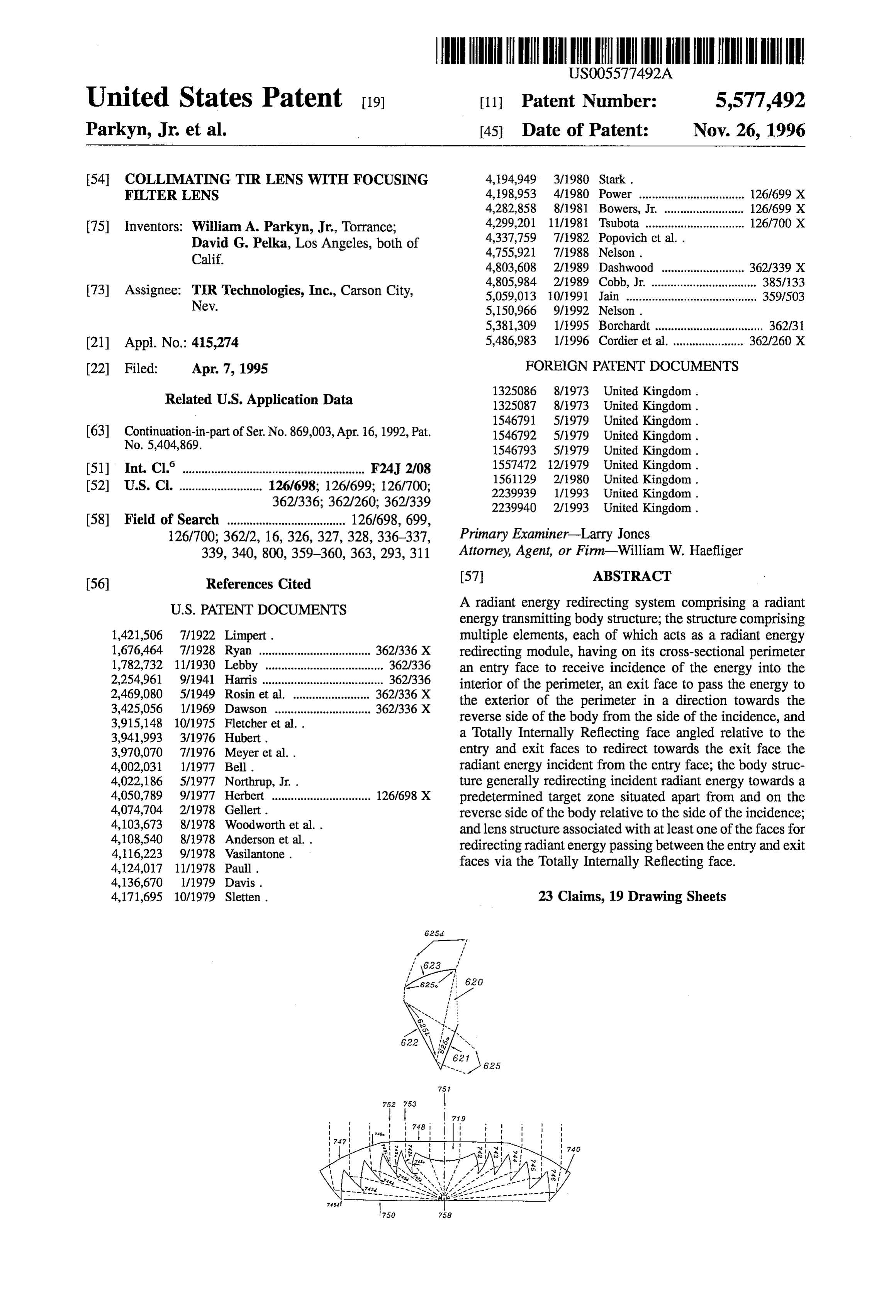
Page 2
Drawing sheet — no readable text.
Page 3
Drawing sheet — no readable text.
Page 4
Drawing sheet — no readable text.
Page 5
Drawing sheet — no readable text.
Page 6
Drawing sheet — no readable text.
Page 7
Drawing sheet — no readable text.
Page 8
Drawing sheet — no readable text.
Page 9
Drawing sheet — no readable text.
Page 10
Drawing sheet — no readable text.
Page 11
Drawing sheet — no readable text.
Page 12
Drawing sheet — no readable text.
Page 13
Drawing sheet — no readable text.
Page 14
Drawing sheet — no readable text.
Page 15
Drawing sheet — no readable text.
Page 16
Drawing sheet — no readable text.
Page 17
Drawing sheet — no readable text.
Page 18
Drawing sheet — no readable text.
Page 19
Drawing sheet — no readable text.
Page 20
Drawing sheet — no readable text.
Page 21
COLLMATING TRLENS WITH FOCUSING art, and to provide a means to collect and employ radiant FILTER LENS energy in a very cost-effective and efficient manner, using a new basic tool with applications that include the collection,
This application is a continuation-in-part of U.S. Ser. No. concentration, redirection, and wavelength separation of 07/869,003 filed Apr. 16, 1992, Now U.S. Pat. No. 5,404, radiant energy.
869. The present invention, which improves over the subject BACKGROUND OF THE INVENTION matter of U.S. Pat. No. 4,337,759, is basically characterized by the use of a transparent means employing elements to
This invention relates generally to radiant, particularly redirect radiant energy by means of TIR alone, or in con electromagnetic, energy concentration, redirection, and 10 junction with refraction, such means positioned between the manipulation, and improves over the subject matter of U.S. radiant energy source and a receiver. Each element redirects Pat. No. 4,337,759. It more particularly concerns apparatus radiant energy upon a common target Zone or Zones, during and method for employing a transparent lens means with the energy's internal passage through the element. A prop elements thereof using Total Internal Reflection (TIR), in erly oriented ray enters through the entry face and strikes the conjunction with a focusing second lens and a wavelength 15 reflective face, which redirects it toward the exit face, the selection filter, for use such as in laser spectrometry. three faces comprising the active faces for that ray. In Radiant energy is redirected to or from a predetermined addition, the lens means is associated with at least one of the Zone or zones; such redirection having a predetermined faces for redirecting radiant energy passing between the degree of concentration and/or chromatic dispersion. The entry and exit faces via the TIR face. zones have sources of light, as in photoillumination, or 20 Accordingly, the present invention is characterized by the radiant energy receiving means for conversion of the redi passage of redirected radiant energy entirely through the rected energy to thermal, electric, chemical, or mechanical transmitting body means and out the opposite side from forms. which it entered after transmission via associated lens The prior art of radiant energy concentration and illumi means. This invention constitutes a third class of radiant nation in general consists of two major types, as exemplified 25 energy concentrators that also has applications to other by refractive and reflective astronomical telescopes: a forms of radiant energy redirection than concentration, Such refractive lens positioned in front of a receiver or light as wavelength separation or collimation. Other surfaces of source, or a retro-reflective mirror positioned behind a the element may be inactive for the ray of interest (e.g., as receiver or light source. The corresponding devices in the 30 in solar energy concentration of relatively parallel rays) but prior art of solar energy concentration are the Fresnel lens may impinge upon improperly oriented rays (e.g., diffuse and the parabolic reflector, which focus solar energy on a skylight of off-angle sunlight).
target. Furthermore, there are non-imaging, reflecting con The TIR elements may be contiguous, forming a trans centrators that have the advantage of fixed daily (non parent cover means, or separated to allow undeflected light tracking) position with only seasonal adjustments, but the 35 to pass between them, for example to be focused by a mirror disadvantage of requiring relatively large reflector areas and upon the back of the target, which is thereby illuminated delivering only relatively low energy concentrations. from all directions.
Fresnel lenses are devices comprising purely refractive Each element may redirect all of the parallel rays entering elements, but they have physically inherent limitations of it into a single new direction, or split them into several redirecting radiant energy that give high flratios and bulky 40 directions, with or without wavelength separation, which concentrator structure. Moreover, linear Fresnel lenses have, can be controllably achieved by the independent, non for off-angles in the direction of the grooves, focusing errors, normal angling of the entry face and/or the exit face to the that are also inherent in the laws of refraction, and that limit parallel rays being redirected, or achieved by diffraction one-axis tracking configurations to relatively low concen gratings upon the exit face, which can be implemented by tration. 45 the replicative techniques of binary optics. Parabolic reflector concentrators have seen widespread While TIR alone is limited to incident angles greater than use, but are subject to losses of received radiant energy the critical angle and therefore to any redirective bend because the receiver is situated between the source and the angles less than 180°-2 critical angle (about 96 for acrylic), reflector, which is thereby shaded, preventing in particular additional redirection is possible with or without wavelength the utilization of large heat engines at the focus. Further 50 separation by the above-mentioned, non-normal angling of more, the receiver is exposed to environmental degradation the entry and exit faces. Such large bend angles enable a and thermal losses; and the inclusion of a protective trans given diameter transparent means to be much closer to the parent cover means about the receiver will merely reduce the target than a means limited to refraction alone, thereby system's optical efficiency. greatly reducing the necessary support structure. Further Another reflecting system has appeared in the literature, 55 more, a transparent means employing up to 90° bend angles as reported by Rabl in Solar Energy, Vol. 19, No. 5. It can utilize a flat mirror extending from the target to the rim employs a retro-reflecting means with elements that have of the means, thereby doubling solar concentration or dou two TIR faces to redirect radiant energy out the same side as bling intercept efficiency for a light source. it came in. Its only improvement over a metal mirror of the Since a given acceptance angle (of deviation from paral same shape is a potentially higher reflectivity; but the double lelism) produces a proportional requirement for target size, internal reflection doubles the sensitivity to manufacturing the target can be bisected by the plane of the mirror, and error over that of the present invention, which redirects result in an actual target of half the original size, with no radiant energy through itself with only a single reflection. decrease in acceptance angle, by insulating the half of the SUMMARY OF THE INVENTION target facing away from the redirected body means. Con 65 versely, the target can be doubled in size to give a doubled
It is a major object of the TIR lens to overcome the acceptance angle, and then halved by the mirror back to its above-described problems of, and difficulties with, the prior original area. This surprising potential for halving thermal
Page 22
losses is unique to the present invention, being unavailable pulling the lens from a mold (about 2). In the case of small for the parabolic reflector of 90° rim angle because the plane lenses with only a few facets, there is also the possibility of mirror would shade the aperture, and also unavailable for the an adjacent facet being larger or smaller than its neighbors, Fresnel lens because of its far lower rim angle. in order to raise the lens height and improve collimation. Unlike the Fresnel lens, chromatic aberration is com 5 The relative facet positions, as determined by the non pletely independent of bend angle and can have any positive, interference criterion, determine the overall lens profile, zero, or negative values desired for such wavelength-sepa which should be low or high depending upon the applica ration applications as solar illumination or bandgap-tailored tion. In a solar concentrator, the lens height should be photovoltaic cells. Unlike the parabolic reflector, the redi minimized to reduce spot size of the solar image. In a rective bend angle of an element is independent of its O converging or collimating TIR illumination system, it is location, greatly adding to design flexibility. (Since the advantageous to have somewhat more lens height, so that the parabolic reflector is a smooth continuum, there can be no apparent size of the source is reduced at the central facets, arbitrary variations in redirective bend angle from one spot and the output beam is thereby tightened. This consideration to a neighboring one.) does not hold for diverging TIR lenses, because only effi The first of the present invention's improvements over the 15 ciency, and not beam tightness, is required. subject matter of U.S. Pat. No. 4,337,759 is the curvature of An important use of facet curvature is in a small TIR lens the faces of the individual lens elements. This curvature may with only a few facets, such as a collimator for a light be provided at one, two or all three of the faces (entry, exit emitting diode. Molding very small facets may be undesir and TIR) and, for example, may constitute a concave entry able because of difficulties in making the mold. Curved facet face, a convex exit face, and/or a convex TIR face. faces enable relatively large facets to perform as accurately 20 as small ones. Lenses for light-emitting diodes are of interest
Radiant energy handling is thus improved over a flat for redlamps at the rear of automobiles. In fact, the TIR lens faceted face system, as for example in redirection of rays can be incorporated into the conventional transparent cover from a line or point source, within constraints of interior of an LED, greatly improving its luminous efficiency. shadowing and TIR face slope, to produce either parallel or converging output beams in a system using multiple faces. Further improvements over the subject matter of U.S. Pat. Also, improvements in ray collimation and focusing are 25 No. 4,337,759 are:
realized, and design freedom is enhanced, since each face A lens that redirects light from a source in order to focus can be individually curved or various combination of face it on a spot in front of the lens. curvatures can be employed to minimize aberrations, due to There are two reasons that the TIR lens is superior to the finite size of the facets. conventional ellipsoidal reflectors for this application. First, For ease of quality control of manufacturing, the curved 30 the lens and its associated planar back mirror collect all of facet faces can form spheres with centers on the axis of the output of a light source and focus it. The ellipsoidal rotational symmetry of the lens. When an axially symmetric reflector typically collects only a fourth of a source's output. lens is made by molding a rigid material, undercut interior Second, facet configurations are possible with efficient faces are precluded, which limits the curvature of those focusing power; that is, at the center of the focal spot, the faces. This constraint is not applicable to elastomeric lens 35 entire lens would appear to be as bright as the light source materials. itself, a condition known as "full flashing', important for the The facet design of the TIR lens has four degrees of proper functioning of microfiche and slide projectors. freedom: the angle of the entry face, the angle of the TIR Because of astigmatic aberrations inherent in the ellipsoidal face, the angle of the exit face, and the position of the reflector, it is never fully flashed, producing instead a much inwardly adjacent facet. A full design solution requires that 40 broader focal spot. Full flashing by the TIR lens is made four requirements be used to derive these four angles. In possible by faceting of the exit so that stairsteps have their many of the designs illustrated below, prearranged choices "risers' parallel to inner rays then emerging from the exit restricted the degrees of freedom. In general, however, the face. Then, the full exit face of the facet must be illuminated requirements are: by light from the TIR face, a condition that can be fulfilled 45 by curvature of the TIR face.
a) the redirection of light from source to target;
b) the full interception of light by the TIR face; Furthermore, the exit face can have about the same c) the full illumination of the exit face, for maximum refractive bending as the entry face, preventing unwanted thermodynamic efficiency; and image magnification that broadens the focal spot. The indi vidual convex curvature on each of the facet faces is vital to d) the non-interference of a facet's input and output rays 50 the success of this design:
by the next facet inwards. entry-face curvature enables the entire TIR facet to be Typically, a TIR lens is generated from the outermost, or utilized, through a slight convergence that prevents any rim, facetinwards in a facet-by-facet, numerically controlled light from missing the TIR face; iteration. The four requirements form a set of nonlinear TIR-face curvature enables the entire exit face to be equations in four unknowns to be solved for their roots. 55 illuminated, by preventing any light from striking the Because there is no general method of solving such equa tions, typical computer routines apply a matrix inversion stairstep risers or the adjacent TIR face; and method that assumes quasi-linearity in the neighborhood of exit-face curvature focuses light onto the target, eliminat the solution hyperspace. This requires some prior knowl ing the effects of finite facet size. edge of this hyperspace so that a starting point for the 60 This focusing configuration would have two prominent solution search is within the quasi-linear regime. This prior applications that considerably improve the light utilization knowledge depends upon whether the facet is triangular or efficiency of the prior art:
quadrilateral. The former give wider interfacet slot angles Imaging projectors for slides, motion pictures, or micro and thus are easier to make; but the latter add another degree fiche. Current designs use ellipsoidal reflectors that of freedom, enabling a wider choice of overall lens shapes. 65 have inherently low intercept efficiency (i.e., the frac The angle of this fourth, optically inactive, side of the tion of the source output that actually ends up in the facet would typically be set at the minimum draft angle for output image of the device).
Page 23
S 6
The TIR lens of the present invention can be used in symmetry over the circular cross-section of the toroidal conjunction with an aspheric lens in order to remove the lamp. The complete lens would be a figure of revolution with cosine-4th illumination non-uniformity typical of the prior its axis being that of the toroid rather than the center of the art. This version of the TIR lens typically has stepped exit lens profile. The more slender the toroidal lamp, the better faces, with the risers angled parallel to the converging rays, could its light be controlled by the lens. to ensure spatial continuity of the focal cone. The faces of Presently, there are no reflectors that can collect the light the facets can be curved so as to augment the action of the of such a lamp and put most of it into a forward-going beam. auxiliary lens. This toroidal TIR lens would be very useful for battery Another advantage of the TIR lens for this application is powered fluorescent lanterns, which currently cannot pro that it azimuthally smears out any structure in the 10 vide any focusing whatsoever.
source, removing a source of pattern noise that is A collimating TIR lens made of silicon. Because of the inherent in the imaging action of an ellipsoidal reflec high refractive index of this material, the refractive tOr. faces of its facets would be somewhat differently Illumination injector for optical fiber bundles and light 15 angled than those of a glass lens. The application for a pipes. Prior arthere also uses ellipsoidal reflectors. The - silicon lens is for the collimation of infrared light and TIR lens would have a focal cone half angle matched the exclusion of visible light (because silicon absorbs to the acceptance angle of the target. all wavelengths shorter than 1.1 micrometers). The Light-gathering means for spectrometers that analyze the purpose of this application is the jamming of the diffusely emitted light of samples that have been stimu 20 guidance sensors of heat-seeking, anti-aircraft rockets by focused beams of pulsating infrared light. The prior lated to produce Raman or fluorescent light. art uses much less efficient parabolic reflectors in Conventional spectrometers typically collect this light conjunction with a silicon window. The silicon TIR with microscope objectives, which also deliver tightly lens would be an important new kind of infrared focused (50 micrometers) laser light to the sample. These illuminator, as found in many night-vision systems. objectives typically have a focal length equal to their diam 25 The superiority of the present invention can be seen in its eter, so that they subtend about 50 and collect 5% of the application to prisms with curved cross sections, arrays of diffusely emitted output. connected linear or toroidal prisms acting in concert, redi The converging TIR lens can collect over half of this rection of rays from a line or point source, concentration of emission, a factor of ten improvement, greatly aiding spec spherical or plane waves, better collimation than parabolic tral analysis because of the greater signal to noise ratio. 30 mirrors, and more efficient focusing than ellipsoidal mirrors. A TIR lens that redirects light from a source in order to Another object of the invention is to provide a radiant form a diverging cone of light, as in floodlighting energy redirecting system comprising:
applications. For cone angles of 45 or less, this lens is a) a radiant energy transmitting body means, more efficient than a conventional congruent reflector b) that means comprising multiple elements, each of and much more compact. This divergence can either be 35 which acts as a radiant energy redirecting module, for uniform illumination, or it can take the appearance having on its cross-sectional perimeter an entry face to of effectively coming from a virtual source located receive incidence of the energy into the interior of the behind the lens, with appropriate facet-face curvatures perimeter, an exit face to pass the energy to the exterior compensating for the different distances of the facets of the perimeter in a direction towards the reverse side from the source.
Two types of linearly symmetric TIR lenses for cylindri of the body from the side of the incidence, and a Totally Internally Reflecting face angled relative to the entry cal sources (such as fluorescent tubes): and exit faces to redirect towards the exit face the One that confines its output to a relatively narrow radiant energy incident from the entry face, off-axis angle. With the prior art, this is possible only c) the body means generally redirecting incident radiant with quite deep and bulky reflectors. 45 energy towards a predetermined target Zone situated
One that reduces its on-axis output and enhances the apart from and on the reverse side of the body relative lateral output, in order to produce uniform illumi to the side of the incidence, nance on a nearby surface that is being used for indirect lighting. Such a shape appears very different d) first lens means associated with at least one of the faces from other TIR lenses. 50 for redirecting radiant energy passing between the entry Linear TIR lenses have somewhat of a handicap from and exit faces via the Totally Internally Reflecting face, sagittal ray internal reflection, whereby rays emitted from the redirected radiant energy being collimated, the linear source at a large out-of-plane angle with the lens e) and second lens means spaced from the exit face to cross section will encounter the exit face at a total incident receive the collimated radiant energy and to redirect angle that exceeds the critical angle for total internal reflec 55 same toward the target Zone. tion. Most of the facet designs used in radially symmetric Yet another object of the invention is to provide a system, lenses will, when put into linear lenses, be subject to this as referred to, wherein the second lens means is a focusing whenever the out-of-place angle exceeds 40, which encom Fresnel lens. A wavelength selective filter may be provided passes half of all rays emitted from a Lambertian, or in the path of collimated radiant energy, redirected toward uniformly emitting, source. This trapping of light within the 60 the target zone; and that filter may extend in close proximity lens can be remedied by corrugation along the outer face of to the second lens means and between the latter and the first the lens, which unfortunately precludes manufacturing by lens means. Further the first and second lens means may extrusion because the cross section is no longer constant. define a principal axis which passes through the target Zone, Another method is binary optics outcoupling through min and that axis may extend normal to parallel planes defined iature stepped patterns on the outside of the lens. 65 by the second lens means and the filter. A more useful lens design would be applied to a toroidal A further object concerns the provision of a central fluorescent lamp. The TIR lens profile would have its axis of portion about which the entry, exit and Totally Internally
Page 24
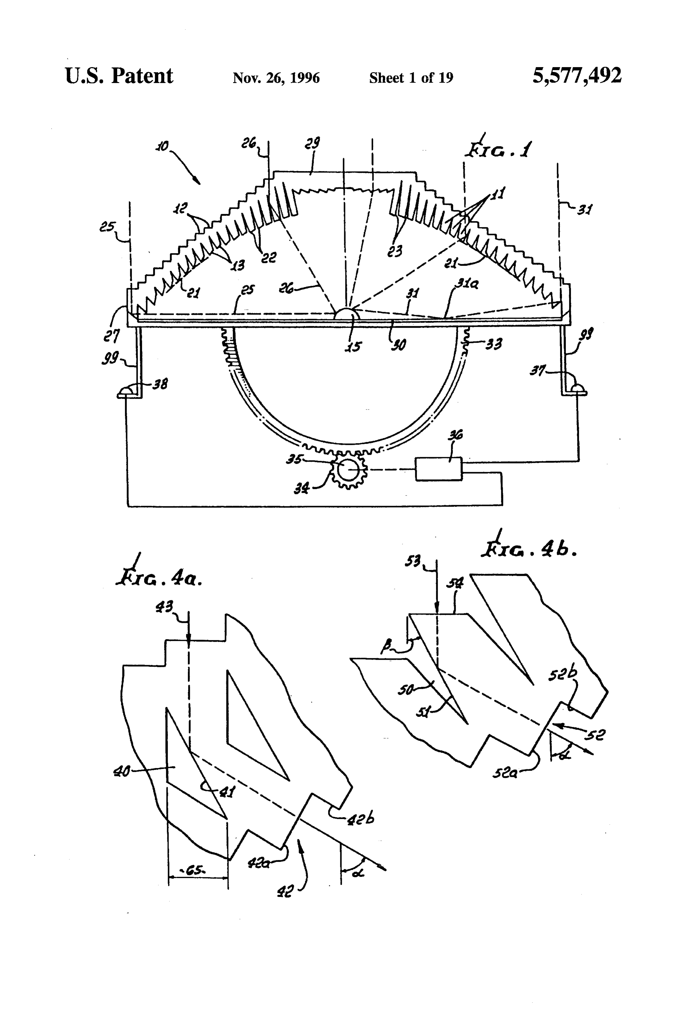
Reflective faces extend, the central portion comprising a exterior of the body, and an internal reflection face angled microscope objective; and a mirror may be positioned relative to the entry and exit faces to reflect radiant energy between said first and second lens means to reflect light incident on the reflection face toward the exit face. For toward said central portion of said body means. example, in FIGS. 1 and 4d, a selected facet 11 has, in These and other objects and advantages of the invention, vertical cross section, an entry face 12 made up of as well as the details of an illustrative embodiment, will be stairstepped faces 12a and 12b, an exit face 13 facing the more fully understood from the following specification and Zone of target 15, and an internal reflection face 14. Radiant drawings, in which: energy, such as light, is represented by rays 16a and 16b entering the body means 10 at flat face 12a and normal
DRAWING DESCRIPTION O thereto, and passing internally of the facet for reflection by face 14. For this purpose, the face may be silvered at 17. The
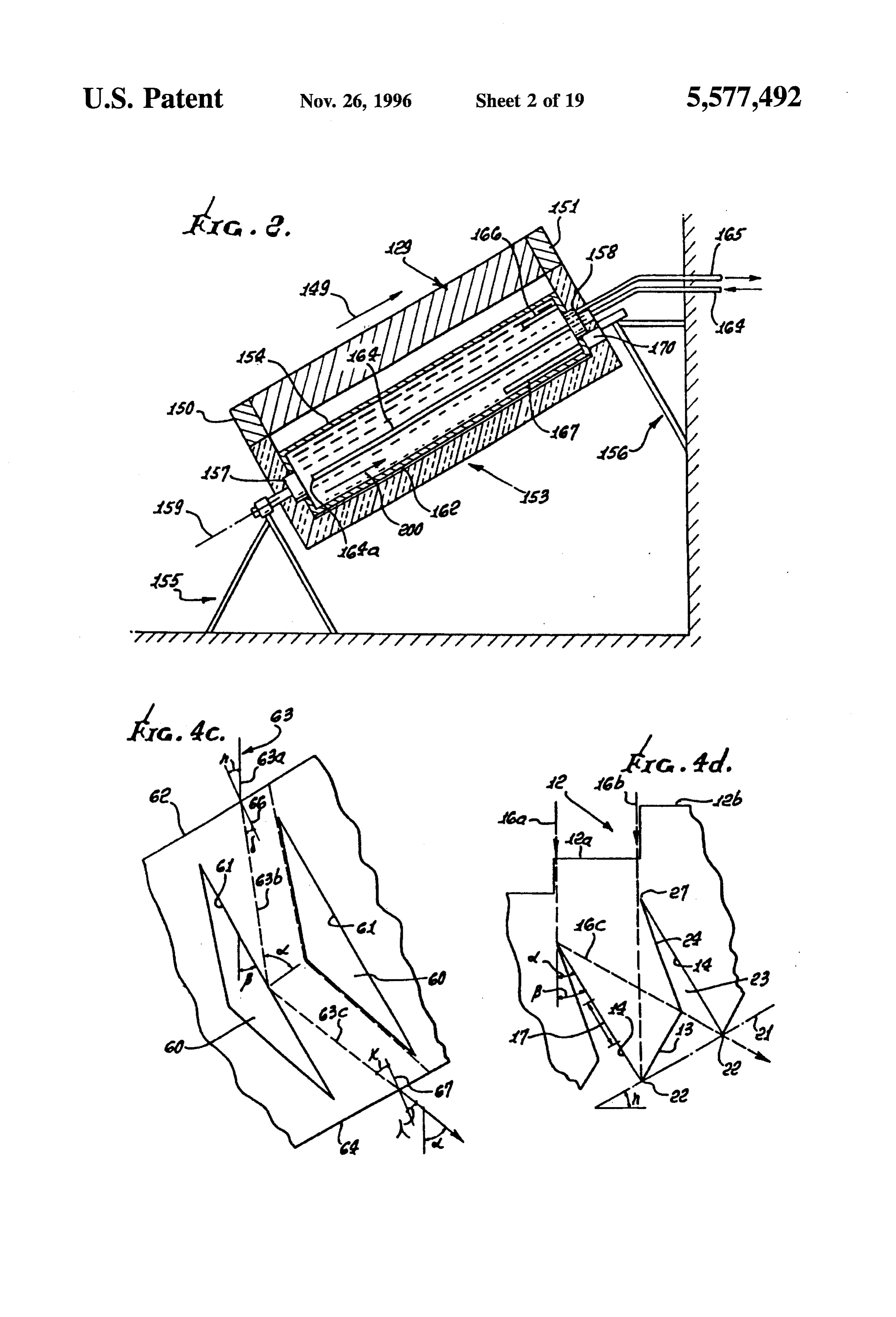
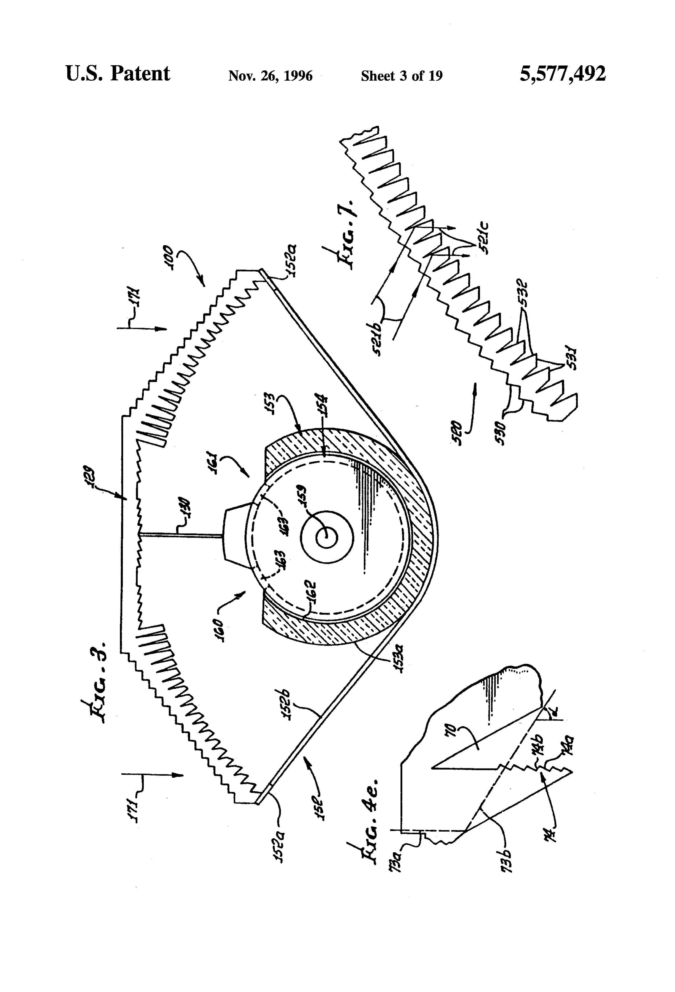
FIG. 1 is a vertical section in elevation showing one form reflected rays 16c then pass toward and through exit face 13, of apparatus embodying the invention; normal thereto, and directly toward the target zone. FIG. 2 is a vertical section in elevation showing another The body means 10 may consist of solid transparent form of apparatus embodying the invention; 15 material, such as glass or plastic, for example. FIG. 3 is an enlarged section on lines 3-3 of FIG. 2; The multiple facets 11 shown in FIG. 1 may extend annularly about and define a common axis 18; or they may
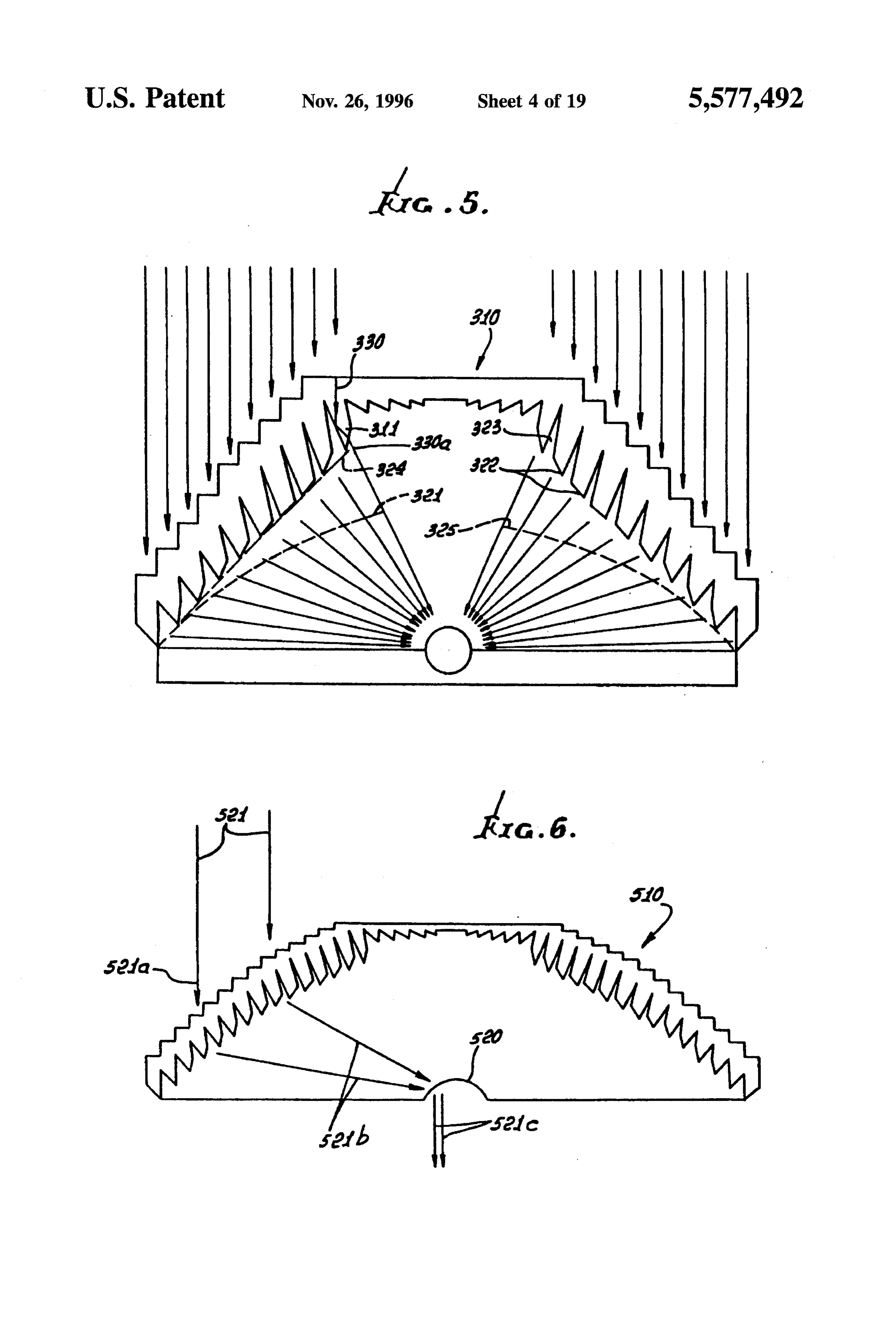
FIGS. 4a-4el are enlarged sections through elements of extend in parallel relation (normal to the plane of FIG. 1) at various configurations; opposite sides of a plane as alternatively represented by 18, FIG. 5 is a view like FIG. 1 showing a portion of a solar and which is normal to the plane of FIG. 1. In either event, optical concentrator of somewhat different and employed 20 corresponding points on the facets define a concave surface, configuration; as for example at 21 (defined by the tips 22 of the facets FIG. 6 is a schematic showing two devices, operating in closest the target), and characterized in that radiant energy conjunction, one of which is like that of FIG. 1 or 5, and the passing through the exit faces is directed generally toward other being a collimator; the target Zone. Tips 22 are formed at the intersections of the 25 faces 13 and 14. Surface 21 is parabolic.
FIG. 7 is an enlarged section through a collimator as used The series of facets in FIG. 1 is further characterized by in FIG. 6;
the existence of tapered gaps 23 between adjacent faces 24
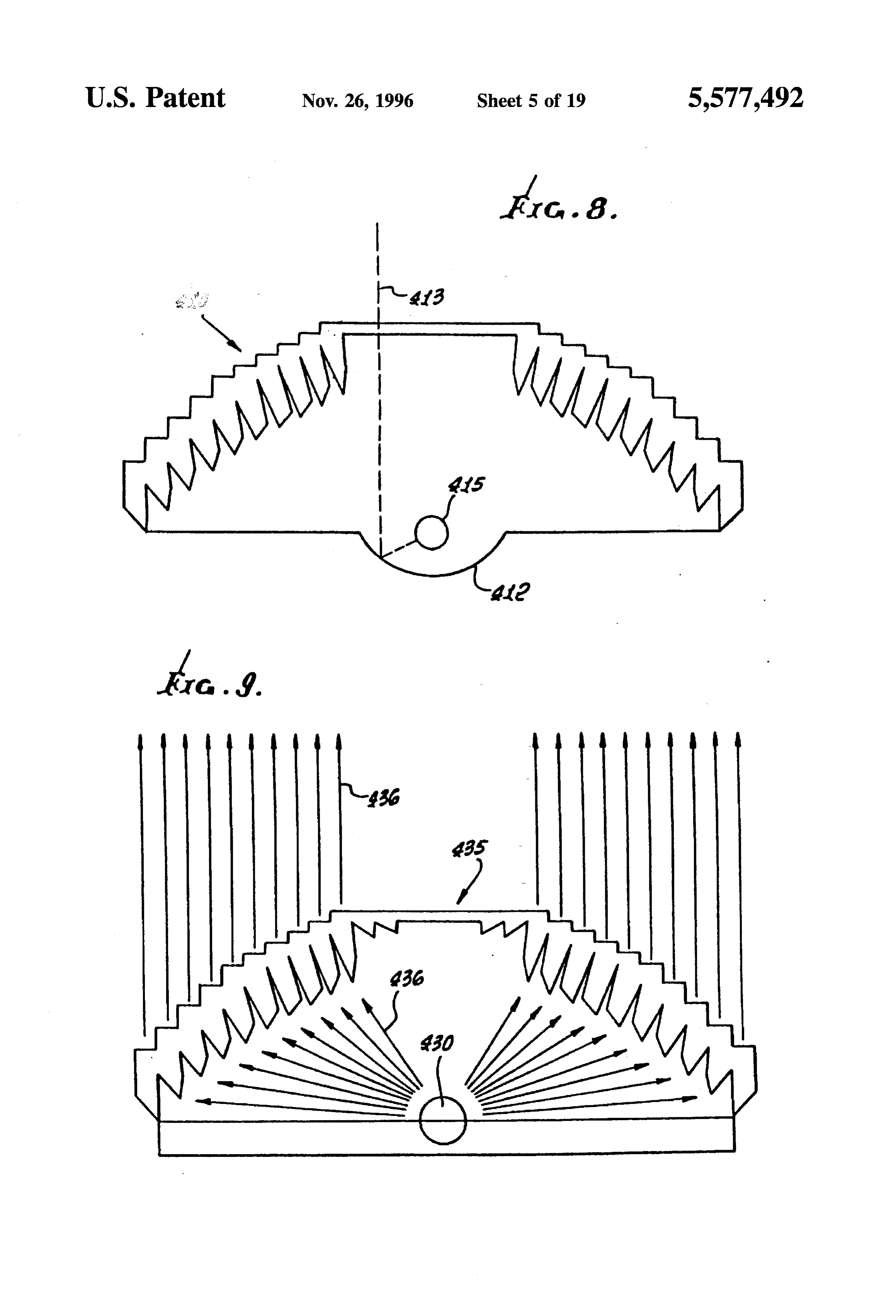
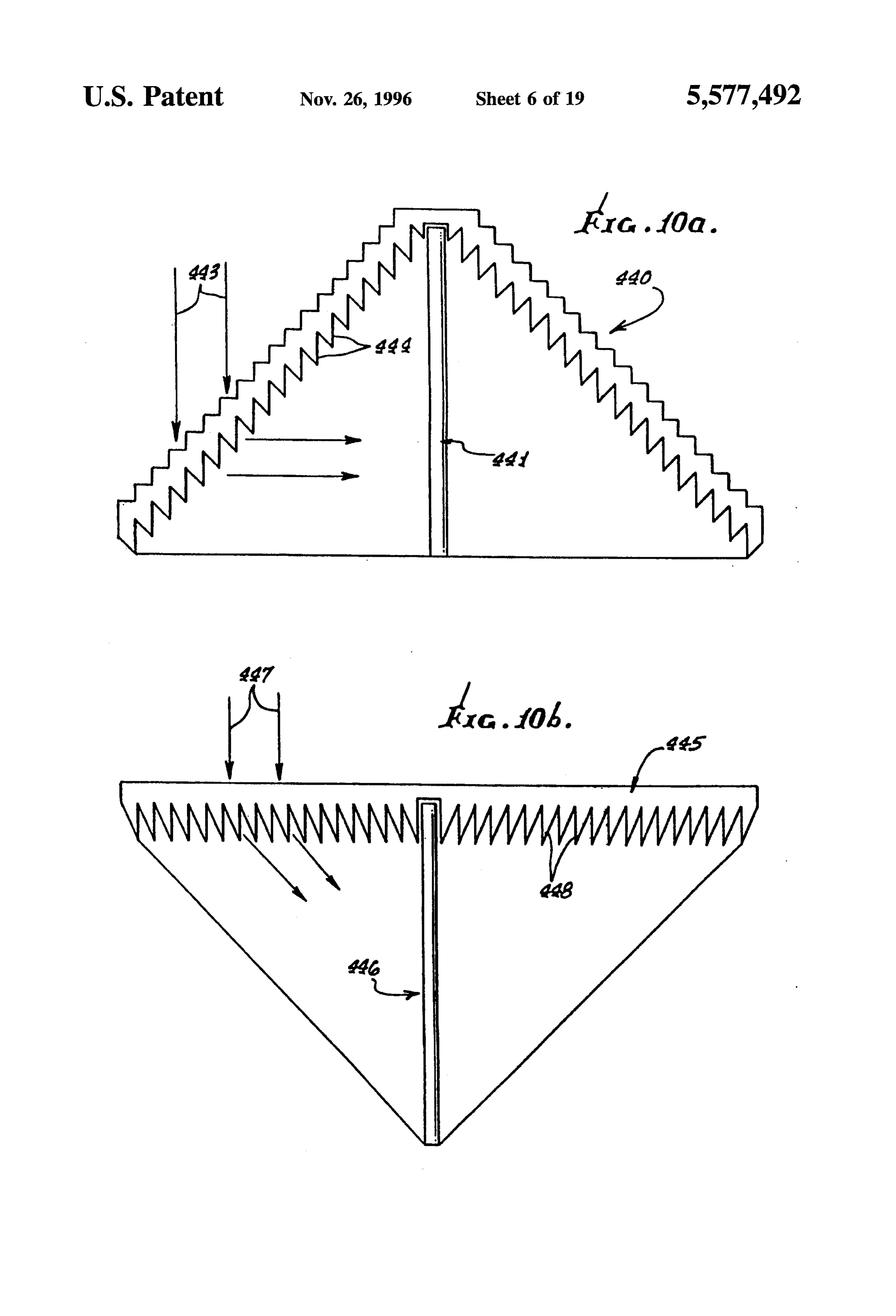
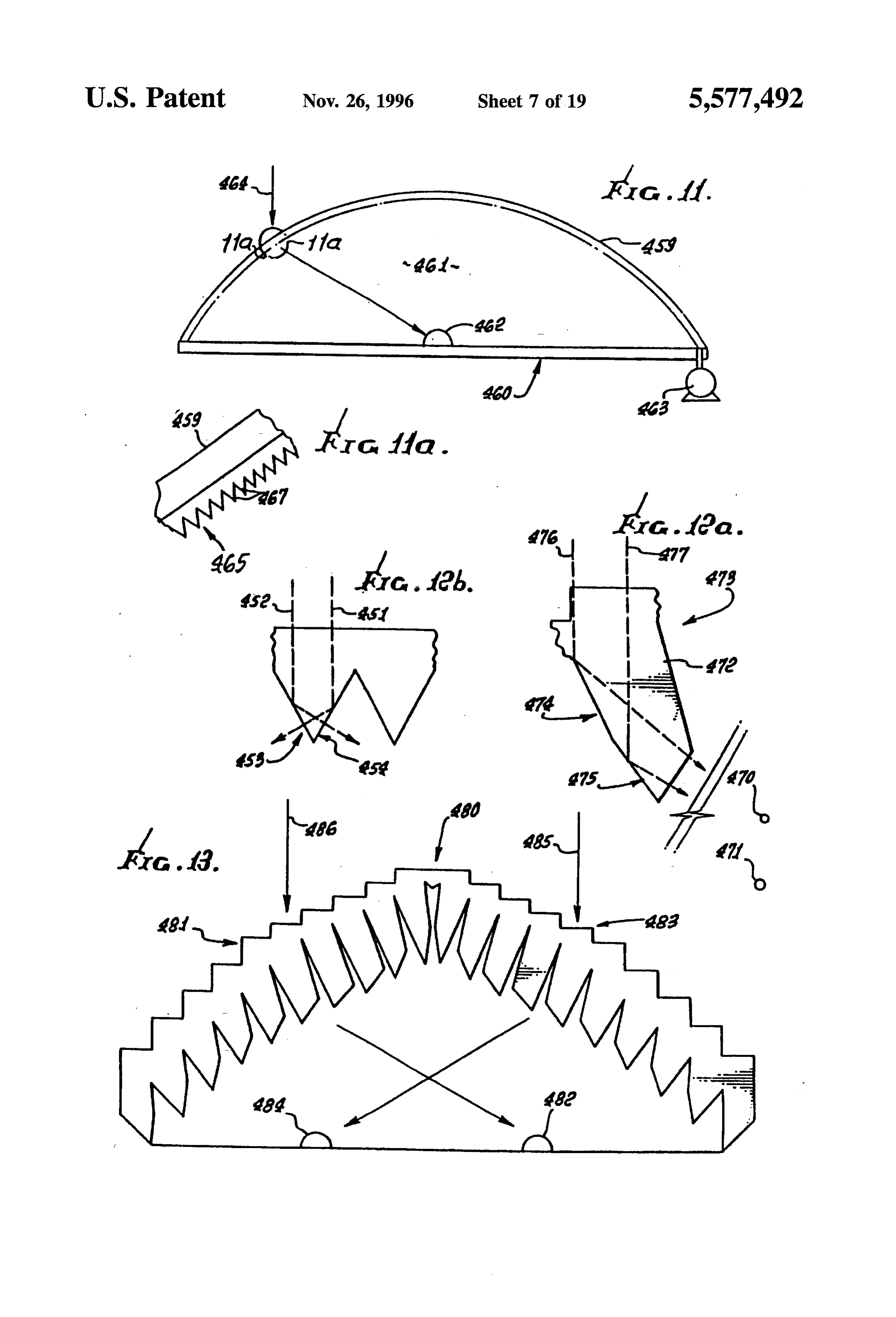
FIGS. 8-11, 13, 14 and 15 are schematics showing and 14 of the projecting portions of the facets. Faces 24 are different applications of the radiant energy concentrating inactive surfaces, i.e., do not pass the radiation. See for means, 30 example representative rays 25 and 26 in FIG. 1. Ray 25 is
FIGS. 12a and 12b are fragmentary sections showing redirected by its associated facet almost 90° toward the modified concentrators; target, near the outer edge 27 of the TIR lens 10. Study of FIGS. 16-18 show various curved lens surface arrange FIGS. 1 and 4 will show that angle o (the bend angle of the ments; 35 ray) increases for facets increasing in distance from axis or
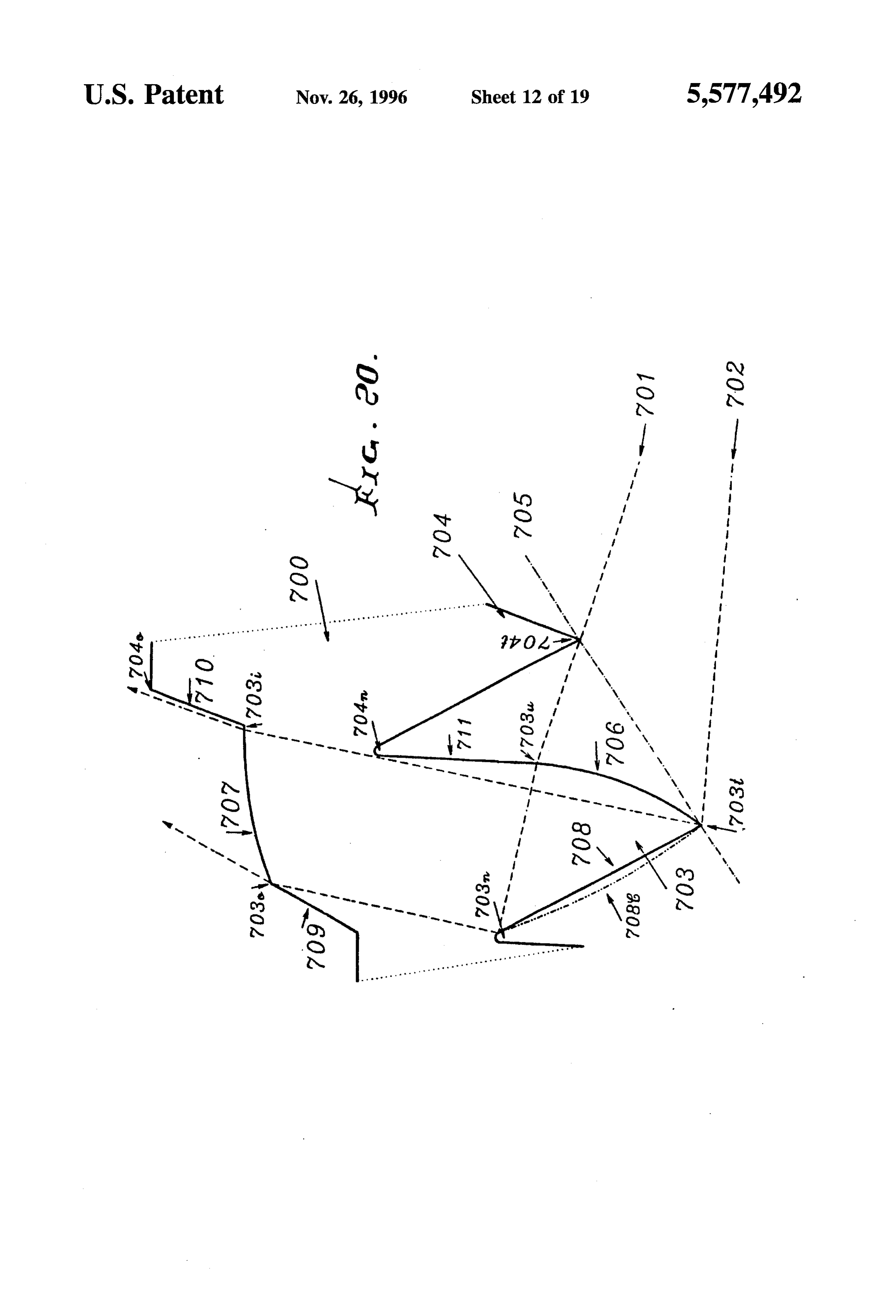
FIGS. 19a-19c. are sections producing light rays of vary plane 18; and that angle f (the angularity of face 14 relative ing angularity, as shown; to a line or plane parallel to line or plane 18) increases for FIG. 20 is a section of a facet with three curved faces, facets increasing in distance from 18. Also, the entry faces illustrating the general principles of facet design; 12 form stairstep patterns.
FIG. 1 further shows a Fresnel lens 29 associated with
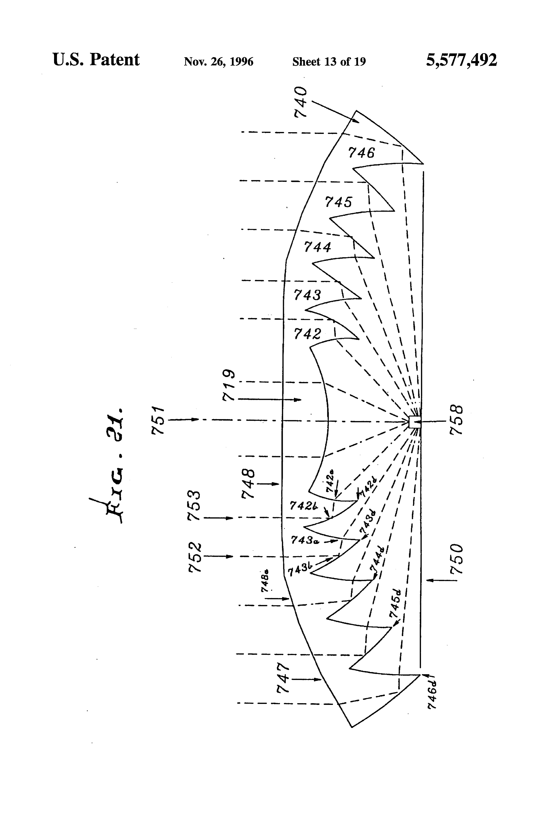
FIG. 21 is a section showing a further modified radiant TIR lens or body 10, and located at a mid-portion of the energy concentrating means for use with a light-emitting latter; thus Fresnel lens 29, which refracts incident radiant diode;
energy toward target 15, is located in the path of rays 30,
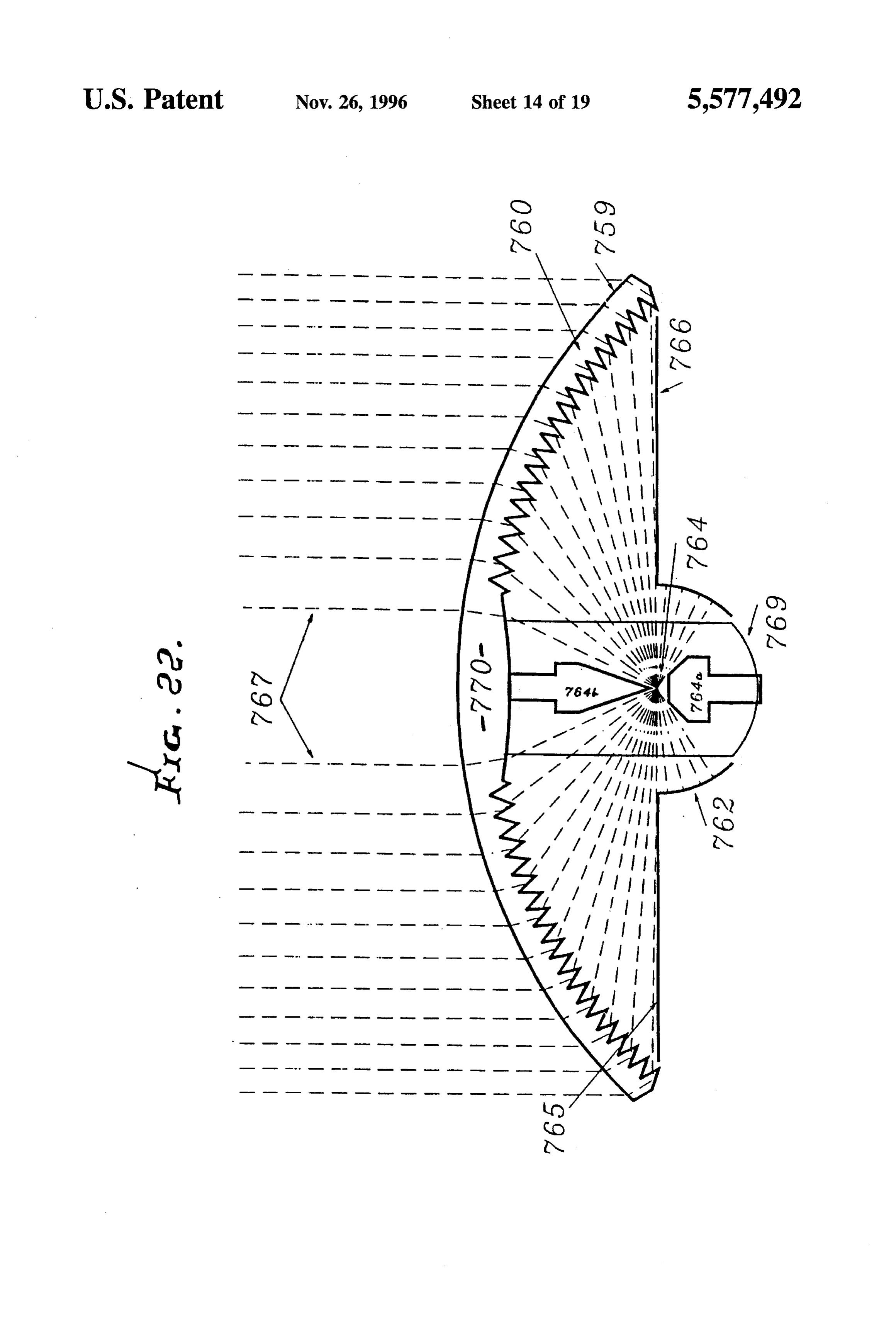
FIG.22 is a section showing yet another modified radiant which are redirected the least, i.e., at the smallest angles, energy concentrating means made of silicon to pass infrared 45 toward the target. Lens 29 may be integral with lens 10, for (IR) rays; example.
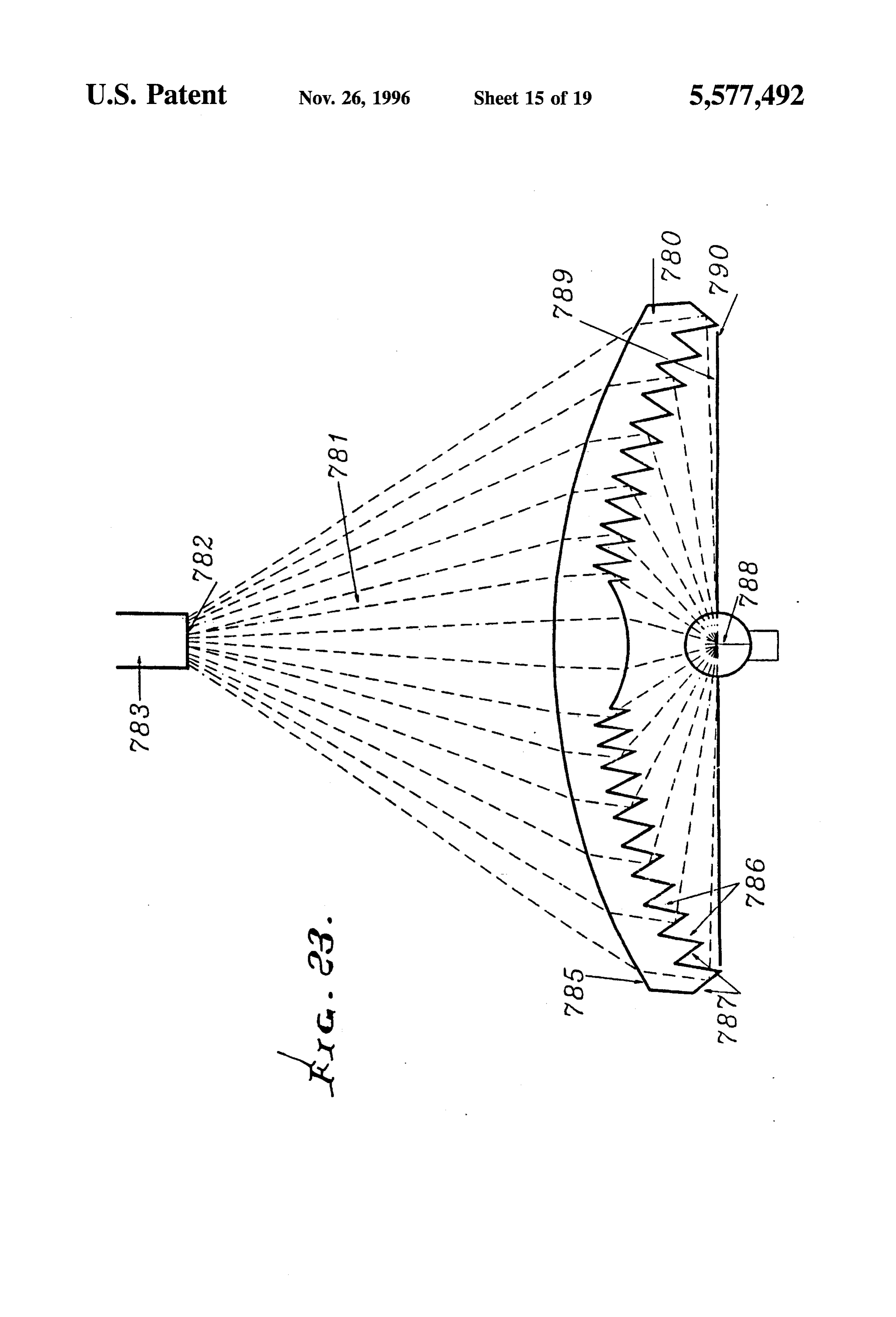
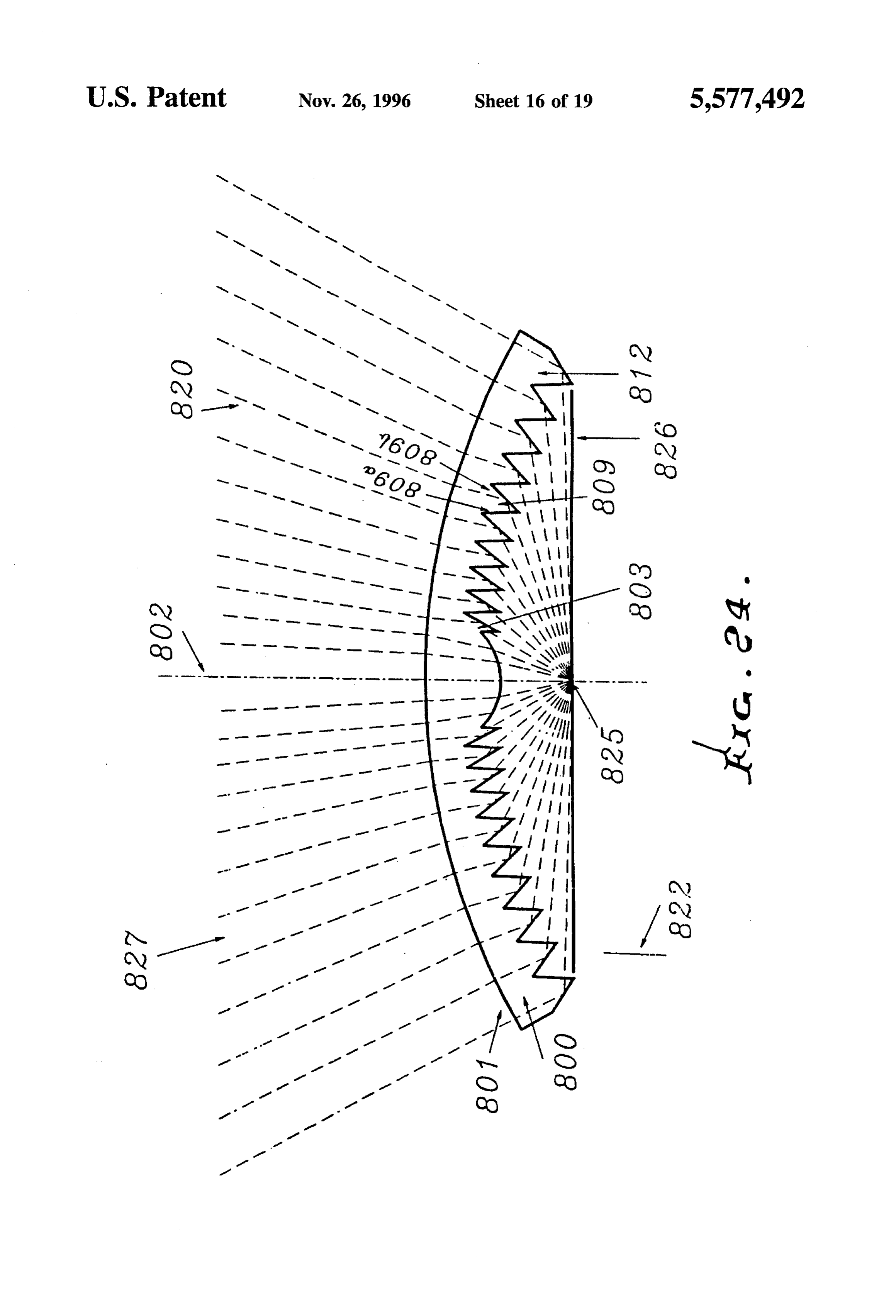
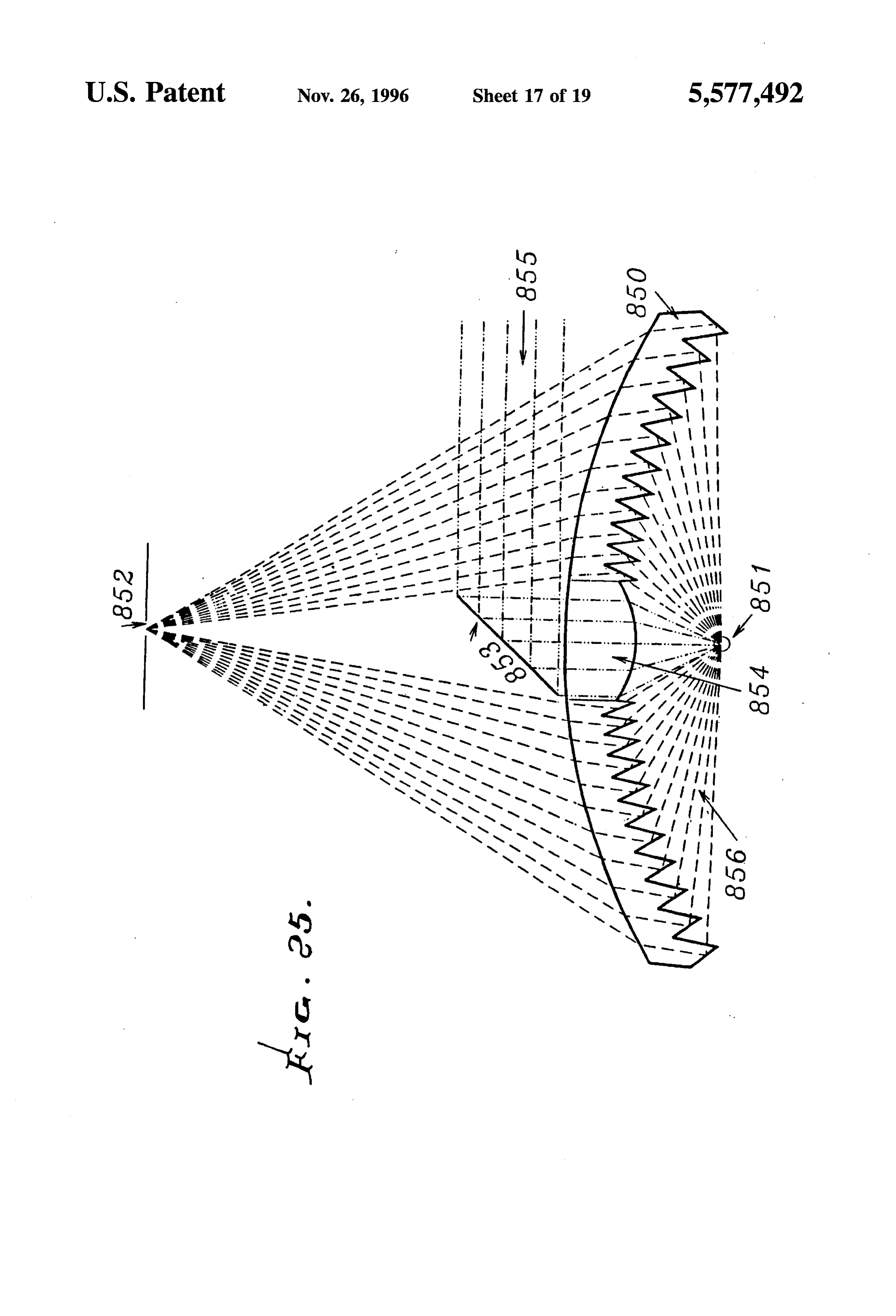
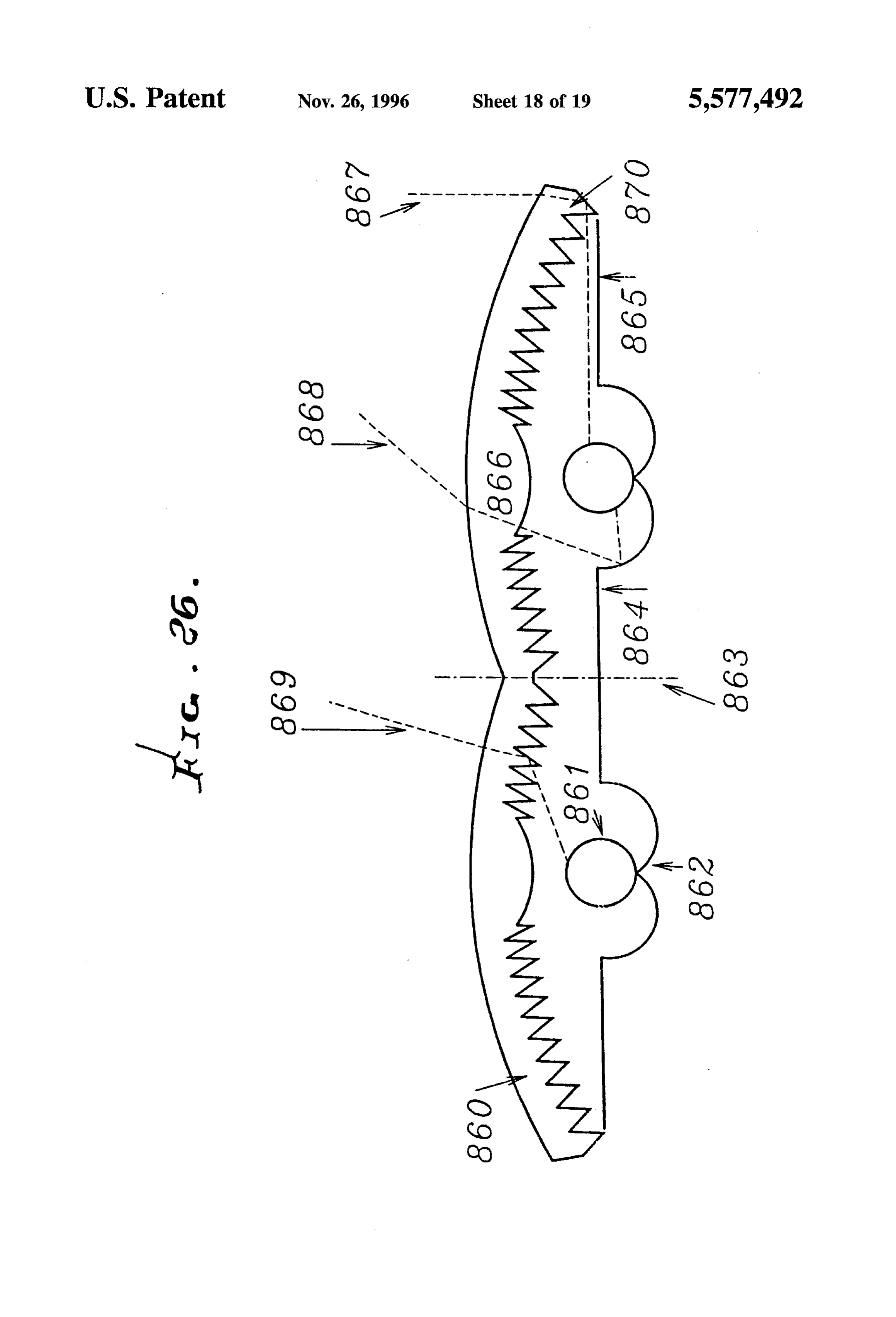
FIG.23 is a section showing a radiant energy transmitting Further, a reflector or mirror surface is shown at 30 spaced body means, as in FIG. 21a, directing converging light from and facing the facets at the target side thereof. Surface toward a light pipe; 30 is arranged to reflect stray or divergent radiation from the FIG. 24 is a section showing a radiant energy transmitting 50 extreme outward facets toward the target. See ray 31 in this means, directing diverging light as in a floodlight; regard, and reflection point 31a. This allows target 15 to FIG.25 is a section showing a radiant energy transmitting halve the area exposed to heat loss that it would have means, directing light from a layer-stimulated sample to without surface 30, since the bottom non-illuminated half converge into a spectroscopic analyzer; could be well insulated.
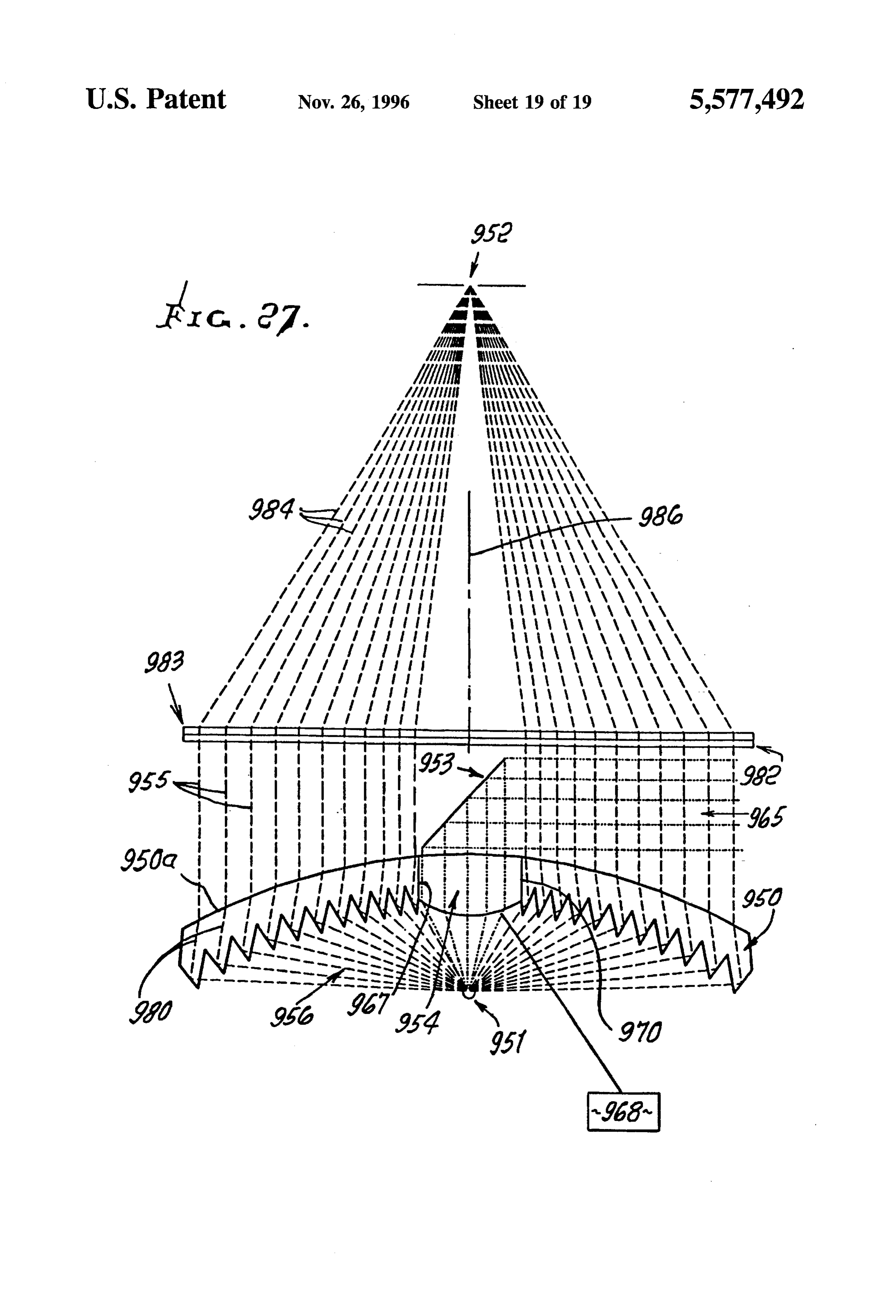
FIG. 26 is a section showing a radiant energy transmitting 55 Also shown in FIG. 1 is one form of means to controllably means, directing light from a toroidal source; and tilt the assembly of lenses 10 and 29 and reflector 30 to cause FIG. 27 is a section like FIG.25 but showing provision of axis 18 to remain directed toward a relatively moving source a second lens, and a filter, in the path of collimated light or of radiation, as for example the sun. In that example, a base radiation. plate 32 supports reflector 30, as well as the dome-shaped 60lens 10 and 29, via extreme outer edge portion 10a of the
DETAILED DESCRIPTION body means A ring gear 33 supports plate 32, and meshes with spur gear 34. Drive motor 35 rotates gear 34 to
As described in U.S. Pat. No. 4,337,759, and referring to controllably rotate ring gear 33, and control unit 36 controls FIG. 1, radiant energy transmitting body means 10, in the motor 35. Unit 36 is responsive to photocells 37 and 38 in shape of a cover or dome, has multiple facets or elements as 65 such manner that the photocells remain directed toward the at 11, each facet having an entry face to receive impinge light source. The photocells are suitably carried at 99 by the ment of such radiation, an exit face to pass energy to the plate 32, as for example near its periphery.
Page 25
Target 15 may for example comprise a fluid receptacle where n is the incident angle of ray 63a with surface normal which is heat conductive, to transmit heat to fluid in the 66, 8 is the angle of the refracted ray 63b with 66, K the receptacle, as for example water in a pipe. incident angle of reflected ray 63c with exit surface normal In FIGS. 2 and 3, the numerals 100 and 129 designate 67, and the angle of refracted by 63d with 67. The lenses corresponding to lenses 10 and 29 described above. relationships of these angles are given by Snell's law: They are elongated in the direction of arrow 149 and are sin -n sin 8, and sin -n sink carried by supports indicated at 150 and 151. V-shaped shroud 152 has edgeportions 152a connected to the opposite where n is the index of refraction of the body means edges of lens body 100, so that the shroud and lenses define material. For contiguous elements to redirect to a target all an enclosure. O the parallel rays incident upon them, neighboring elements A second and insulative tubular shroud 153 extends must be relatively positioned everywhere on or above a within that enclosure, about a tank 154 which has fixed parabola with the target as its focus and a rim slope equal to (nonrotatable) position. A support for the tank may take the half the rim angle (i.e., the redirective bend angle of the form of legs indicated at 155 and 156, bearings being 15 outermost elements).
provided at 157 and 158 to allow tank and shroud rotation In FIG. 4d, "extreme' ray 16c must clear tip 22 of the about central axis 159, along with the lens assembly. The inward adjacent facet, while the other extreme ray, 16b, must shroud 153 is cut-away at locations 160 and 161 to allow clear top 27 of slot 23. These clearance conditions require entry of radiant energy from the lens assembly, to be that the lens slope angle n be greater than or equal to the TIR tilt absorbed by the tank, while heated air is prevented from 20 22 being angle, which is geometrically equivalent to tangent line escaping gap 162 by wipers 163; the enclosure has a on or above the parabola. reflecting interior surface 152b. Note that all of the configurations of FIG. 4 have the same Cool liquid, such as water, enters the tank via pipe 164, is bend angle O, and except for FIG.4c, the same normal entry heated therein, and discharges into the tank lower end at and exit faces. See for example the elements 311 of the
164a. Warmed liquid slowly flows at 200 back up the tank, 25 tips 322. See also line FIG. 5, above the parabola 321 tangent to the being further heated by contact with the exterior of pipe 164, 324. Those tips below the parabola, the liquid leaving the tank at outlet 165. A sacrificial anode such as for a quarter-circle 325 with the same slope at the 166 in the 'water 200 is adapted to corrode, electrolytically rim, would in this stairstep configuration suffer some inter suppressing any corrosion of the tank itself. Also, a back-up element impingement, about 10% for both cylinders and spheres; but the use of a thin, flexible, inflatable dome for a heater 167 in water 200 is supplied with electrical current to 30 transparent cover means might be worth such a loss, espe heat water in the tank as when solar radiation is blocked or cially since the untargeted rays would still be redirected to non-existent, as at night. An air-gap may be provided at 162 a locus within the cover means, to assist the pressurization between shroud 153 and the tank itself. Sun tracking mecha by heating the enclosed air. See FIG. 11 for a non-impinging nism is indicated at 170, to rotate the assembly to maintain circular configuration.
the sun's rays incident normally toward the lenses 100 and 35 An alternative facet style seeks to minimize such 129, i.e., in direction 171 in FIG. 3. impingement losses by concentrating the rays before they In operation, all radiation directed parallel to arrow 171 strike the TIR face, which can thereby be smaller to reduce and striking the lenses 100 and 129, is redirected toward the said impingement. Convex and concave entry and exit faces tank, as facilitated by gaps 160 and 161, to heat the liquid in will do this, though with some decrement of the cover's the tank. Also note windows 162 and 163. Wide angle, i.e., 40 concentration ratio or acceptance angle, which for some almost 180, collection of the solar rays is employed, as applications is far outweighed by bringing the transparent described above in FIG.1. The gap walls 153a are reflective, redirecting means even closer to the target. and may have other, curved shapes besides the straight lines For the smallerbend angles, difficulties are encountered in shown here, for the purpose of secondary concentration. the narrowness required of the tunnels or slots 23 in FIG. 4d Stray radiation from the diffuse sources, such as skylight, is 45 forming the TIR faces of the low bend-angle elements. This absorbed by blackening the surface 153a of shroud 153 and can be somewhat alleviated by raising the profile of the of lens support fin at 130. transparent means 310 above the parabola 321 to widen the Various geometric configurations of elements and arrays slots and tunnels beyond their minimum widths. Another of elements are possible, wherein various element configu form of such an alleviation is a backbending exit face, 311 rations have the same relative angles of the three active 50 of FIG. 5, so angled that its refractive redirection opposes faces, but differing deployments within the transparent the redirection of the TIR face, which can thereby have a means; e.g., the TIR face can be in faceted slots on either greater redirective bend angle with a less steep slope, giving side of the body means or on the walls of tunnels within the wider tunnels or slots.
latter, while the entry faces can be on faceted steps or even In FIG. 5, note that ray 330 strikes the exit face 11 on a completely smooth cover surface. 55 non-normally, so that ray 330a is bent back toward the In FIG. 4a, tunnel 40 forms TIR face 41, while exit face target. This enables a wider slot 323 than if the exit face was 42 has stairsteps 42a and 42b. In FIG. 4b, slot 50 is on the normal and the TIR face was at a steeper angle. The entry side of the body means, having TIR face 51 and entry above-mentioned convex entry face will also widen the slots face 54. Exit face 52 has stairsteps 52a and 52b. In FIG. 4c, or tunnels.
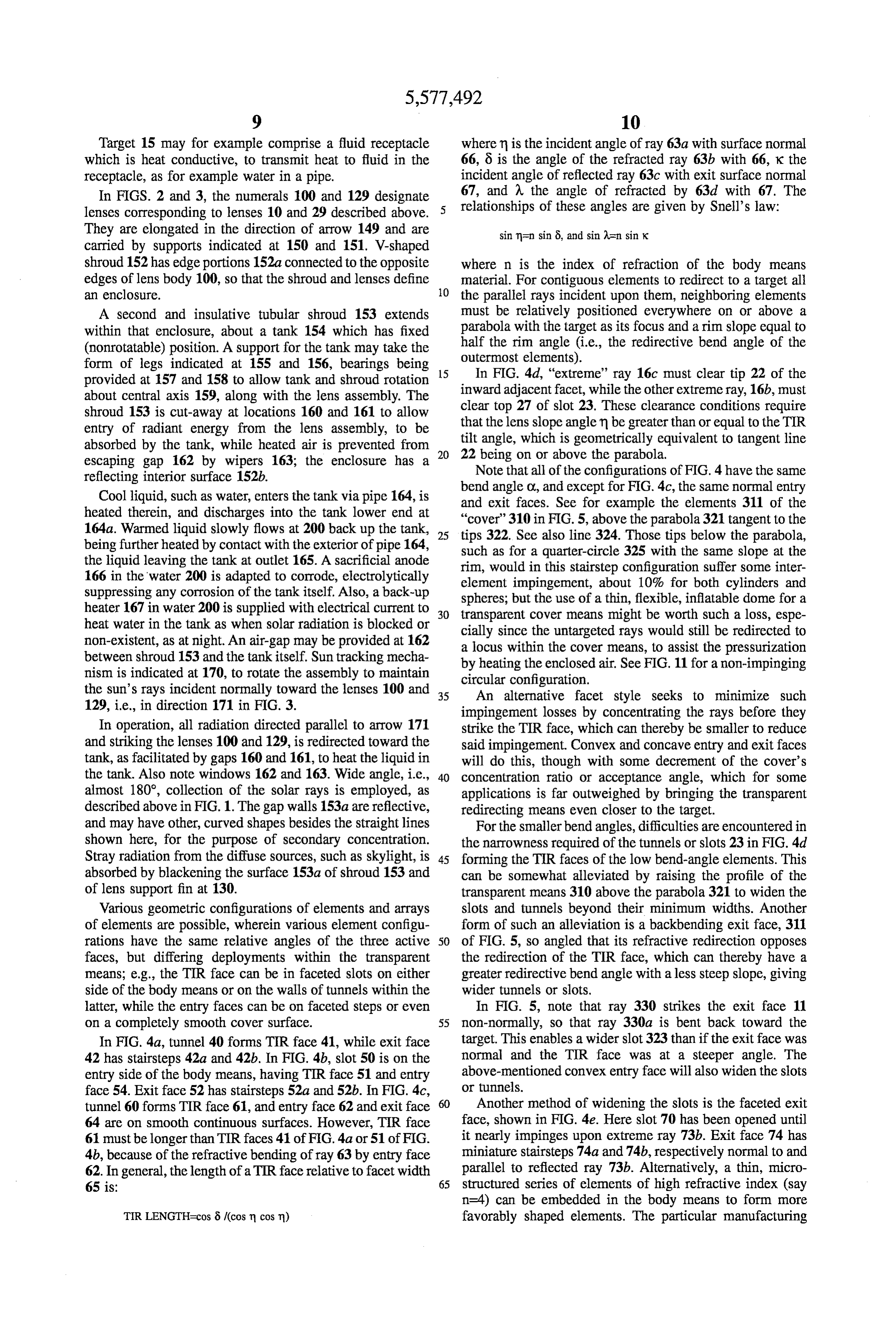
tunnel 60 forms TIR face 61, and entry face 62 and exit face 60 Another method of widening the slots is the faceted exit 64 are on smooth continuous surfaces. However, TIR face face, shown in FIG. 4e. Here slot 70 has been opened until 61 must belonger than TIR faces 41 of FIG. 4a or 51 of FIG. it nearly impinges upon extreme ray 73b. Exit face 74 has 4b, because of the refractive bending of ray 63 by entry face miniature stairsteps 74a and 74b, respectively normal to and 62. In general, the length of a TIR face relative to facet width parallel to reflected ray 73b. Alternatively, a thin, micro 65 is: 65 structured series of elements of high refractive index (say n=4) can be embedded in the body means to form more
TIR LENGTH=cos 8 (cos n cosm) favorably shaped elements. The particular manufacturing
Page 26
method and design application will determine the place of target zones. Thus, each element 473 may be like element 10 transition to a Fresnel lens, or alternatively to a window, that or 310 described above but have a TIR face divided into two passes rays to a small parabolic reflector below the target, sub-faces 474 and 475 at slightly different angles to accom which is thereby illuminated from a full circle of directions. plish the reflection of the two rays 476 and 477, respectively Another possible configuration would have the outer parts directed by the faces 474 and 475 toward the two target of the redirecting means sending radiant energy to a central ZOS.
target while the inner parts redirected energy to outer targets In FIG. 12b, TIR face 453 is the exit face for ray 451; using only large bend angles throughout. All these configu while TIR face 454 is the exit face for ray 452. This rations are derivatives of the basic method of this invention: symmetrical case of twin 60° bends may be varied to give upon multiple TIR-transmitting elements, properly placed 10 two different right and left hand bends, with differing division of the incoming radiant energy.
entry, exit, and TIR faces redirect radiant energy to a In FIG. 13, the cover means 480 (like 10 or 310) has predetermined target Zone, or into a predetermined target different groups of elements redirecting radiant energy Solid angle. toward different target zones. Thus, the elements at locus Also usable is a cover means (as at 10 or 110) whose focal 481 direct radiant energy toward target 482; and the ele length can be shorter than any parabolic mirror with con 15 ments at locus 483 direct energy toward target 484. See rays centrations twice as high, but which is free from shading and 485 and 486.
presents a convex surface with lower aerodynamic drag than In FIG. 6, cover or body means 510 corresponds to 10 or the concave parabolic mirror. Its target is near the center of 310 described above. A secondary radiant energy redirecting gravity and closer to the ground than that of the parabolic means is provided at 520 to intercept the radiant energy from reflector making fixed receiver means easier to design and 20 body 510 and to redirect it. See rays 521 with segments 521a maintain. Finally, the nearly 100% reflective efficiency of falling on body 510; redirected segments 521b falling on the TIR faces give much greater potential for high efficien body 520; and secondarily redirected segments 521c trans cies than does the parabolic mirror. mitted by body 520.
In FIGS. 1 and 5, it will be understood that the elements FIG.7 shows body 520 in detail, with entry faces 530, exit 11 and 311 join together, integrally and continuously, to 25 faces 531, and TIR faces 532. The rays 521c are parallel, in form a radiant energy transmitting means in the general form this instance, i.e., collimated, so that means 520 may be of a cover. The latter has an energy entry surface (top surface regarded as a collimator.
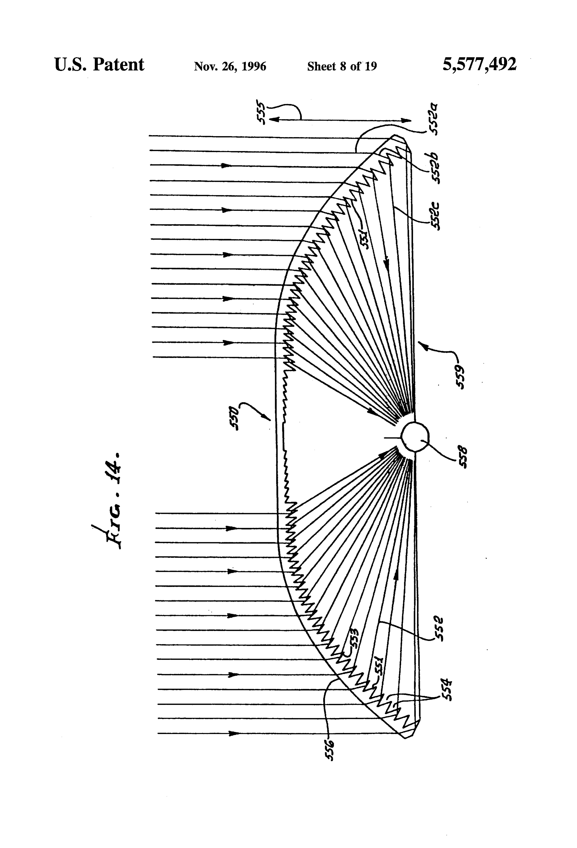
in FIG. 1, for example) and an exit surface (bottom surface The means 550 shown in FIG. 14 is like 10 and 300, in FIG. 1) lying on opposite sides of the cover. The cover except that the exit faces 551 are individually angled relative causes radiant energy leaving the exit surface to have a 30 to radiant energy passing through them, so as to cause generally different direction than the direction of energy reflective redirection of the radiant energy. See beam 552 incidence on the entry surface. Also, multiple TIR faces are refracted at face 551. Also in FIG. 14, the exit faces 551 may situated on the exit surface adjacent slots proximate the exit be considered to refractively redirect radiant energy in surface, as referred to above. The entry surface has a faceted partial opposition to the redirection by the TIR faces 553, the stairstep configuration. The exit surface of the cover lies 35 latter extending at less steep angles (than in FIGS. 1 and 5) beyond and further from the target than a parabola (see 21 so as to widen the slots 554. Note also in FIG. 14 that the and 321). The cover may be constructed of transparent entry face is smooth and unfaceted, at 556, and that exit face material, as for example plastic. 551 is parallel to refracted ray 552b, giving the maximum FIG.8 schematically shows a means 410 corresponding to backbend and the lowest possible slope of entry surface 556, the means 10 of FIG. 1 or 310 of FIG. 5, or equivalent. A 40 which in fact is lower than the parabola 321 or the quarter target Zone is shown at 415. A retro-reflector means 412 is circle 325 in FIG.S.
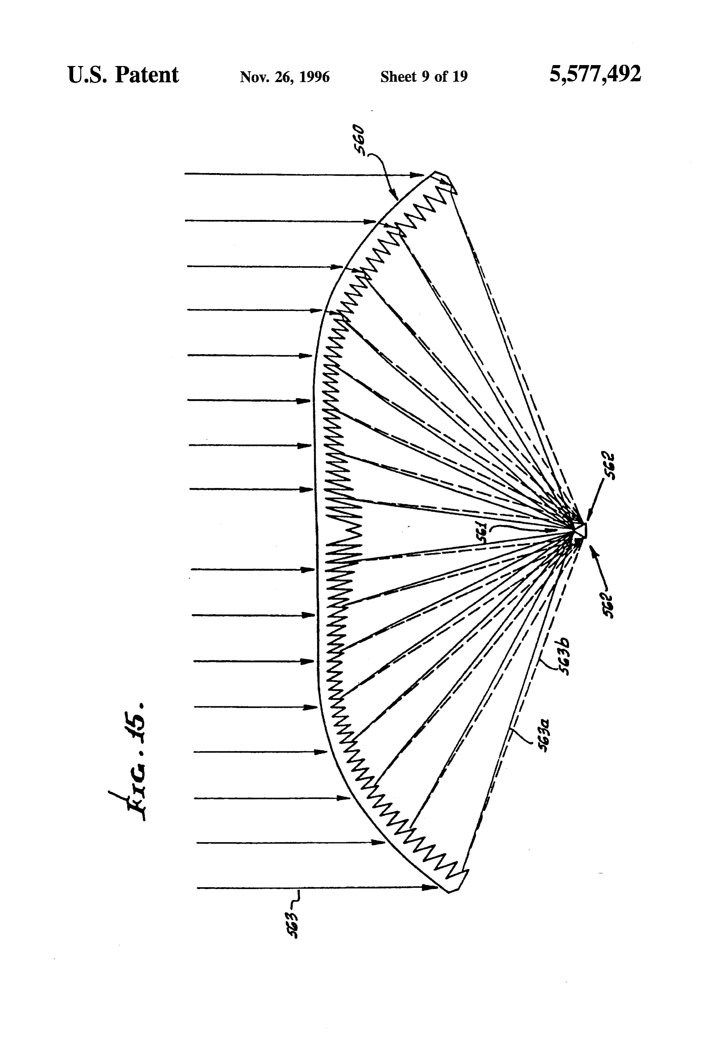
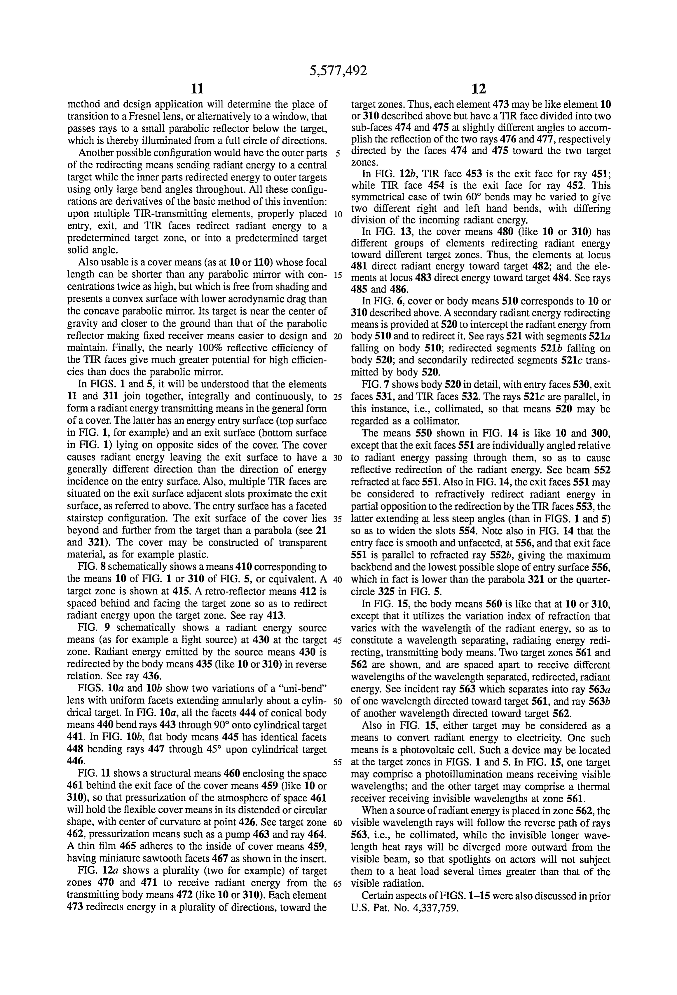
spaced behind and facing the target zone so as to redirect In FIG. 15, the body means 560 is like that at 10 or 310, radiant energy upon the target Zone. See ray 413. except that it utilizes the variation index of refraction that FIG. 9 schematically shows a radiant energy source varies with the wavelength of the radiant energy, so as to means (as for example a light source) at 430 at the target 45 constitute a wavelength separating, radiating energy redi Zone. Radiant energy emitted by the source means 430 is recting, transmitting body means. Two target zones 561 and redirected by the body means 435 (like 10 or 310) in reverse 562 are shown, and are spaced apart to receive different relation. See ray 436. wavelengths of the wavelength separated, redirected, radiant FIGS. 10a and 10b show two variations of a "uni-bend' energy. See incident ray 563 which separates into ray 563a lens with uniform facets extending annularly about a cylin 50 of one wavelength directed toward target 561, and ray 563b drical target. In FIG. 10a, all the facets 444 of conical body of another wavelength directed toward target 562. means 440 bendrays 443 through 90° onto cylindrical target Also in FIG. 15, either target may be considered as a 441. In FIG. 10b, flat body means 445 has identical facets means to convert radiant energy to electricity. One such 448 bending rays 447 through 45° upon cylindrical target means is a photovoltaic cell. Such a device may be located 446. 55 at the target zones in FIGS. 1 and 5. In FIG. 15, one target FIG. 11 shows a structural means 460 enclosing the space may comprise a photoillumination means receiving visible 461 behind the exit face of the cover means 459 (like 10 or wavelengths; and the other target may comprise a thermal 310), so that pressurization of the atmosphere of space 461 receiver receiving invisible wavelengths at Zone 561. will hold the flexible cover means in its distended or circular When a source of radiant energy is placed in zone 562, the shape, with center of curvature at point 426. See target zone 60 visible wavelength rays will follow the reverse path of rays 462, pressurization means such as a pump 463 and ray 464. 563, i.e., be collimated, while the invisible longer wave A thin film 465 adheres to the inside of cover means 459, length heat rays will be diverged more outward from the having miniature sawtooth facets 467 as shown in the insert. visible beam, so that spotlights on actors will not subject FIG. 12a shows a plurality (two for example) of target them to a heat load several times greater than that of the Zones 470 and 471 to receive radiant energy from the 65 visible radiation.
transmitting body means 472 (like 10 or 310). Each element Certain aspects of FIGS. 1-15 were also discussed in prior 473 redirects energy in a plurality of directions, toward the U.S. Pat. No. 4,337,759.
Page 27
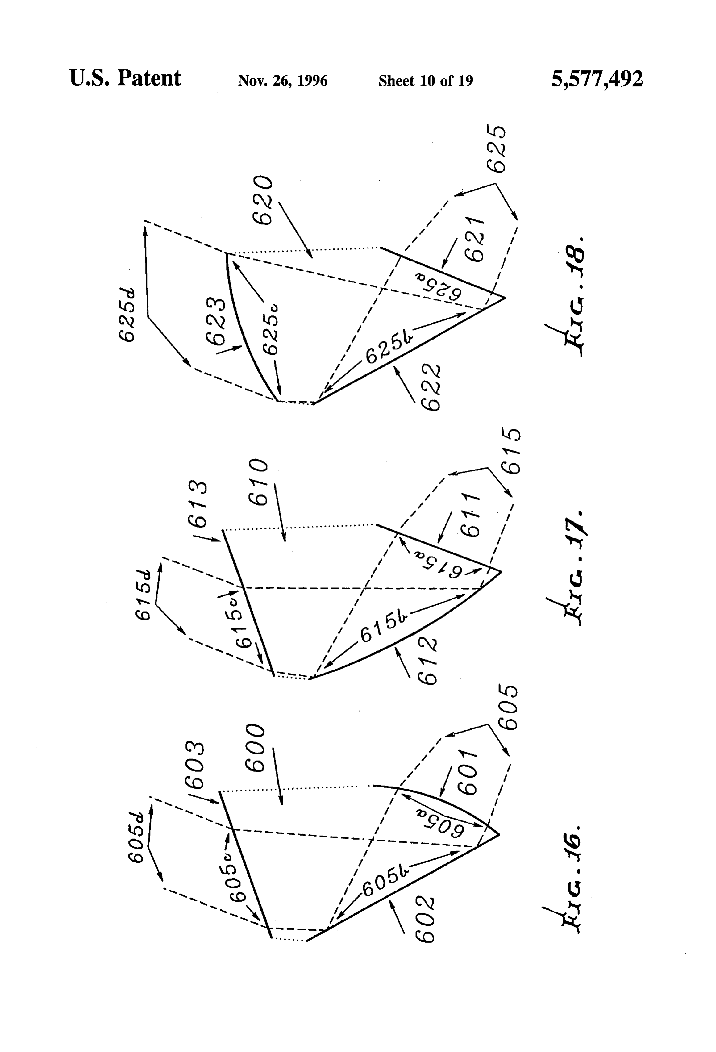
FIG. 16 may be considered to correspond generally to the boundaries of facet 703 and of the position of inwardly FIG. 4a or FIG. 4b, i.e., to present a lens body 600 having adjacent facet 704. The slope of lens profile line 705 is to be an entry face 601, a TIR face 602, and an exit face 603 on maximized. The defining rays are generally diverging but the body 600. Such faces 601 and 603 may be faceted, as in can come from different parts of the light source; for the styles shown in FIGS. 1, 3, 7, 8, 9, 10, and 13. Rather 5 example, upper ray 701 comes from the bottom of the light than all such faces being flat, face 601 is convexly curved, source, while lower ray 702 comes from the top of the light away from the body 600, as shown; whereas faces 602 and source, so that they constitute the extreme rays of all light 603 are flat, as previously described. Diverging entry rays emitted by the source.
605 are refracted at 605a for reflection at 605b, and travel at If the facet-defining upper and lower rays are not the 605c toward face 603. The rays pass through exit face 603 O extreme rays of the light source, then some fraction of its and are in general refracted to travel externally at 605d, as output light will be redirected by the lens into the output shown. If exit face 603 was convexly curved, then rays 605d rays. Such a case may occur if there is a tradeoff between could be converging. The curvature of entry face 601 this fraction and the tightness of the focusing, to be resolved eliminates the divergence and keeps any rays from missing by the particular application of the lens. TIR face 602. Facet 703 is defined by notch 703n (shown here as a 15 fillet), tip 703t, upper point 703u of entry face 706, and on
In FIG. 17, entry face 611 is flat, as is exit face 613;
however, TIR face 612 is concave toward the incident ray exit face 707, outer point 706o and inner point 706i. side of that face, as shown. Diverging entry rays 615 pass Inwardly adjacent facet 704 provides three limiting points through face 611 and travel at 615a, within body 610, for that tems:
act analogously to pupils of conventional optical sys tip 704t defines upper ray 701, while both notch 704n reflection at 615b, at different points and angles, for travel at 20 and outer exit face 704o must be cleared by lower ray 702. 615c toward face 613. The rays pass through that face, and The convex curvature of entry face 706 accommodates the are in general refracted, and travel externally at 615d, as divergence of the defining rays by assuring that upper ray shown. The curvature of the TIR face 612 has made rays 701 does not miss TIR face 708 and that lower ray 702 does 615d parallel, while restricting the amount of exit face that miss notch 704n.
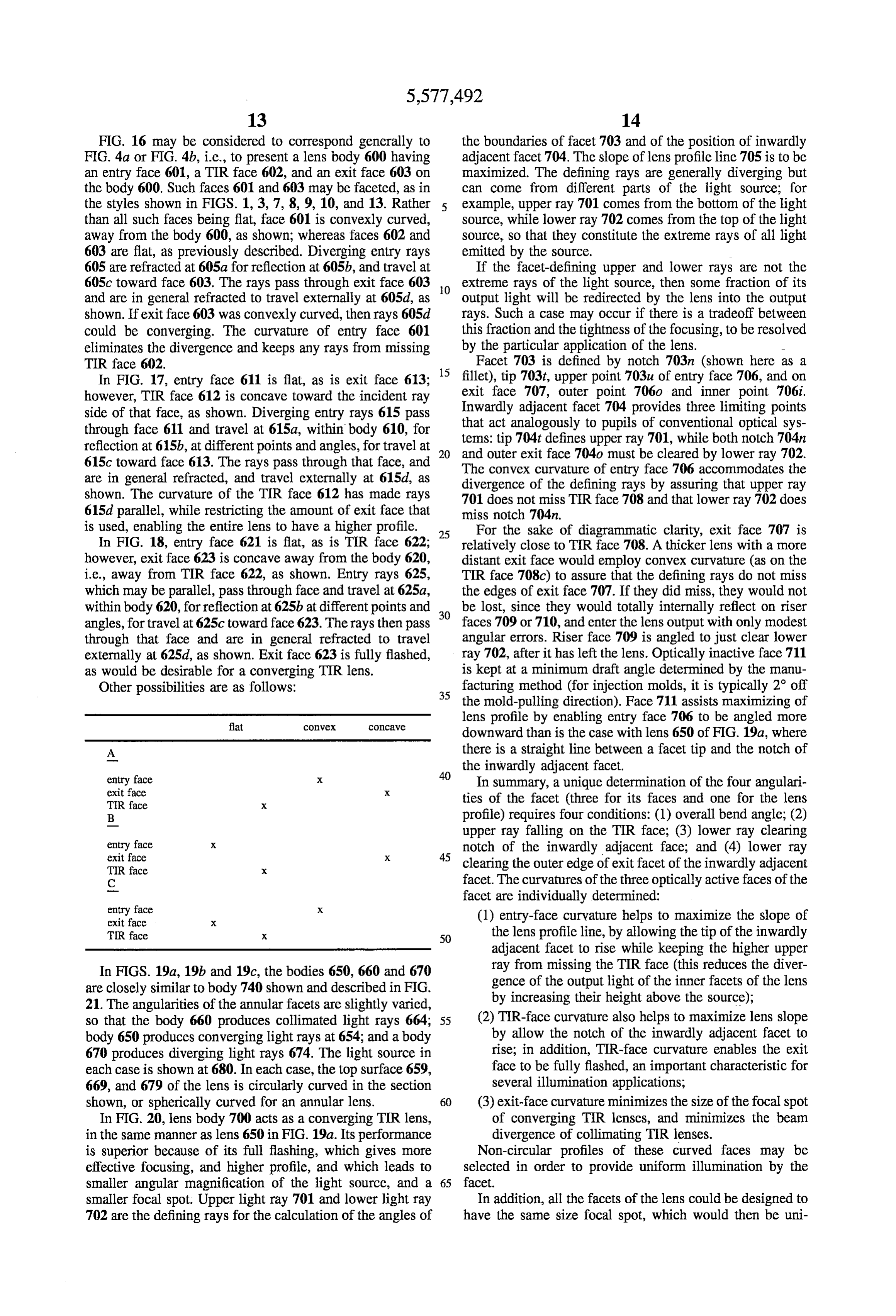
is used, enabling the entire lens to have a higher profile. 25 For the sake of diagrammatic clarity, exit face 707 is In FIG. 18, entry face 621 is flat, as is TIR face 622; relatively close to TIR face 708. A thicker lens with a more however, exit face 623 is concave away from the body 620, distant exit face would employ convex curvature (as on the i.e., away from TER face 622, as shown. Entry rays 625, TIR face 708c) to assure that the defining rays do not miss which may be parallel, pass through face and travel at 625a, the edges of exit face 707. If they did miss, they would not within body 620, for reflection at 625b at different points and 30 be lost, since they would totally internally reflect on riser angles, for travel at 625c toward face 623. The rays then pass faces 709 or 710, and enter the lens output with only modest through that face and are in general refracted to travel angular errors. Riser face 709 is angled to just clear lower externally at 625d, as shown. Exit face 623 is fully flashed, ray 702, after it has left the lens. Optically inactive face 711 as would be desirable for a converging TIR lens. is kept at a minimum draft angle determined by the manu Other possibilities are as follows: 35 facturing method (for injection molds, it is typically 2 off the mold-pulling direction). Face 711 assists maximizing of flat convex COCave lens profile by enabling entry face 706 to be angled more downward than is the case with lens 650 of FIG. 19a, where
A there is a straight line between a facet tip and the notch of
the inwardly adjacent facet.
entry face exit face
In summary, a unique determination of the four angulari
TIR face X ties of the facet (three for its faces and one for the lens B profile) requires four conditions: (1) overall bend angle; (2) upper ray falling on the TIR face; (3) lower ray clearing entry face exit face
notch of the inwardly adjacent face; and (4) lower ray
TIR face X clearing the outer edge of exit facet of the inwardly adjacent C facet. The curvatures of the three optically active faces of the facet are individually determined:
exit face X (1) entry-face curvature helps to maximize the slope of TIR face X 50 the lens profile line, by allowing the tip of the inwardly adjacent facet to rise while keeping the higher upper
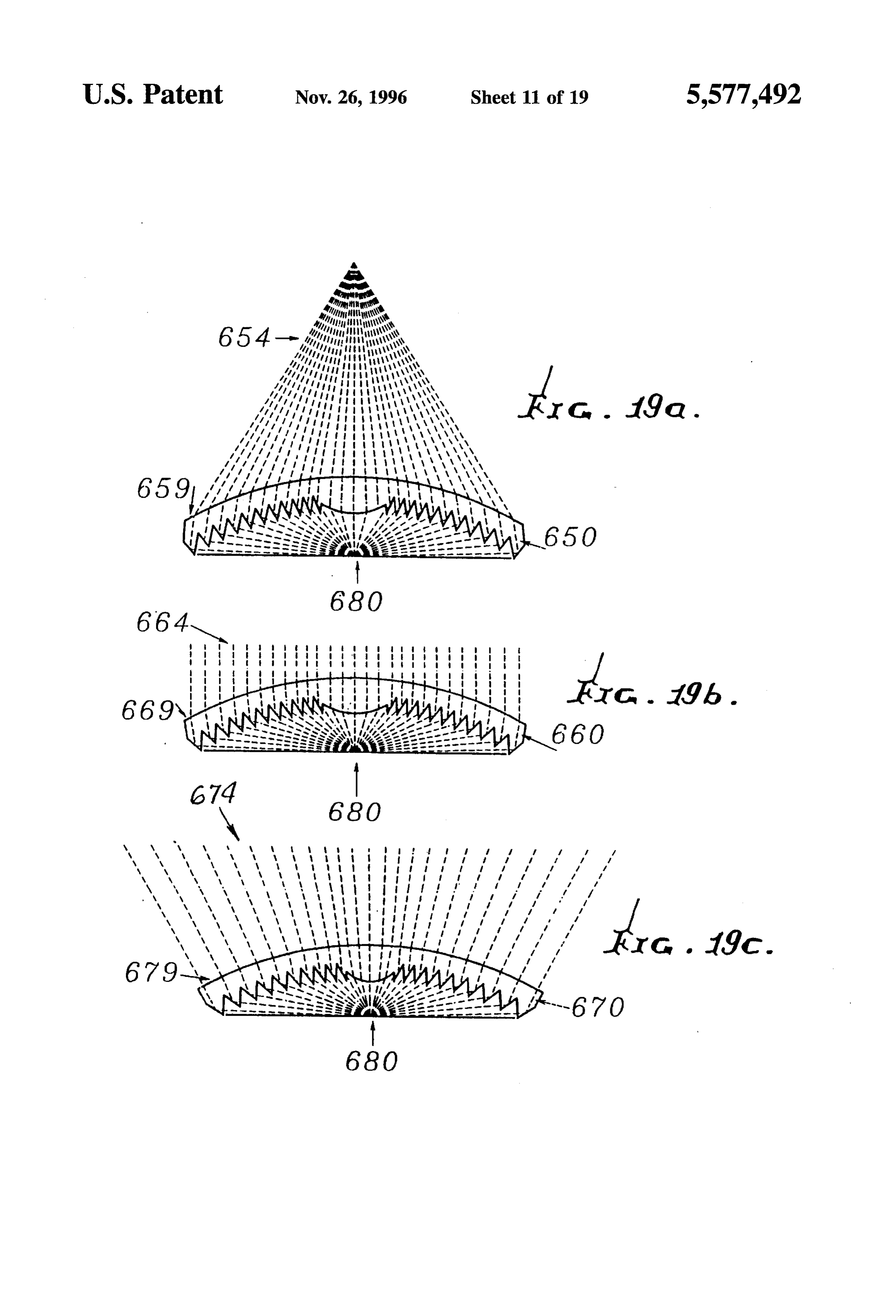
In FIGS. 19a, 19b and 19c, the bodies 650, 660 and 670 ray from missing the TIR face (this reduces the diver are closely similar to body 740 shown and described in FIG. gence of the output light of the inner facets of the lens 21. The angularities of the annular facets are slightly varied, by increasing their height above the source); so that the body 660 produces collimated light rays 664; 55 (2) TIR-face curvature also helps to maximize lens slope body 650 produces converging light rays at 654; and a body by allow the notch of the inwardly adjacent facet to 670 produces diverging light rays 674. The light source in rise; in addition, TIR-face curvature enables the exit each case is shown at 680. In each case, the top surface 659, face to be fully flashed, an important characteristic for 669, and 679 of the lens is circularly curved in the section several illumination applications; shown, or spherically curved for an annular lens. 60 (3) exit-face curvature minimizes the size of the focal spot In FIG. 20, lens body 700 acts as a converging TIR lens, of converging TIR lenses, and minimizes the beam in the same manner as lens 650 in FIG. 19a. Its performance divergence of collimating TIR lenses. is superior because of its full flashing, which gives more Non-circular profiles of these curved faces may be effective focusing, and higher profile, and which leads to selected in order to provide uniform illumination by the smaller angular magnification of the light source, and a 65 facet.
smaller focal spot. Upper light ray 701 and lower light ray In addition, all the facets of the lens could be designed to 702 are the defining rays for the calculation of the angles of have the same size focal spot, which would then be uni
Page 28
formly illuminated. This discussion of FIG. 20 may be 822, for ease of molding. The lens is transparent and may considered an important aspect of the invention, improving consist of molded plastic material. over or not suggested by, subject matter of U.S. Pat. No. A light source 825 is located on axis 802, and just above 4,337,759. the plane 826, is within the confines of the hollow lens, as In FIG. 21, the axis of the annular, radiant energy trans in the above examples; and the rays 827 emanating from mitting body 740 appears at 751. The body has multiple face 802 diverge, as in a floodlight application. The circular annular facets 742 to 746 which are generally concentrically section half-angle subtended by the surface 801 is typically arranged but having tips 742d to 746d progressively closer less than 45° and greater than 25°, and is typically about 35°. to plane 750 normal to axis 751. Face 742a of facet 742 is In FIG. 25, lens body 850 is the same as that of FIG. 21a, convex toward face and face 742b is concave toward face 10 except that the central refractive means has been replaced by 742a in the section shown. This relationship obtains for microscope objective 854, which can slide axially inside the other facets, as shown. lens to focus on sample 851. Characteristic diffuse (i.e., in all A light-emitting diode (LED) 758 is located at the inter directions) emission 856 from sample 851 is collected by section of plane 750 with axis 751 and emits light rays lens 850 and focused on analyzer entrance slit 852. Colli mated laser beam toward the body 740. Ray 753 passes through face 742a, is 15 objective 854 and focused 855 is reflected by mirror 853 into refracted toward TIR face 742b and is reflected toward and on sample 851. Mirror 853 is removable in order to use microscope objective 854 to view passes through upper flat face 748. See also ray 752 passing sample 851 and exactly adjust its position. Lens body 850 through face 743a, reflecting at TIR face 743b, and passing could extend downward below sample 851 to collect even through upper face 748a, angled as shown. All rays passing more of the diffuse emission. Sample 851 may be a glass upwardly beyond faces 748 and 748a are collimated. The 20 capillary containing a gas or liquid, a gold hemisphere transverse width of the body 740 may be from 0.12 to one coated with a sample substance, an integrated circuit on a inch, for example, and the transparent body 740 may consist production line (checking material composition or contami of molded plastic material. A refractive section without nation), or a biological tissue sample.
facets appears at 719. Smaller ratios of lens diameter to LED In FIG. 26, lens body 860 has a cross-section with axis size may have outermost facets large, and successively 25 863, in order to accommodate toroidal (typically fluores inward facets smaller, in order to have a higher lens profile cent) light source 861. Beneath this lamp is annular involute and better collimation curved facets are necessary for. reflector 862, with disc-shaped, planar mirror section 864 In FIG.22, the radiant energy transmitting body 760 may inside it and annulus mirror 865 outside it. Annular lens 866 have the same general construction as shown in FIGS. 20 refracts ray 868, which was reflected from involute 862. Ray and 21. The lens body 760 consists of silicon, or a similar 30 869 is exactly analogous to ray 820 in FIG. 24. Ray 867 is material, for passing infrared rays, but blocking visible light redirected by facet 870. The overall device of lamp, lens, and rays, while transmitting infrared rays. An arc lamp radiant reflector comprise a compact floodlamp that offers much energy source is shown at 764, at the same position as the narrower divergence and much higher efficiency than pos LED in FIG. 20. sible with the prior art of reflector design. A reflector surface 765 may be employed to extend in 35 Referring now to FIG. 27, the lens body 950 is the same plane 766 corresponding to plane 750 in FIG. 21 with a as shown in FIG. 19b or as in FIG. 25, modified to collimate parabolic section 762. The infrared rays emanating at 767 light or a laser beam, supplied as indicated at 955. A light are typically collimated but may be divergent or convergent, source or light-emitting target (laser for example) 951 trans as in FIGS. 19a and 19c. Note that unfaceted central section mits light to faceted side of the TIR lens body 950, the latter 770 refracts rays, as shown. The arc light source at 764 may 40 redirecting the light rays, as shown by the broken lines 956 be produced by anode and cathode elements 764a and 764b. and 980, to pass through first refracting lens means at Top exit surface 759 is circularly curved in the section surface 950a and emerge as collimated light at 955. Such shown; but the lens may have external, stairstep faceting. light then impinges on and passes through the wavelength Protective transparent envelope 769 keeps outside air away selective filter 982 and then through a second lens means from the arc. 45 983 indicated in the example as a focusing Fresnel lens. The In FIG. 23, the body means 780 may have the same or latter redirects or focuses light at 984 onto the sample, or an similar construction as that of FIG. 19a, for producing and analyser, 952.
directing convergent light at 781 into the entrance end 782 A wavelength-selective filter 982 is used to remove pas of a light pipe 783. The lens has an upwardly convex arcuate sively scattered light of the collimated laserbeam 955, while upper exit surface or face 785, an entrance face or faces 786, 50 allowing passage of fluorescence wavelengths, such as those and a TIR face or faces 787. Faces 786 and 787 taper generated in Raman spectroscopy, for stimulated emissions downwardly toward plane 790, corresponding to plane 710 at 952. The filter 982 extends in a plane normal to principal in FIG. 21. A central light source 788 is positioned in the axis 986 defined by the lens 950 and by lens 983, the filter manner of the LED in FIG. 21. A planar back mirror 789 requiring normal incidence of light for good wavelength extends in plane 790 corresponding to plane 710 and faces 55 selection, since the filter wavelength depends upon the angle upwardly. This device may input up to 80% of the light into of incidence. The filter typically removes the laser wave pipe 783, rather than 10% of the light as via a conventional lengths. The auxiliary or second lens means 983 can also act ellipsoidal reflector. to reduce any aberrations introduced by the annular TIR lens In FIG. 24, the body means 800 may have the same or 950.
similar construction as that of FIG. 21c. Circularly curved 60 Also shown, as in FIG. 27, is a microscope objective lens top surface 801 is curved downwardly. The lens axis, in the 954 which can slide axially in a bore in lens 950, and focus case of an annular set of facets, is indicated at 802. Facets auxiliary source light 965 onto the target or laser 951. Note are seen from 803 to 812. A typical annular facet 809 has an the cylindrical periphery 970 of 954 parallel to axis 986, and entrance face 809a and a TIR face 809b. Note ray 820 path sliding in bore 967 of lens 950. A means to adjustably move passing through face 809a and face 801, and totally reflected 65 objective lens 954 axially is schematically shown at 968. at face 809b. In the section shown, each of the faces 809a Auxiliary source light 965 may be redirected by mirror 953, and 809b is flat. All entry faces have draft in the direction as shown, toward lens 954, for focusing onto the target 951.
Page 29
We claim: 9. The system of claim 1 wherein said perimeters of said 1. A radiant energy redirecting system comprising elements project from said cross section to extend annularly a) a radiant energy transmitting body means, about, and define a common axis, said entry faces facing said b) said means comprising multiple elements, each of 5 ZO. incident radiant energy, said exit faces facing said target which acts as a radiant energy redirecting module, 10. The system of claim 1 including a Fresnel lens having on its cross-sectional perimeter an entry face to associated with said body means and located in a mid receive incidence of said energy into the interior of said portion of said body means so as to redirect radiant energy perimeter, an exit face to pass said energy to the through relatively small angles toward the target zone. exterior of said perimeter in a direction towards the O 11. The system of claim 1 including a retro-reflecting reverse side of the body from the side of said incidence, means spaced behind and facing said target Zone so as to and a Totally Internally Reflecting face angled relative redirect radiant energy upon said target Zone. to said entry and exit faces to redirect towards said exit 12. The system of claim 1 including a radiant energy face the radiant energy incident from said entry face, source means situated in said target Zone, and radiant energy c) said body means generally redirecting incident radiant 15 emitted by said source means being redirected by said body energy towards a predetermined target zone situated means in reverse relation to the transmission by the body means in claim 1.
apart from and on the reverse side of said body relative 13. The system of claim 1 including a radiant energy to the side of said incidence, redirecting means situated at said target Zone. d) first lens means associated with at least one of said 14. The system of claim 1 including a wavelength selec faces for redirecting radiant energy passing between 20 tive filter in the path of said radiant energy redirected toward said entry and exit faces via said Totally Internally said target Zone.
Reflecting face, said redirected radiant energy being 15. The system of claim 14 wherein said filter extends in collimated, close proximity to said second lens.
e) and second lens means spaced from said exit face to 16. The system of claim 15 wherein said filter is located receive said collimated radiant energy and to redirect 25 between said first lens means and said second lens means. same toward said target Zone. 17. The system of claim 14 wherein said filter and said 2. The system of claim 1 wherein said first lens means is second lens means define parallel planes. defined at least in part by said Totally Internally Reflecting 18. The system of claim 1 wherein said first and second face. lens means define a principal axis which also passes through 3. The system of claim 1 wherein said second lens means 30 said target Zone.
is a focusing Fresnel lens. 19. The system of claim 17 wherein said perimeters of 4. The system of claim3 including a wavelength selection said elements project from said cross section to extend filter in the path of said radiant energy collimated and annularly about, and define a common axis, said entry faces redirected toward said target Zone. facing said incident radiant energy, said exit faces facing 5. The system of claim 1 including a radiant energy 35 said target Zone, and said axis is normal to said parallel transmitting source from which radiant energy is transmitted planes.
for incidence on said entry face. 20. The system of claim 1 wherein said body means has 6. The system of claim 1 including a radiant energy a central portion about which said entry, exit and Totally transmitting source from which radiant energy is transmitted Internally Reflective faces extend, said central portion com for incidence on said entry face, and wherein said entry face 40 prising a microscope objective. is oriented to receive collimated light rays from said source. 21. The system of claim 20 wherein said body means has 7. The system of claim 1 wherein the Totally Internally a central portion about which said entry, exit and Totally Reflecting face is a body boundary, so that the index of Internally Reflective faces extend, said central portion com refraction “n” of the substance of said transparent body prising a microscope objective. means at said boundary gives total internal reflection of all 45 22. The system of claim 21 including a mirror positioned radiant energy whose incident angle with the normal of said between said first and second lens means to reflect light boundary at the point of incidence exceeds Brewster's angle, toward said central portion of said body means. which equals the inverse sine of the reciprocal of "n". 23. The system of claim 21 including a positioned 8. The system of claim 1 wherein said perimeters of said between said first and second lens means to reflect light elements project from said cross section to extend linearly, 50 toward said central portion of said body means. in parallel relation, said entry faces facing said incident radiant energy, said exit faces facing said target Zone. ck k k :
Provenance
- Collection
- Patents citing this work
- Current assignee
- Innolux Corp
- Original assignee
- TIR Technologies Inc
- Pages
- 29
- Method
- pdftotext (the PDF's own text layer) + pdftoppm 300dpi page scans
- Patent office record
- patents.google.com →
- Source
- Google Patents citing-documents table
- Inventors
- William A. Parkyn, Jr.; David G. Pelka; TIR Technologies Inc
- Published
- 1996-11-26
- Transcribed from
- patentimages.storage.googleapis.com →