patent · US4803608
Rear lights for bicycles and other vehicles
7 February 1989
Page 1 — bibliographic record
United States Patent (19) 11 Patent Number: 4,803,608 Dashwood 45 Date of Patent: Feb. 7, 1989 (54) REAR LIGHTS FOR BICYCLES AND OTHER 4,559,589 12/1985 Sassmannshausen ................. 362/72
FOREIGN PATENT DOCUMENTS
75 Inventor: Nigel J. R. Dashwood, Hertfordshire, 1125858 3/1962 Fed. Rep. of Germany ...... 362/309 England 405208 l1/1909 France ................................ 362/339 73) Assignee: Duracell Inc., Bethel, Conn. 0039980 3/1979 Japan ................................... 362/309 (21) Appl. No.: 944,151 Primary Examiner-Ira S. Lazarus Assistant Examiner-D. M. Cox 22 Filed: Dec. 18, 1986 Attorney, Agent, or Firm-Ronald S. Cornell; James B. (30) Foreign Application Priority Data McVeigh
Dec. 19, 1985 GB United Kingdom ................. 8531275 57 ABSTRACT 51 Int. Cl." .............................................. F21V33/00 The invention provides a light comprising a lamp, a 52 U.S. Cl. ...................................... 362/72; 362/309; reflector or other means defining an optical axis close to 362/326; 362/339 which the major part of the emergent light is distributed 58 Field of Search ..................... 362/61, 80, 72,326, and a lens system having one or more prisms formed on 362/332, 333,339, 308, 309 its nearer face to the lamp and adjacent an edge of the (56) References Cited lens system arranged to trap light from the lamp and
distribute it by total internal reflection through the material of said lens system so that it emerges from the 1,676,464 7/1928 Ryan ................................... 362/309 edge at more than 100 to the optical axis. 3,251,987 5/1966 Wince ................................. 362/339 4,118,763 10/1978 Osteen ................................. 362/339 4. Claims, 3 Drawing Sheets
Page 2
Drawing sheet — no readable text.
Page 3
Drawing sheet — no readable text.
Page 4
Drawing sheet — no readable text.
Page 5
REAR LIGHTS FOR BICYCLES AND OTHER SUMMARY OF THE INVENTION VEHICLES It is an object of the invention to produce a reflector for use in a cycle light, said reflector causing no reduc
FIELD OF THE INVENTION tion in the angular spread of light reflected from it when The present invention is in the field of reflector de it isIt truncated to fit within a rectangular aperture. sign for bicycle lights and in particular bicycle rear reflector for use inobject is a further of the invention to produce a a cycle light, said reflector operating lights which possess a rectangular or other non-circular with a high efficiency at converting light from a light front profile. 10 source into the required output light beam. The present invention is also concerned with a light It is yet another object of the invention to produce an and more particularly, but not exclusively, with sections efficient cycle light with a substantially fully of a bicycle rear light having a lens that generates side illuminated rectangular cross-section which will pro light and/or top-light beams in order to meet the re vide the same angular field of light output in each of quirements of international lighting standards such as 15 two orthogonal directions so that it may be mounted ISO 6742/1 and BS 3648. above a wheel or, after rotation through 90 degrees, BACKGROUND TO THE INVENTION adjacent to the wheel mounting forks. In practice the invention is applicable to almost all reflectors which are
International lighting standards require rear bicycle designed to deliver a significant field angle of light and lights to generate a wide angle horizontal beam of light 20 which are truncated in cross-sectional profile in order with vertical coverage to make vehicles approaching to fit in the light housing.
from the rear or sides aware of the cyclist. At the ex It is a further object of the invention to provide in a tremes of the horizontal field the luminous intensities rear cycle light means for distributing light forwards of required by these standards are considerably lower than the bicycle without introducing components additional at beam centre but are still of great imoprtance from the 25 to the lens system and without reducing the light effi point of view of safety. There is often a further require ciency.
ment for red light to be emitted vertically upwards as a In one aspect the invention provides a lamp having a cone that extends in part towards the front of the cycle. light source, a reflector having a non-circular aperture A great many cycle rear lights possess an overall and a light-distributing lens conforming to the reflector rectangular cross-section, with the long side directed 30 aperture, wherein the reflector has at least one outer vertically, in which the reflector surrounding the light section truncated to define the aperture and at least one source has been truncated to the rectangular form of the inner section arranged so that the or each inner section light. Since it is almost universal for the reflectors to be is circularly symmetric about a common optical axis, of paraboloidal form this truncation results only in a loss and with the profiles of said sections arranged so that: of optical efficiency rather than a loss of angular cover 35 (a) at least one inner section which because it is non age. With this type of reflector it is a requirement of the paraboloidal generates a light beam with far field diver rear lens to extend the angular field sufficiently far to gence; and conform with the lighting standards. (b) the sum angular far field coverage of the reflector In another type of cycle rear light the reflector is the is unaffected by removal of the truncated portions of designed to contribute at least in part to the generation or each outer section.
of the light beam angular distribution rather than to act (a)The arrangement described above has the advantages merely as a collector of light for subsequent angular profile and that aprovides of providing light that may be made rectangular in redistribution by the rear lens. This approach leads to a operating at a much highera optical uniform illumination, (b) of efficiency than lights cycle light which has similar visual properties to a 45 with conventional truncated reflectors because it ena motor car rear light without the very high, and unnec bles greater "wrap around' the light source essary, centre field intensity exhibited by a number of space, and (c) that truncating the reflector in a given causes no cycle rear lights. Should the reflector of a cycle rear loss of the angular field coverage of the light beam from light of this latter type be truncated to a rectangular cross-section then there will be a loss of field distribu 50 the reflector. The light may be made in any convenient tion angle generated by the reflector. aspect ratio and may be mounted with its longer dimen sion horizontal or vertical.
Most commercially available cycle rear lights are In another aspect of the invention provides a light designed with an essentially bowl-shaped rear lens comprising a lamp, a reflector or other means defining moulding which, at least in part, allows the lamp fila an optical axis close to which the major part of the ment to be directly visible at the extremes of horizontal 55 emergent light is distributed and a prism and/or lens field coverage and in the vertical field. Since the lumi nous intensity of the lamp is invariably greater than the system formed on its nearer face to the lamp with one or more prisms adjacent an edge of the lens system ar far field luminous intensities at the extreme angles ranged to trap light from the lamp and distribute it by which are required by the lighting standards, direct total internal reflection through the material of said lens viewing of the filament, usually by way of a truncated system so that it emerges from the edge at more than reflector and the lens moulding, is acceptable. 100' to the optical axis.
A second design of cycle rear light lens relies on One advantage of the present light is that it allows refraction or reflection within the optical system of the considerable design freedom for styling, matching to light to generate the required field coverage. Care must the front cycle light (which must have quite different be exercised in this approach so that areas of the re 65 light output requirements in order to meet international quired field coverage are not omitted or produced at lighting standards), and optimising the optical perfor too low a luminous intensity to reach the relevant light mance. In particular, and unlike a conventional cycle ing standards. rear light, the lamp does not have to be sited in such a
Page 6
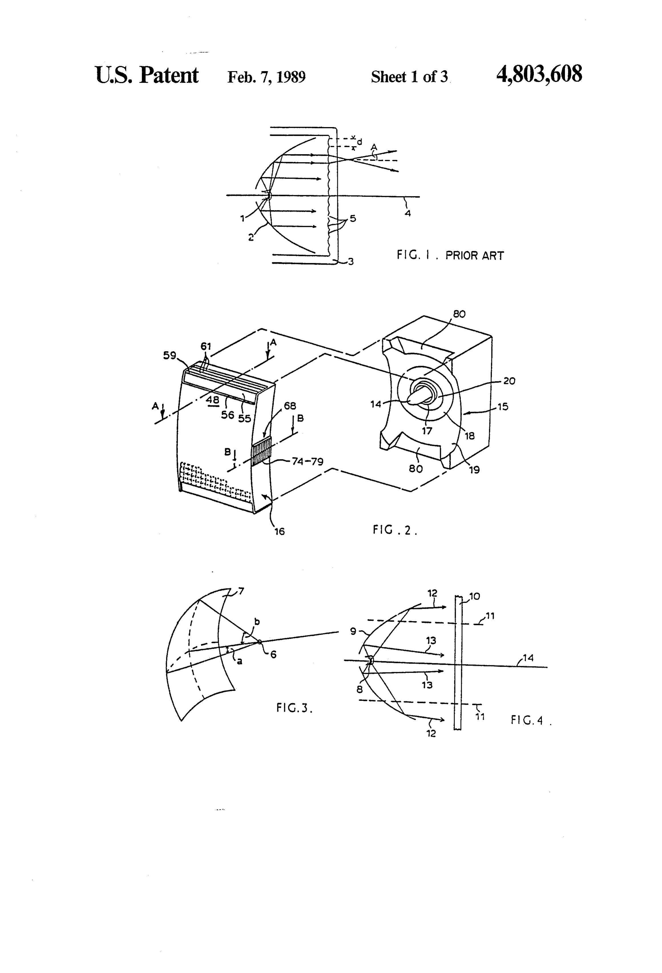
position that its filament can be seen by uninterrupted FIG. 9 is a fragmentary section on the line B-B of viewing at all parts of the illuminated field. This advan the side of the lens of the cycle rear light of FIG. 2. tage arises because the refraction or reflection imparted DETALED DESCRIPTION OF PREFERRED by the optical system acts so as to change the direction EMBODIMENT of the light leaving the lamp filament to illuminate a particular part of the field. Consequently, the cycle rear The general construction of a conventional front or light main housing may be constructed of an optically rear cycle light is illustrated in FIG. I. A light source 1, opaque material without the need for a bulbous lens which is most commonly a tungsten lamp with compact dome common to most types of cycle rear light. A filament, is sited at a focal point of a reflector 2. The second advantage of the invention is that the reflection 10 light reflected from 2 passes through a lenticular struc and refraction imparted to the light from the lamp fila ture 3 which alters the distribution and angular extent of ment is carried out in such a way that the effects of dust, the output light beam to the desired shape. Almost road grime and scratches do not unduly affect the long invariably the reflector 2 is of paraboloidal form so that term light output level and distribution from the light. if the light source 1 is very small the reflected light 15 beam is comprised only of light rays travelling parallel
DESCRIPTION OF PREFERRED FEATURES to the reflector optical axis 4. In practice the spread of Advantageously the lens has side flanges carrying light from 2 may be as high as 7 degrees owing to the refractive prismatic arrays that register with the trunca finite size of the lamp filament. It is common for a large tions in the reflector and that serve to produce a lateral 20 part of the light bean leaving the reflector 2 to impinge distribution of light. upon an array of small spherically or cylindrically sym Preferably the reflecting prisms that are formed at the metric lenses within the lenticular structure 3. These ends of the lens system are arranged to trap direct light lenses are identified by numeral 5 in FIG. 1. A colli from the lamp filament and the minimum angle of inci mated beam of light incident upon a lens 5 will be con dence innin of direct light from the lamp filament on the verted into a beam with semi-angular extent Agiven by face of the or each prism at which said direct light is 25 refracted into said material is given by: A searc tan (d/2f) (l)
Sin innin= n sin de-6 where d is the width or pitch of the lens and f is its focal where n is the refractive index of said material, cb is the length. For typical values f= 12 mm, d = 3 mm and the critical angle for total internal reflection and 6 is the 30 angle A=7 degrees. Thus it is clear that the distribution angle between the incident face and the face at which of light leaving lens 3 tends to be concentrated near the total internal reflection occurs. optical axis 4. For larger angles from the optical axis the The lens system may be cylindrically convex over its output light beam is most often made up from forward major part when viewed from in front of the light and emitted direct light from the lamp and is therefore lim an edge region bounding said major part is formed with 35 ited in its intensity by the luminous intensity of the scarp and dip faces meeting at an obtuse angulation, the SOULC.
dip face receiving the incident totally internally re FIG. 3 illustrates the truncated form of the reflector flected light. The edge at which light emerges is conve when the cross-section of the cycle light is rectangular. niently of convex profile so that light emerges at a range The effect of truncating the reflector is to reduce the of angles. The lens system may then be rearwardly angular collection of light from the source in one direc flanged adjacent the edge at which said light emerges tion with respect to the orthogonal direction. Thus, as and said flange carries cylinder or spherical lens means shown, the subtense angle b of the reflector 7 with that receive direct light from the lamp and distribute it respect to the light source 6 is greater than the similar over a range of angles. subtense angle a in the orthogonal direction. For a pa 45 raboloidal reflector the truncation results only in a re
BRIEF DESCRIPTION OF DRAWINGS duction in light collection efficiency and has no practi An embodiment of the invention will now be de cal effect on the angular field of the reflected light. scribed, by way of example only, with reference to the Consequently, in FIG. 1, the angular extent of the light accompanying drawings, in which: beam leaving the lenses 5 will be the same as when the FIG. 1 is a section of a conventional cycle rear light; 50 reflector 2 is not truncated.
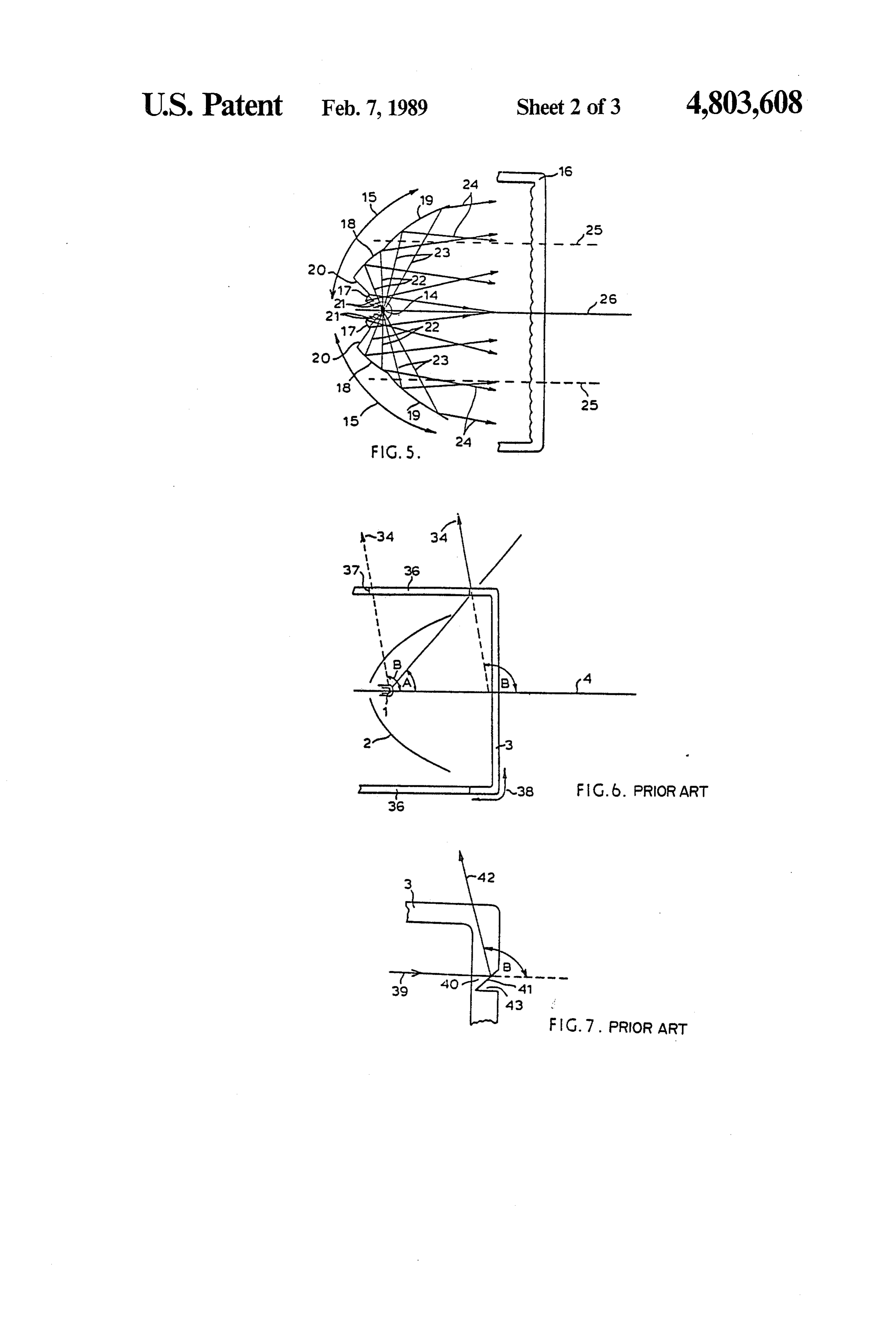
FIG. 2 is a general view of a cycle light according to FIG. 4 is a cross-section through a light which con the invention with the lens removed to reveal the reflec tains a reflector designed to produce a diverging beam tor; of light. Light from the source 8 is formed by the reflec FIG. 3 is a view of the reflector and light source tor 9 into a diverging beam which impinges upon lens showing the effect of truncation; 55 10 (no detail shown). Should the reflector be truncated FIG. 4 is a cross-section through a light that contains so that regions beyond the broken lines 11 are removed, a reflector designed to produce a diverging beam but then the marginal rays such as 12 will be removed from that is otherwise conventional; the light bean. Unless rays such as 13, which still re FIG. 5 is a cross-section of the cycle light of FIG. 1 main after truncation, diverge in the far field at the same illustrating diagrammatically the way that the reflector, 60 angle with respect to the optical axis 14 as rays 12 then light source and lens cooperate; the far field angular divergence of the light beam leav FIG. 6 is a diagrammatic vertical section of an illus ing reflector 9 will be reduced in the plane of trunca trative cycle rear light according to the prior art; tion.
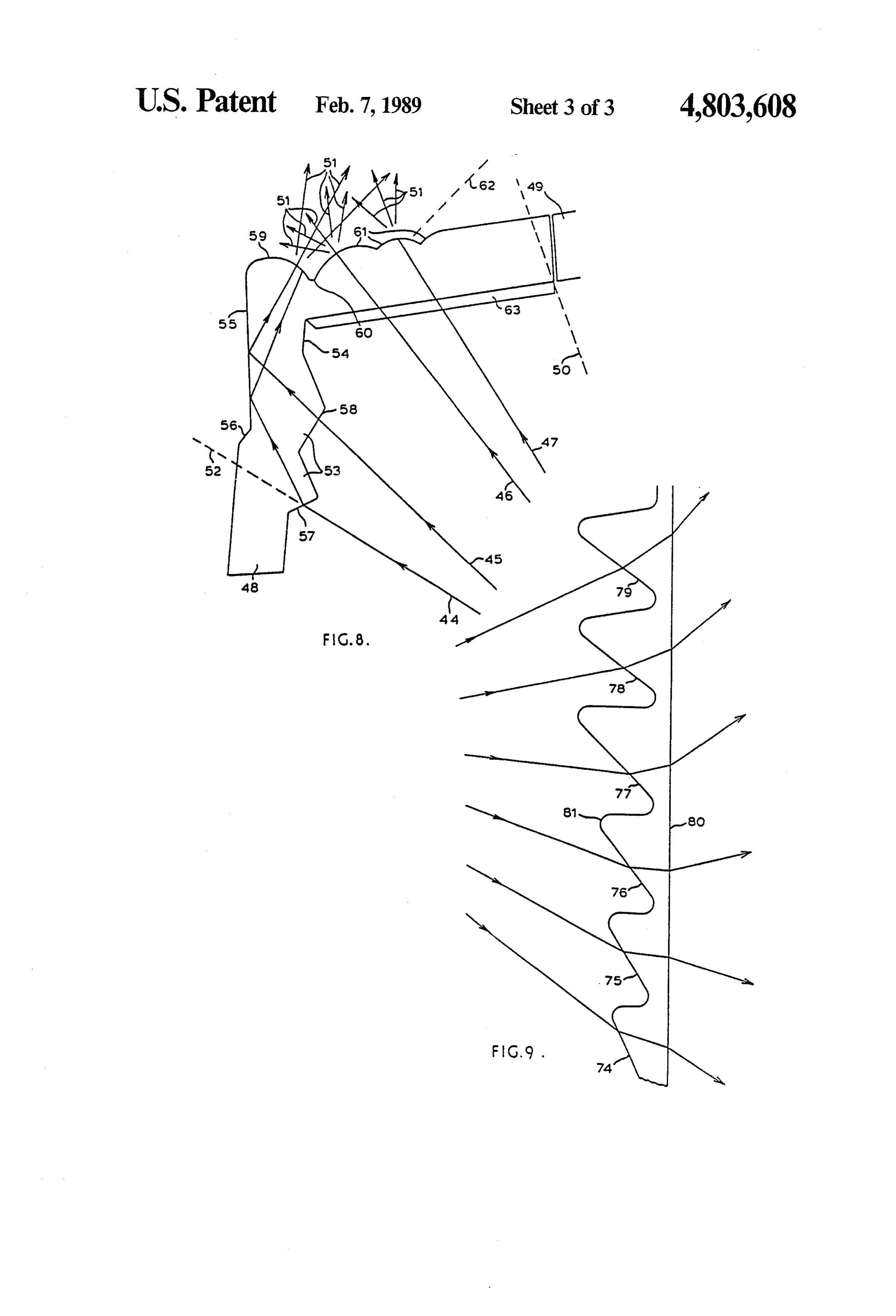
FIG. 7 is a fragmentary section adjacent the side of a Unfortunately, it is very common from consider lens is a second cycle rear light according to the prior 65 ations of the space available for the reflector, its aspect art; ratio, the optical collection efficiency and the genera FIG. 8 is a fragmentary section on the line A-A of tion of the appropriate distribution of intensity with the end of a lens in the cycle rear light of FIG. 2; and field angle from the light, for a single reflector curve in
Page 7
which equi-angular extreme field rays such as 12 and 13 the region between the broken lines 25, which may or exist not to be available. Thus, unless the truncated may not be equally disposed about, and parallel to, the plane of the reflector corresponds to a direction in optical axis 26 of the light. The truncation removes all which reduced efficiency and angular field coverage is or part of the reflector section 19 and part of the lens acceptable an alternative solution has to be sought. 5 array within 16. However, the angular field coverage of Although such a solution may be realisable by means of the light will be unaffected by the truncation; only the a more complex structure within the lens 10, comprising collection efficiency from source 14 and the distribution elements with greater light bending power in one direc of intensity over the field will be altered to some degree. tion compared to the orthogonal direction, it generally This is because there still remains complete angular field leads to a lens design which is a compromise between 10 coverage via reflector sections 17 and 18 right up to the the requirements of the two directions, and at reduced extreme rays 24 from untruncated reflector section 18. efficiency, and which has limited appeal as far as indus Since the angular field of the light beam emitted from trial styling is concerned. the light is unaffected by the truncation of the reflector FIGS. 2 and 5 illustrate an alternative solution to the the light may operate with substantially equal effect problem in the manner of the invention and show a 15 when mounted in either of the two orthogonal direc cross-section through a cycle lamp in a plane for which tions.
reflector truncation is small or not present. Light from FIGS. 6 to 8 illustrate the provision of rearwardly a source 14 is collected by the whole reflector 15 and and upwardly directed light from an end of the lens. directed towards a lenticular structure 16. The reflector FIG. 6 illustrates the layout of a cycle rear light. A 15 is comprised of at least two sections of which, firstly, 20 compact light source 1 mounted in a reflector 2 illumi at least one section, which is not the outer section, gen nates a semi-angular field which extends from the axial erates a light beam with far field divergence, and of direction defined by the optical axis 4 of the reflector 2 which, secondly, the sum angular field coverage of all (i.e. the backwards direction parallel to the axis of the but the outer section and that part of the outer section bicycle) to the extreme vertical or horizontal direction which is not truncated is equal to the total angular field 25 designated by arrowhead 34 in which light returns to coverage from all sections of the reflector when all the cyclist. In front of the lamp 1 is sited the lens system sections of the reflector are present. 3 and shown without detail, which serves in part to In FIGS. 2 and 5 the reflector 15 comprises three convert the light reflected from reflector 2 into a beam sections designated 17, 18 and 19. The sections may be of the appropriate intensity/angle distribution. Sur edge-abutting, as between sections 18 and 19, or they 30 rounding the reflector 2 is an optically opaque housing may be separated by an intermediate section such as 20, 36 which serves to support all the components as well as between 17 and 18, which is general subtends an insig batteries if applicable.
nificant angle at the light source 14, or they may com Because of the presence of the opaque housing 36 the prise a combination of the two. The lenticular structure field of direct light from the light of FIG. 6 is limited to 16 can be identical to that designated as 5 in FIG. 1. At 35 semi-angle A whereas the requirements of the lighting least one of the reflector sections within reflector 15, standards may be for a larger semi-angle coverage B. although not the outer section 19, may be of paraboloi Many cycle rear lights achieve the semi-angle B by both dal form. At least one of the reflector sections, e.g. reducing the extent of the opaque housing 36 to finish at section 17, within reflector 15 may be substantially flat 37 and extending the lens 3 to take its place. Then, in the plane of FIG. 5. Two or more of the reflector 40 together with a reflector 2 which is either segmented or sections within reflector 15 may generate equi-angular truncated in the angular regions where light is required, field coverage of light. One or more of the reflector the lamp filament may be seen from all parts of the field. sections within reflector 15 may generate a converging This solution leads to a design of light which is uniquely output light beam. Thus, for example, the section 17 different in appearance from a cycle front light and may, with a compact light source, produce a far field 45 prevents dual usage of many components of the front divergence of semi-angle about 3, the section 18 may and rear lights.
produce a far field divergence from about +20 to Other cycle rear lights incorporate prismatic struc about -2 depending upon the radial position of the tures in the outermost regions 38 of the lens 3 to refract incident light, and the section 19 may produce a far field and/or reflect light into directions not covered by ei divergence of semi-angle -20. 50 ther the direct light emitted by the lamp filament or the Either all or part of the light leaving reflector 15 may light from the reflector. One difficulty with this ap be redistributed angularly by the lens 16 or lens 16 may proach is the possibility of creating dark areas in the have no redirectional effect on the light. angular field caused by either removing light from these Rays designated 21, 22 and 23 are contained within regions in order to illuminate the extreme regions or by the light from source 14 which impinges on reflector 15. 55 light obstruction owing to the prismatic structure itself. Rays 21 strike reflector section 17; rays 22 strike reflec FIG. 7 illustrates the manner in which a cycle rear tor section 18; and rays 23 strike reflector section 19. In light with the general layout shown in FIG. 6 may the particular form of the invention shown the light increase its semi-angular field coverage from A to B in reflected from each of the three sections 17, 18, 19 con this manner. An input light ray, designated by numeral prises a diverging beam, with the outer margins of the 60 39, which may either be generated via the reflector 2 total output light beam designated by rays 24. When the (FIG. 6) or directly from the lamp filament 1, strikes a total light beam impinges upon the lens array within 16 section 40 of the front lens 3. Within section 40 is a all or part of it is further diverged in the far field ap recessed flat surface 41 which is inclined to ray 39 at a proximately according to equation (1). sufficient angle to ensure that total internal reflection of The cross-section of the cycle light shown in the 65 ray 39 occurs. The reflected ray 42 leaves surface 41 at direction orthogonal to that of FIG. 5 is substantially the required angle B, and by suitably siting surface 41 in identical to FIG. 5 except for the outer regions of the the lens 3 (FIG. 6) it can be ensured that ray 42 is not figure. Such a cross-section is illustrated in FIG. 5 by blocked by the opaque housing 36. Clearly, because
Page 8
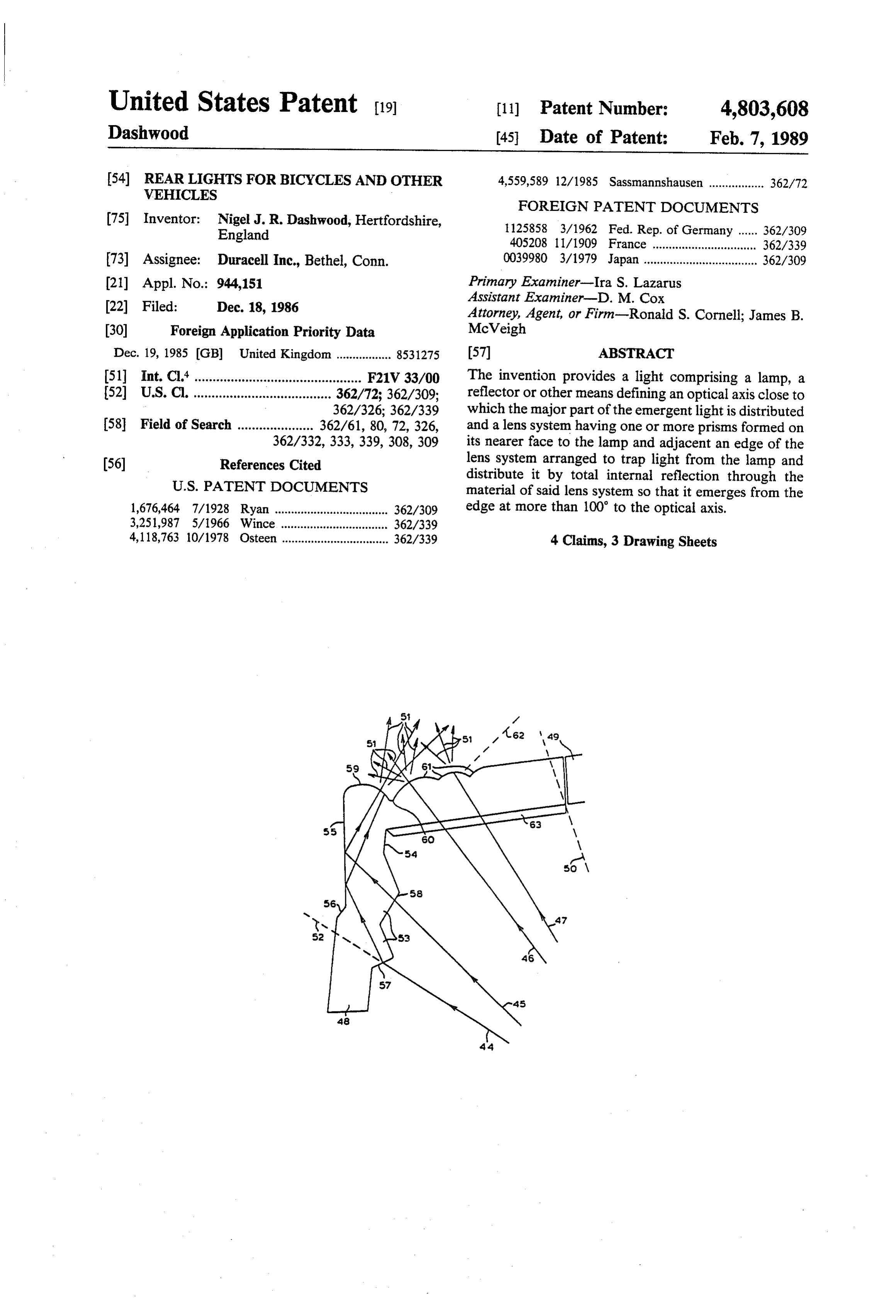
total internal reflection occurs at surface 41, ray 42 By careful design of the optical system parameters it appears essentially of the same luminous intensity as can be ensured that all the light leaving structure 59 is incident ray 39. In practice there will be refraction at sited significantly far above the root 60 so as not to be either side of the total internal reflection at surface 41 as affected by dust and dirt, and likewise for array 61, ray 39 enters and ray 42 leaves the lens 3. The degree of 5 although these lenses may not be of high numerical refraction will be dependent on the angles of incidence aperture and therefore so bulbous as lens 59. The action at the various air/iens interfaces. A particular drawback of structure 59 and array 61 is not unduly harmed by of the system shown in FIG. 7 is that in use dust and rain which simply forms drops that further diffuse the road grime coagulated with water will settle in the light.
recess 43 and reduce the efficiency of reflection at Sur 10 Lens 59 and array 61 may alternatively be sited on the face 41. Cleaning of such a small recess, particularly if inner surface 54 of lens section 48. Should this be the the lens is manufactured as a plastic moulding, can also case then the outer surface 55 of lens 48 will be resistant very easily lead to scratching and reduced efficiency. A to the effects of dust and water. further drawback of the system shown in FIG. 7 is that The lenses of array 61 may be of spherical form. it is not possible to present a smooth or angular indenta 15 Alternatively they may be cylindrical, in which case a tion-free outer surface to the lens 3 of which section 40 further lenticular array 63, similar to 61 and aligned is a part. A yet further and major disadvantage is that perpendicular to it, must be sited on the surface 54, in owing to the refractive indices of the materials used it is order that light spreading in a plane perpendicular to not possible to achieve a deviation angle of more than FIG. 3 will be assured.
about 95. Referring now to FIG. 2, it may be noted that the An improved form of reflective/refractive optical ends of the lens 3 are symmetrical so that some light is system to generate light beams beyond the extent of distributed direct light from the lamp is illustrated in FIG. 8. Rays larly, if the forwardly light is above and below the lens. Simi mounted so that its major direction 44 to 47 are contained within a spread of direct light is horizontal, light emerges through lens 59 and array 61 from a lamp filament (not shown) or from a portion of 25 as a sideways cone, which enables the light to be the reflector and impinge upon an optically transparent mounted at will to either side of the bicycle. combined prismatic/enticular structure at the top edge As has been described above, the reflector is trun section 48 of the cycle light lens. The edge of an opaque cated at sides 69 thereof and the lens 3 is formed with housing 49 extends sufficiently far beyond the lamp to distributing regions 68 that serve in the normal vertical meet edge section 48 that useful direct light from the 30 mounting attitude to create horizontal sideways light lamp filament is confined to within the extreme bound beams to increase visibility. The regions 68 contain ary defined by the broken line 50. It is required that prismatic arrays that deviate light over a greater range light designated by the arrowheads 51 should leave the than a lens system and operate with direct light from the edge section 48 to provide full coverage from beyond line 50 to ray 52 which is an extension of the ray 44. 35 SOCs.
Lens section 48 contains one or more prismatic sections A typical refractive prismatic array is illustrated in FIG. 9. A series of substantially flat surfaces 74 to 79 are 53, these being on the back surface 54 of lens 48, which inclined serve to direct part of the input beam of light from the at incrementally increasing angles to the light lamp filament to the front surface 55 at such an angle of emanating from a compact filament source (not shown). incidence that total internal reflection (TIR) will occur. 40 The surfaces 74 to 79 are linked together by scarp sur Surface 55 may contain a generally obtuse angular step faces of the array which are designed to intercept as change at 56 in order that the TIR condition is more little as possible of the input light beam. Light which is readily met. The angles of prisms 53 are chosen to either refracted by the surfaces is further refracted by the refract light, as shown at surface 57, or to pass light plane surface 80 opposite the prismatic array so that without deviation, as shown at surface 58, as necessary 45 light leaves 80 with a substantially increased angular for TIR to occur. Light reflected at surface 55 travels spread compared to the input beam. It is preferable that through the medium of lens section 48 until it impinges the tips of the array, such as that at 81, are curved. In upon a lenticular edge structure 59 which acts so as to this way, the tendency of the discrete surfaces 74 to 79 spread, in the far field, the beam of light which strikes it. to produce a series of stripes in the output beam is re Light that has left structure 59 is designated by some of 50 moved because the tip radii cause smearing of light the arrowheads which comprise 51 and is directed over between the stripes.
an angular range which extends beyond the boundary What is claimed is:
50 up to the required extreme angle defined by the line 1. A light comprising a lamp, means defining an opti 62. cal axis close to which the major part of the emergent The output light distribution which is ultimately gen 55 light is distributed and a lens system having formed on erated by the beam containing rays 44 and 45 is supple its nearer face to the lamp one or more prisms adjacent mented by a second output beam of light of which rays an edge thereof and being arranged to trap direct light 46 and 47 form part of the input. This light passes from the lamp and distribute it by total internal reflec through surface 54 without significant deviation and tion through the material of said lens system so that it impinges upon a second lenticular structure 61 adjacent 60 emerges from the edge at more than 100 to the optical to 59. The lenses within structure 61 act so as to spread axS.
the incident light over a range which extends from at 2. A light according to claim 1, wherein the minimum least the boundary defined by 52 to at least overlap the angle of incidence innin of direct light from the lamp on beam emitted from 59. In this way there is continuous the face of the or each prism at which said direct light coverage to the extreme boundary designated by the 65 is refracted into said material is given by: line 62. The ends of the reflector 15 are cut away at 80
(FIG. 2) to allow rays 46, 47 to pass direct to the struc Sin innin-n sin disc-8 ture 61.
Page 9
where n is the refractive index of said material, dc is the and dip faces meeting at an obtuse angulation, the dip critical angle for total internal reflection and 6 is the face receiving the incident totally internally reflected angle between the incident face and the face at which light.
total internal reflection occurs. 4. A light according to claim 1, wherein a plurality of 3. A light according to claim 1, wherein the lens said prisms is located adjacent said edge, and the edge at system may be cylindrically convex over its major part which said light emerges is of convex profile so that when viewed from in front of the light and an edge light emerges at a range of angels. region bounding said major part is formed with scarp ck k se ck ck
Provenance
- Collection
- Cited prior art
- Original PDF
- patentimages.storage.googleapis.com →
- Filed
- 1986-12-18
- Pages
- 9
- Method
- pdftotext (the PDF's own text layer) + pdftoppm 300dpi page scans
- Source
- Google Patents bibliographic record
- Granted
- 1989-02-07
- Inventors
- Nigel J. R. Dashwood; Duracell Inc USA
- Transcribed from
- patentimages.storage.googleapis.com →