patent · US3941993
Illuminating device in particular for an operating table
2 March 1976
Page 1 — bibliographic record
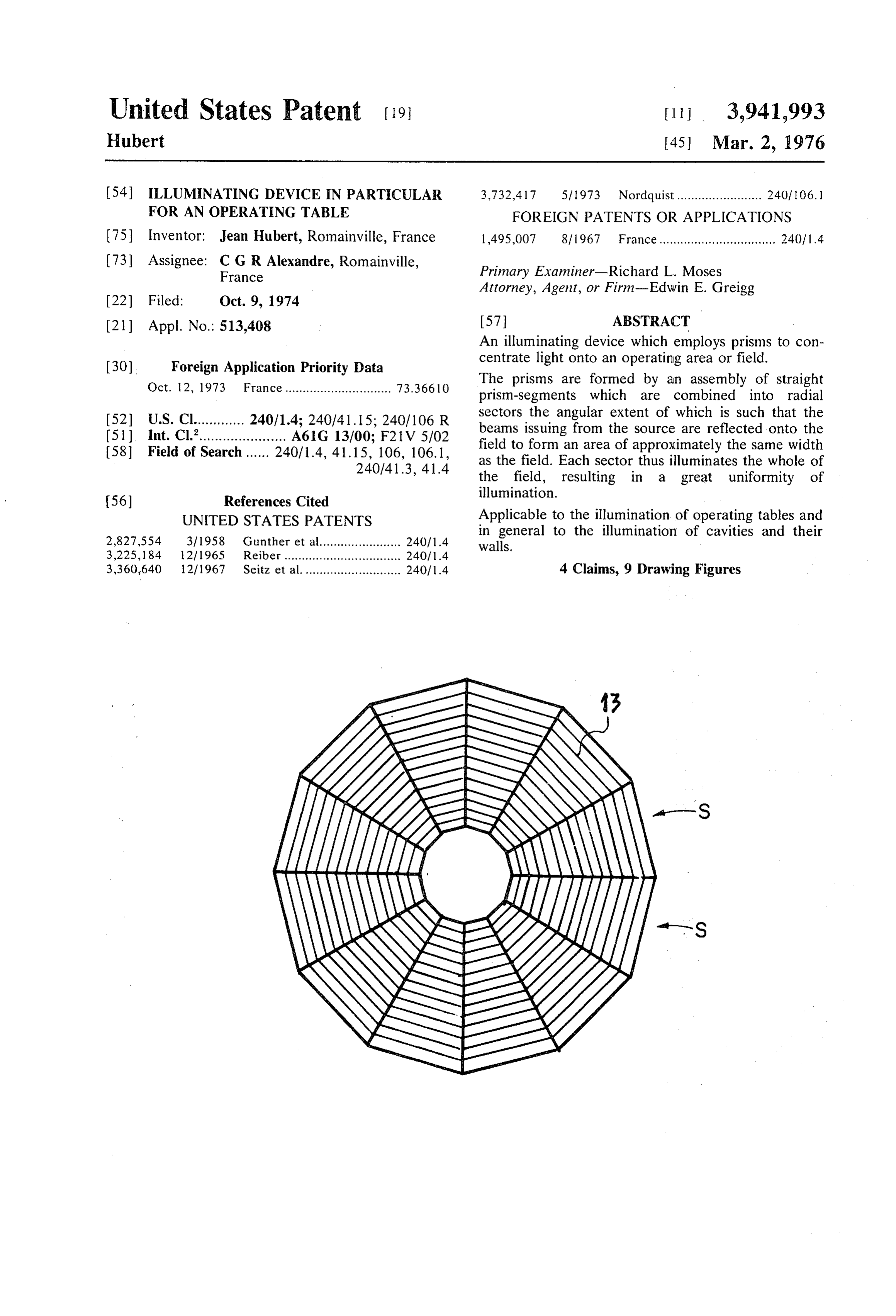
United States Patent (19) [11] 3,941,993 Hubert (45) Mar. 2, 1976 54) ILLUMINATING DEVICE IN PARTICULAR 3,732,417 5/1973 Nordquist........................ 240, 06.1 FOR AN OPERATING TABLE FOREIGN PATENTS OR APPLICATIONS 75 Inventor: Jean Hubert, Romainville, France 1,495,007 8/1967 France................................. 2401 1.4 7 Assi (73) SS1gnee : Alexandre, Romainville, Primary Examiner-Richard L. Moses Attorney,y Agent, or Firm-Edwin E. Greigg
(21) Appl. No.: 513,408 57 ABSTRACT An illuminating device which employs prisms to con (30) Foreign Application Priority Data centrate light ont an operating ignt onto ti area or field.
Ile
Oct. 2, 197 The prisms are formed by an assembly of straight ct. 2, 1973 France.............................. ''' prism segments which are combined into radial s sectors the angular extent of which is such that the
E. Af & a 240/ id: :: . beams issuing from the source are reflected onto the 58) Fi id is - - - - -h a a 240, 4, 41.15 s 106. 106.1 field to form an area of approximately the same width e O Sea ...... a . . 240,413 41 4 as the field. Each sector thus illuminates the whole of says s a the field, resulting in a great uniformity of 56) References Cited illumination.
UNITED STATES PATENTS Applicable to the illumination of operating tables and 2,827,554 3/1958 Gunther et al....................... 240/1.4 in general to the illumination of cavities and their walls.
3,225,184 21 1965 Reiber ........ 240/1.4 3,360,640 12/1967 Seitz et al........................... 24011.4 4 Claims, 9 Drawing Figures
Page 2
Drawing sheet — no readable text.
Page 3
Drawing sheet — no readable text.
Page 4
Drawing sheet — no readable text.
Page 5
Drawing sheet — no readable text.
Page 6
Drawing sheet — no readable text.
Page 7
which the illumination of the field is substantially uni
LLUMINATING DEVICE IN PARTICULAR FOR form.
AN OPERATING TABLE According to a feature of the invention, in an illumi nating device which employs prisms for concentrating
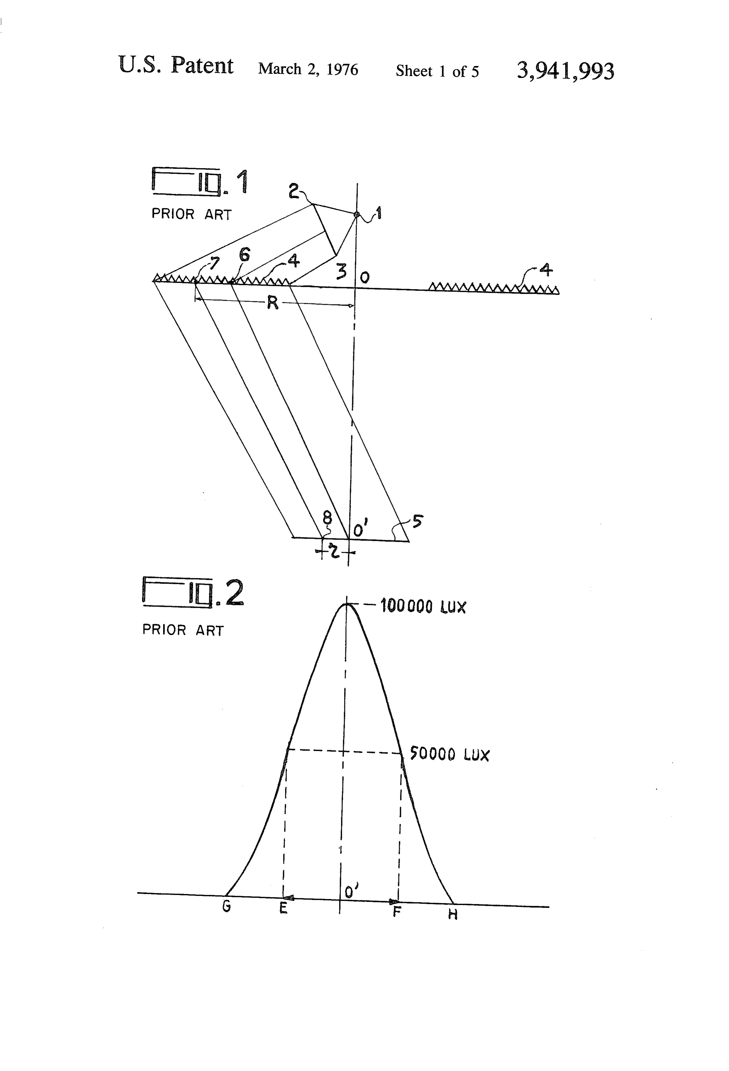
The invention relates to an illuminating device, par light, the prism assembly is formed by juxtaposing a ticularly for an operating table, and more particularly plurality of straight prism-segments in such a way that to such a device which uses prisms rather than mirrors the light emitted by a source is not concentrated onto to concentrate the light rays onto the operating area or the axis of the system but is simply reflected towards field. the field, without being concentrated in any other way Such a device is usually in the form of a body of 10 than by the superimposition of the light beams re revolution about an axis, and the light emitted by the flected by the various prism segments. source or sources is redirected by a toroidal optical In accordance with another feature, the prism seg system onto the plane of the prisms in substantially ments are combined into radial sectors the angular parallel layers, the prisms being arranged concentri 15 extent of which is such that the beams from the source cally with the axis in a plane normal thereto. are reflected onto the field to form a trace of which the A cross-section of a prior art illuminating device width is approximately the same as the width of the which employs prisms is shown in FIG. 1. At 1 is situ field.
ated a source, which is as nearly a point-source as pos The invention will be better understood and other sible, the light from which is refracted by the toroidal 20 features will become apparent from the following de optical system 2 (only the rays and the part of this scription of a preferred embodiment, which is given optical system situated on the left-hand side are shown) with reference to FIGURES which show: and is directed in substantially parallel layers onto a FIG. 1, a diagrammatic cross-section through a prior plate 3, which carries a large number of circular annu prisms,art illuminating device which employs circular annular lar prisms 4 forming a ring arrangement of centre 0. 25
These prisms are so orientated as to receive the rays FIG. 2, a diagram of the field of illumination obtained emitted by the optical system 2 normally to one face. with this device, shown in FIG. 1.
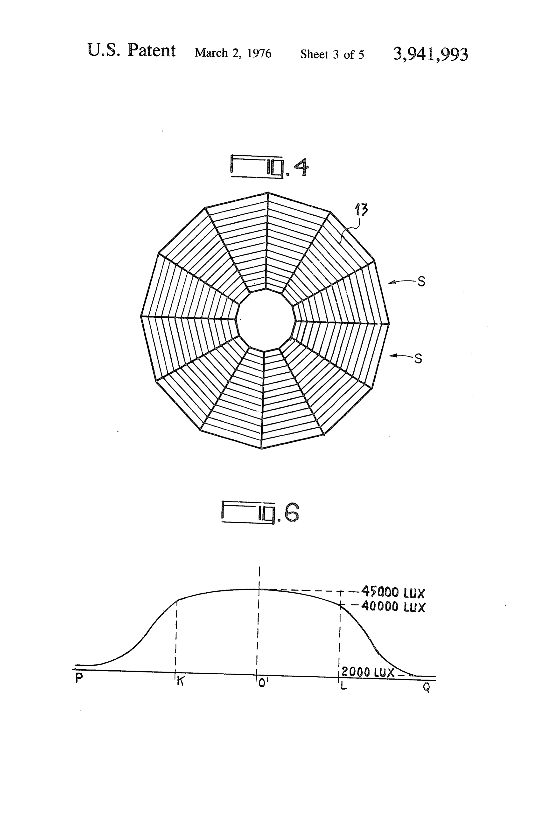
The angle at their apex is so calculated that, as a result FIG. 3, a diagrammatic cross-section through a de of total reflection and then refraction on emerging vice according to the invention, from their third face, the incident rays are redirected in 30 FIG. 4, a plan view of the prism segments, the desired direction. The angle at the apex of the the paths aofperspective
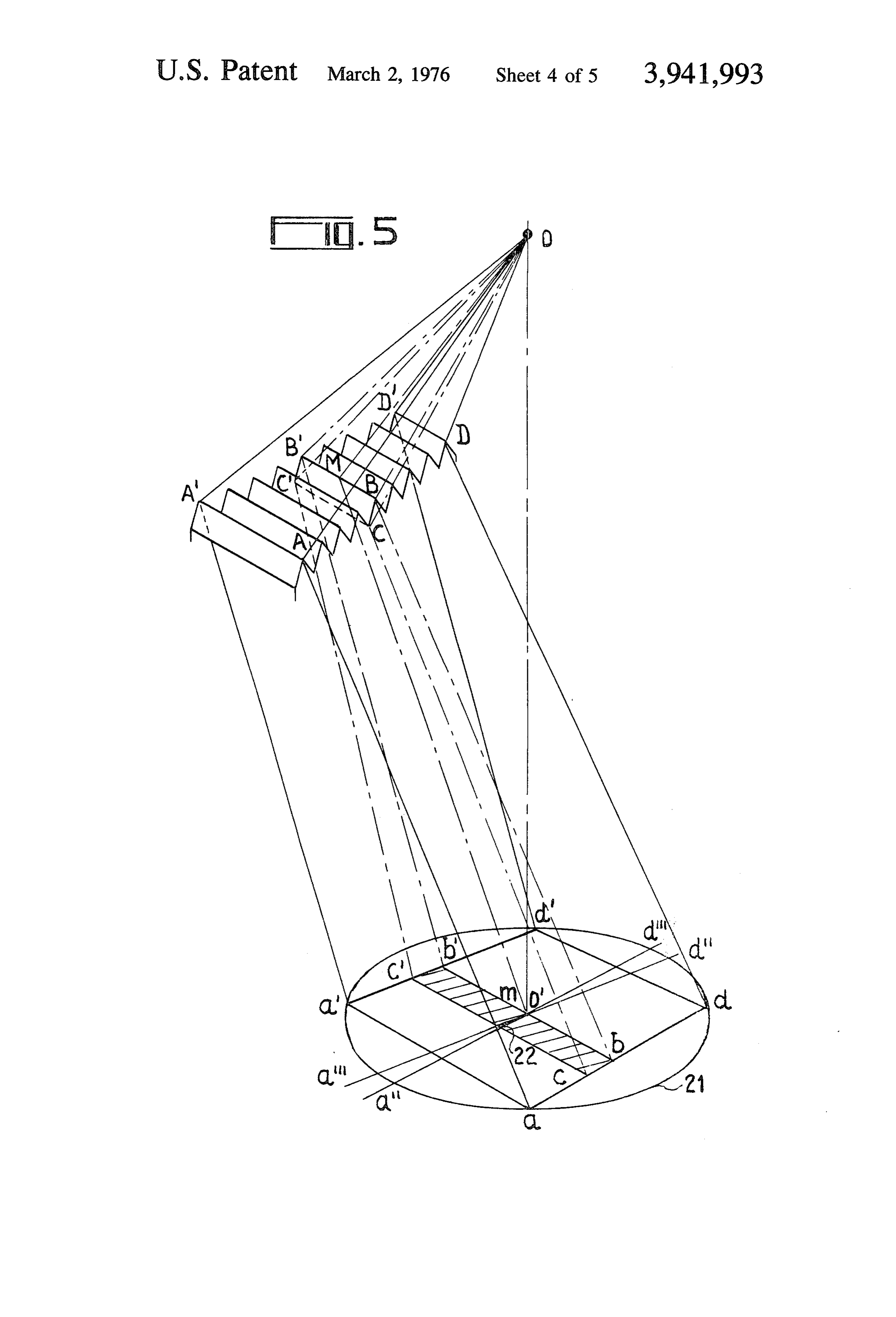
the rays, view of a prism sector showing prisms may thus vary from one prism to another but, in practice, the prisms are split up into groups all of which FIG. 6, a diagram of the field of illumination with a have the same angle. The light beams reflected by the device according to the invention, rings of prisms is thus redirected onto an operating field 35 light rays7ain ,the
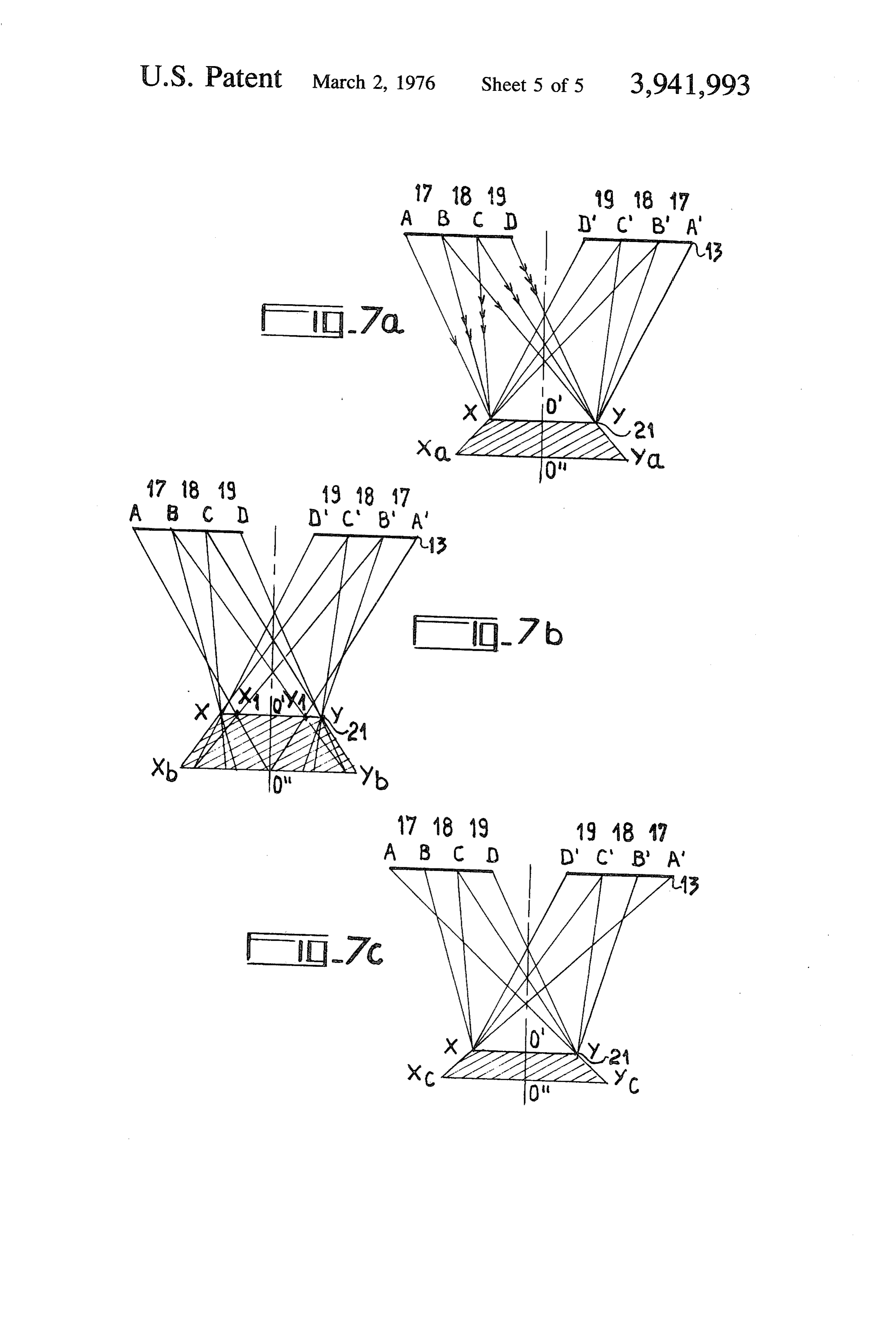
FIGS. 7b and 7c, diagrams of the paths of the case of three characteristic configura 5 of centre O', the width of which may be adjusted by means of the angles of the prisms. Only one source 1 is tions. FIG. , and 2, which were discussed above, relate to shown but it is understood that there may be a number of sources each of which is assigned to one annular a prior FIG.
art illuminating device.
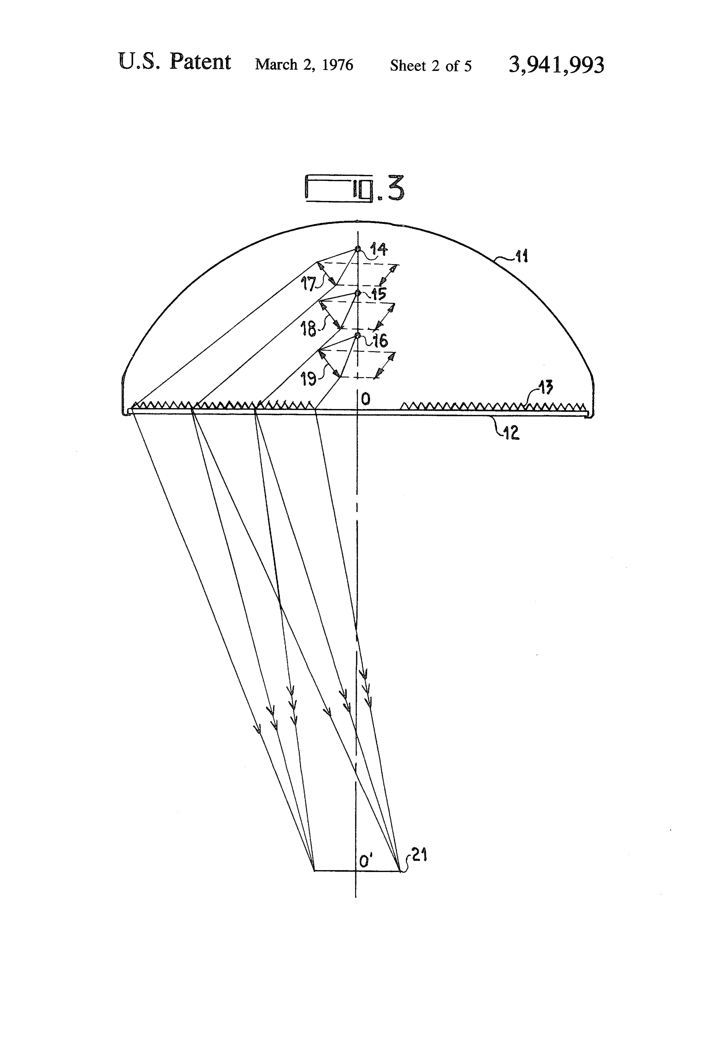
3 is a diagrammatic view, in axial cross-section, band consisting of a number of concentric prisms. 40 of a device according to the invention. The device This arrangment is unsatisfactory since the illumina forms a body of revolution about axis O, O'. A bell tion on the operating field is insufficiently uniform.
In FIG. 2 is shown a diagram of the illumination of plate 12,cover shaped
11 supports a transparent, flat circular plastic material for example, the centre of the field as a function of distance from its centre O'.
Assuming that the operating field requires an illumina 45 which is O and which supports a prism assembly made up from a plurality of juxtaposed rectilinear prisms 13.
tion of 50,000 lux, it can be seen that the illumination at the centre will easily reach twice this value, i.e., sources this
Above
plate 12 are secured one or more light 15 and 16, which are generally formed by 100,000 lux. It is even possible that at one very small miniature iodine filament-lamps. The luminous flux point, one smaller than a light meter is capable of sens emitted by the source or sources is concentrated by an ing, the illumination will be even more intense. The 50 equal number of toroidal optical systems 17, 18, 19 reason for this phenomenon can be understood; the onto prisms 13.
circular prisms reflect all the rays towards the centre FIG. 4 shows the assembly of prisms 13 in plan. It can and in particular the centre receives all the luminous be seen that the individual prisms are straight and are flux reflected by a certain prism, as indicated by refer grouped into a certain number of sectors. Twelve sec ence numeral 6 in FIG. 1. In general terms, if R is the 55 tors are shown but, in fact, their number can be greater. radius of circular prism 7 whose centre is O and r is the The prisms are so orientated as to receive the luminous distance between the centre O' and the point 8 of the flux originating from the toroidal optical systems per field onto which is reflected the beam which strikes the pendicularly to their faces. The light rays enter the said prism, the illumination at point 8 would be a func prisms, are totally reflected by the opposite face, and tion of the ratio R/r. It can thus be seen that the illumi 60 are refracted by the exit face. The orientation of the nation at centre O' should theoretically be infinite. This prism and their apex angle varies from one prism to non-uniformity also results in an abrupt drop in illumi another to allow them to reflect the rays in the desired nation outside the field. In this case the field-width EF direction. In practice, the angles of a number of adjoin was 70 millimeters and at twice the distance away from ing prisms are sufficiently similar in size to enable the the centre O', at point G and H, the illumination was 65 whole of one prism group to have the same apex angle, practically zero. which simplifies machining. In the left-hand part of The objet of the invention is to provide an illuminat FIG. 3 is shown a set of beam paths. The angles of the ing device which employs concentrating prisms and in prisms are so calculated in this case that the beam
Page 8
emanating from each source is reflected onto practi tent of the field, i.e., is 45,000 lux at the centre and cally the whole of the field 21 of centre O', but it is 40,000 at the edges. Another advantage of this system understood that the angles may be so calculated as to is that it extends illumination beyond the edges of the enable the beam to be reflected onto different areas of field. The slope of the curve representing illumination the field, such as smaller areas which partially overlap. 5 is smaller at points K and L in FIG. 6 than at points E FIG. 5 illustrates the beam paths in greater detail. It and F in FIG. 2, which is to say that illumination at the is assumed that the light originates from a single point outer fringes of the field falls less swiftly with straight source situated at O. In actual fact the angular extent of prisms than with circular prisms. the beams from the toroidal optical systems is small, The purpose of this device is principally to illuminate being of the order of 5°, due to the fact that the sources 10 operating fields. In this case the problem is not simply are not point-sources, but the characteristics of the to illuminate an area, in such a way as to avoid shad beam paths are similar. A prism sector AA', DD" as ows, but also to illuminate a cavity and in particular its shown in FIG. 4 is shown in perspective. The angles of walls. It is therefore important that the light beams the prisms are so calculated as to allow the light to be 15 should strike the field at the most oblique angle possi reflected over substantially the whole area of the field ble.
21. It can be seen that the projection of sector AA' DD' Furthermore, the oblique angles at which the light onto plane 21 is substantially a trapezoid aa', dd'. If a beams particular prism is considered, whose reflecting face makes itarenecessary concentrated onto the surface of the field
BB' CC' directs light towards the centre of field 21, it given distance fromforthethefield device to be positioned at a in order to obtain the
can be seen that the projection of this face onto the desired illumination. If this optimum field is a quadrilateral bb', cc' and that a point M for parted position is de from, the light spot increases in example, which is situated at the centre of the crest BB" detriment of illumination. For ease of operation,area, to the of the prism, redirects the light onto a point m situated desirable that the beams should be as little obliqueit asis at the centre of bb'. If it is assumed that point m is 25 possible so that the distance at which the device is used situated at the centre O' of field 21, it can be seen that can be varied whilst still providing sufficient illumina illumination in the vicinity of point m is equal to the tlOn.
illumination over the whole of the quadrilateral bb'cc'. These two contradictory requirements make a com If, while still that point in is situated at centre O', the prisms were arcs of a circle of centre O, instead of promise necessary. An advantage of the invention, being straight, the points B and B' situated on the 30 which makes it possible to orientate the reflection of same crest as M would both focus onto point O', each prism in any direction whatsoever without causing irregularities in the distribution of the light over the whereas the sector AA, DD", assuming it to be of field in a non-uniform manner, is that it allows a large the same size as in the case of the straight prisms, would be projected onto field 21 in the form of sub 35 number of reflective configurations. stantially two sectors a... o' a ''', and d' o' d' FIG. 7 shows three typical configurations diagram which are opposed at the apex and whose angular matically.
extent corresponds to that of sector AA', DD'. FIG. 7a relates to the configuration in FIG. 3. In it are It can be seen that in the latter case, all the luminous seen three groups of prisms AB, BC, CD together with flux reflected by prism BB", CC" is concentrated on a 40 their symmetrical counterparts A'B', B'C', C'D'. sector 22 which is marked in black on the figure, the These receive three beams 17, 18 and 19 from three sector being of the same angular extent and having a sources which are not shown. Each beam is reflected radius corresponding to the width of the prism, and it onto the whole of field XY. When field XY is moved can also be seen that all the flux which strikes the prism towards or away from the plane of prisms 13, illumina in the vicinity of the crest BB" is concentrated onto tion decreases as the illuminated area increases. It has point O', thus giving a theoretically infinite illumina 45 been found by experiment that illumination remains tion at this point. adequate over the whole of the field down to a level X. In the device according to the invention, each sector Y for instance. There is also another limit between of straight prisms produces on field 21 a quadrilateral field XY and the device at which illumination is ade area of illumination similar to quadrilateral aa', dd' but 50 quate but a position for the field above line XY would which is shifted by an angle equal to the angular extent not appear suitable for use, because of the fact that of the sector. It can be seen that this superimposition of walls normal to the plane of the field at points X and Y the various angularly shifted quadrilaterals improves would then, in theory, receive no luminous flux, as can even further the uniformity of illumination. be seen from the path of the beams. The permitted Another advantage of this superimposition of the 55 variation in the distance between the operating field quadrilateral areas of illumination becomes apparent and the device is thus delimited by points O' and O'. when an opaque obstruction masks the field. If it is The frusto-conical area in which illumination is ade assumed that the obstruction masks one sector of quate is shown by a hatched cross-section XY X Y. prisms, in the case of the circular prisms the illumina and the upper and lower bases of this area have as their tion in the corresponding sector of the field is reduced 60 centres O' and O'. Points situated within walls X X by half, where as in the case of straight prisms the and Y Y, thus receive luminous flux from at least one illumination over the whole area of the field is reduced of the beams 17, 18 or 19. The lines XX and YY are by a fraction equal to the reciprocal of the number of situated on the straight lines B'X and BY which corre prism sectors since each of the sectors illuminates the spond to the outer edge of the most divergent beam. whole of the field. 4. Attempts have however been made to increase the Like FIG. 2, FIG. 6 shows a diagram of the illumina distance O'O' in order to make the device easier to use tion of a field, but in this case it is one illuminated by a by reducing the accuracy with which it needs to be set device according to the invention rather than by a prior up. In FIG.7b is shown a beam path in which beams 18 art device fitted with circular prisms. It can be seen that and 19 are still reflected onto the whole of field XY but illumination is practically constant over the whole ex in which the outside beam 17 is reflected onto a central
Page 9
portion X, Y of field XY. It can be seen that, due to What is claimed is:
this fact, the useful volume XY X, Y is delimited by 1. An illuminating device intended to illuminate the segments XX, and YY of straight lines CXX and operating field of an operating table with substantially CYY, which are less divergent in relation to the axis of uniform intensity comprising:
the device than the straight lines B'XX and BYY in 5 at least one light source emitting light beams, the previous configuration. The luminous flux is thus a toroidal optical system, adapted to receive said less divergent and it can be seen that the distance O'O' light beams, and said light source being located at which illumination on area X, Y, is still adequate is substantially on the axis of and above said toroidal greater than the distance which separated planes X, Y, 10 system, and XY in FIG. 7a. Configuration 7b is better suited to a plate member having a center and so located be rapid deployment than configuration 7a but it provides neath said toroidal system that said light beams, weaker illumination of the vertical walls of a cavity. passing through said toroidal system, impinge FIG. 7c is a diagram of a configuration in which the thereon, inside beams 18 and 19 are still reflected onto the a prism assembly on said plate, said assembly being whole of field XY as in the previous configuration but 15 made of a plurality of juxtaposed straight prisms, in which the outer beam 17 is reversed for the purpose each said prism having an axis and at least one of directing it toward field XY. The prism situated at A reflective face, each said axis of each said prism reflects the light onto the edge Y of the field, the prism being parallel to a plane, said prisms combining in situated immediately inwards of prism. A reflects light 20 a plurality of sectors, the vertices of which are onto a point situated next to Y in the direction of ex substantially located in the center of said plate, tremity X, and so on in the case of all the prisms until the light source, the center of said plate and the cen B is reached where the light is reflected onto X. ter of said operating field being substantially In this case it can be seen that the useful volume aligned and said light beams from said light source XYXY is much more divergent than in previous cases 25 impinging on said operating field through said to and that the distance O'O' between planes XY and roidal system and said prism assembly. X-Y is much smaller. Unlike configuration 7b, config 2. An illuminating device as claimed in claim 1, in uration 7c calls for the device to be accurately set up which said sector has an angular extent of such a value but provides far stronger illumination of the vertical that the reflected light beams form on said operating walls. field a trace having a width which is substantially the There is a large number of configurations and the 30 same as that of the field.
three above are only given as examples. This shows the 3. An illuminating device as claimed in claim 1, in advantages of using straight prisms in the device, which said reflective face of each prism is so orientated thereby allowing the light to be distributed in the de as to reflect the light onto a predetermined part of the sired way over the field area, without the necessity for 35 field.
making allowance for the focussing of the light at the 4. An illuminating device as claimed in claim 3, in centre of the field. which the said straight prisms situated on the outer In all the foregoing it was assumed that the device periphery of the prism assembly reflect the light onto was fitted with three light sources but it is understood the opposite outer section. of ckthe ckoperating field. that there may be any number of sources. 40
Provenance
- Collection
- Cited prior art
- Original PDF
- patentimages.storage.googleapis.com →
- Filed
- 1974-10-09
- Pages
- 9
- Method
- pdftotext (the PDF's own text layer) + pdftoppm 300dpi page scans
- Source
- Google Patents bibliographic record
- Granted
- 1976-03-02
- Inventors
- Jean Hubert; C G R ALEXANDRE
- Transcribed from
- patentimages.storage.googleapis.com →