patent · US1421506
Headlight
4 July 1922
Page 1
Drawing sheet — no readable text.
Page 2
UNITED STATES PATENT OFFICE.
ALEXANDER. S. LIMPERT, OF PITTSBURGH, PENNSYLVANIA.
1,421,506. Specification of Letters Patent. Patented July 4, 1922. Application filed July 17, 1920. Serial No. 396,895.
To all whom it may concern; quately illuminate the road ahead, but which Be it known that I, ALEXANDER. S. LIM will not produce an objectionable glare and PERT, a citizen of the United States, residing will not blind or confuse the driver of an ap at Pittsburgh, in the county of Allegheny . proaching car. 60 and State of Pennsylvania, have invented A further object is to produce a headlight new and useful Improvements in a Head in which the source of light is adjustably light, of which the following is a specifica mounted so that the reflected rays projected tion. from the headlight may be properly focused This invention relates to improvements in by adjustment of the position of the source 65 O automobile headlights and has for its par of light relatively to the reflecting surfaces. ticular object the production of a simple, Still another object is to provide a head durable and economical headlight that is light which will be strong and durable in capable of reflecting rays from the Source of construction, one which can be manufactured light forward to a maximum distance but at a reasonable cost, and one which will not 70 5 with a minimum amount of glare, all as be subject to displacement of the parts, and hereinafter fully described. which will not be easily broken or injured. It is highly desirable in lights of this Other objects and many of the attendant character and particularly in automobile advantages of this invention will be readily lights that the light rays be directed upon appreciated as the same becomes better 75 20 the road in front of the machine for a understood by reference to the following de considerable distance without producing a Scription when considered in connection with bright glare, which is confusing to the driver the accompanying drawings. of an approaching machine, and to reduce Referring to the drawings:
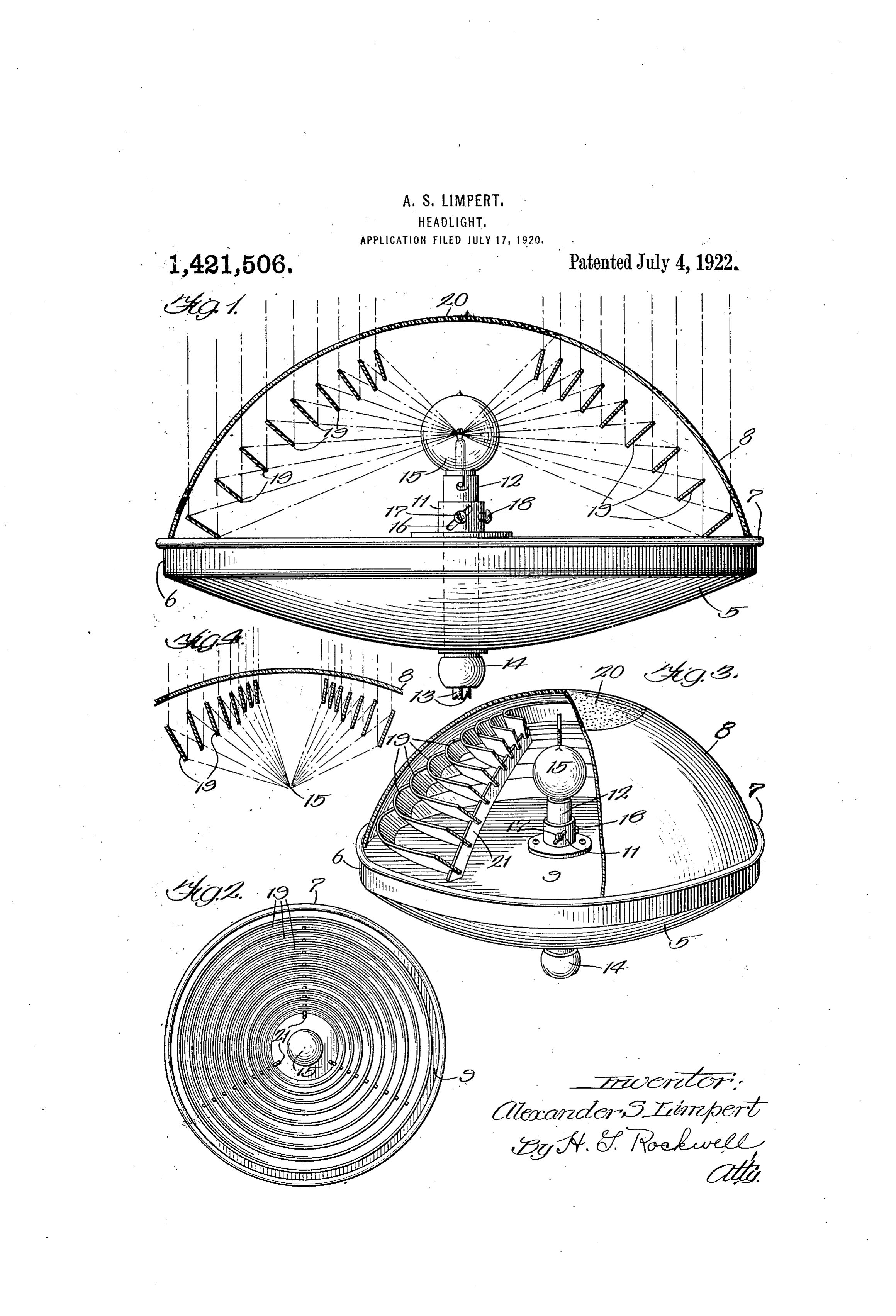
or obviate this glare as much as possible, it Fig. 1 is a side view partially in trans 80 25 is desirable that the light rays be projected yerse section of a headlight embodying my in substantial parallelism below the horizon invention;
tal plane of the driver's eyes of an approach Fig. 2 is a face view thereof with the ing machine. This means, of course, that weather glass removed to more clearly show the rays emanating from the light should the arrangement of the reflectors; 85 30 not be permitted to project above the plane Fig. 3 is a perspective view of the head of the light itself. light, certain parts being shown in section; It has heretofore been proposed to Secure and this result by the employment of parabolic Fig. 4 is a fragmentary diagrammatic reflectors, which are designed theoretically view showing a slightly modified form of 90 35 to reflect and project the rays emanating my invention.
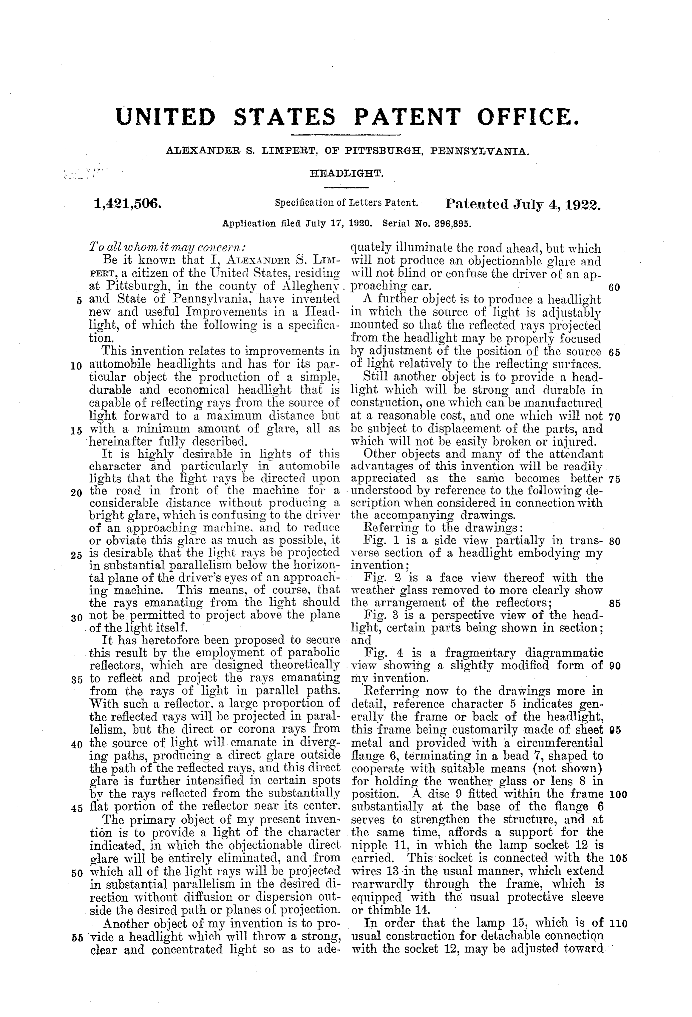
from the rays of light in parallel paths. Referring now to the drawings more in With such a reflector, a large proportion of detail, reference character 5 indicates gen the reflected rays will be projected in paral erally the frame or back of the headlight, lelism, but the direct or corona rays from this frame being customarily made of sheet 95 40 the source of light will emanate in diverg metal and provided with a circumferential ing paths, producing a direct glare. Outside flange 6, terminating in a bead 7, shaped to the path of the reflected rays, and this direct cooperate with suitable means (not shown) glare is further intensified in certain spots for holding the weather glass or lens 8 in by the rays reflected from the substantially position. A disc 9 fitted within the frame OO 45 flat portion of the reflector near its center. substantially at the base of the flange 6 The primary object of my present inven serves to strengthen the structure, and at tion is to provide a light of the character the same time, affords a support for the indicated, in which the objectionable direct nipple 11, in which the lamp socket 12 is glare will be entirely eliminated, and from carried. This socket is connected with the OS 50 which all of the light rays will be projected wires 13 in the usual manner, which extend in substantial parallelism in the desired di rearwardly through the frame, which is rection without diffusion or dispersion out equipped with the usual protective sleeve side the desired path or planes of projection. or thimble 14.
Another object of my invention is to pro In order that the lamp 15, which is of 110 55 vide a headlight which will throw a strong, usual construction for detachable connection clear and concentrated light so as to ade with the socket 12, may be adjusted toward.
Page 3
or from the frame 5 for the purpose of front is set at a more acute angle with re focusing the light, the Socket, 12 is adjust spect to a transverse plane parallel with the ably connected with the nipple 11. Whiie disc 9, these angles being such that the rays any preferred method of connection may be when reflected are all projected forwardly utilized, I have shown in the present in in substantial parallel paths, as illustrated stance the nipple 11 as equipped with an in Fig. 1.
inclined slot 16, through which a lug oi" Furthermore, it will be observed that as screw 17 secured to the socket projects. By the reflectors approach the front of the turning movement of the socket, it is ad headlight, they are disposed progressively 10. iusted inwardly or outwardly with respect nearer together in order to preclude direct 75 to the nipple and when the requisite ad emanation of rays between then so that the justment has been secured, the socket is corona rays heretofore mentioned are cut off locked in adjusted position by means of a and reflected. These reflectors may, if de set screw i8. It should be noted at this sired, be continued practically to the front 5 point that the disc 9, instead of presenting of the lamp, a close approach to such ar 80 a bright surface having light reflecting rangement being shown in Fig. 4, but since properties, is inert, and in the preferred con the direct rays in front of the source of struction of my light, is painted black so light emanate substantially in the desired that no light is reflected therefrom. direction without reflection, the employment 20 The reflection of the light rays entrating of a large number of these very small reflec 85 from the source of light 15, so that these ÉOr's does not justify the expense, and in rays will be projected from the headlight order therefore, to preclude the glare result in the desired direction and in Substantial ing from the rays which are not intercepted parallelism, is effected by a series of arrow by reflectors across a small arc at the front 25 frustoconical reflectors 19, arranged con of the lamp, I prefer to sandblast or other 90 centrically with respect to the lamp base. wise roughen the front of the weather glass and disposed in spaced relation from front 8 over this area, as indicated by reference to rear of the light, the reflectors being character 20. This roughened area will ob from rear to front of progressively dimin viate the glare, and for all practical pur 30 ishing diameters, so that, as will be ap poses, is substantially as effective and con 95 parent from the drawings, the largest re siderably cheaper than the employment of flector is disposed at the rear while the 5, large number of closely set reflectors of smallest is disposed in front. These reflec very Small diameters.
tors are mounted upon suitable supports 21, Since the back of the lamp, or in other 35 preferably three in number. to which they words, the disc 9 is inert, it will be mani 100 are securely attached by soldering or other fest that no rays of light strike the reflectors wise, to form a substantial and rigid struc except those emanating directly from the ture. Preferably, the supports 27 are slotted Seirce of light. Consequently, the location to accommodate the inner edges of the re of this source being known and the source 40 flectors, thus adding to the rigidity of the itself being capable of adjustment as pre 05 structure, and the assembled construction is viously explained, each ray is intercepted then secured to the disc 9 in any suitable and accurately reflected in the desired direc manner so that it will be retained in posi tion, and no fugitive rays, such as are tion concentrically with the lamp, and will present in parabolic reflectors as the result 45 be held against displacement or rattling of double reflection, are produced in my 10 when in use. in proved construction, and consequently, no It will be observed from Fig. 1 that the rays are delivered in an undesirable direc reflectors are arranged in overlapping re tion, but each ray is accurately projected in lation so that when viewed from the inside. the direction that it should travel. Should 50 the inner edge of each successive reflector the lamp be positioned too far forwardly, L5 from rear to front slightly overlaps the the light rays will be projected in diverging outer edge of the next rearwardly adjacent Baths. and should it be too far rearwardly, reflector, and when viewed from the front, the rays will be projected in converging the outer edge of each successive reflector paths which will ultimately cross and then 55 from rear to front slightly overlaps the diverge, but by means of the adjustment 20 inner edge of the next rearwardly adja provided, the lamp can be accurately posi cent reflector. tioned so that all of the rays will be pro With this construction, it will be mani jected in substantial parallelism and in the fest that the light rays emanating from the desired direction.
60. source of light are all intercepted by the It is believed that my invention, one mode 25 reflectors so that no light except on a short of its construction, and many of its inher arc directly in front of the lamp is per ent, advantages will be understood and ap mitted to escape unreflected between adja preciated from the foregoing without fur cent reflectors. It will also be observed ther description, but it should be manifest 65 that each successive reflector from rear to that the structural details illustrated and 30
Page 4
described are capable of considerable modi be projected by said source to points inter fication, without departing from the essence mediate the front and rear reflectors with of the invention as defined in the following out being reflected forward by one of said
I claim: 3. An automobile headlight comprising a 1. An automobile headlight comprising Source of light, a series of annular reflectors a source of light, a series of concentrically of progressively diminishing diameters ar arranged annular reflectors adapted to ranged in overlapping relation with respect 40 reflect in substantial parallelism intercepted to each other so that no direct rays from 10 light rays emanating at various angles from the source of light can pass between ad said source, said reflectors being of progres jacent reflectors without being reflected sively diminishing diameters from the rear thereby, the front reflector being disposed to the front of said headlight and each be in advance of said source of light and the 45 ing respectively disposed at different angles rear reflector being disposed behind the 15 with respect to said source of light and the rearmost point of said source of light and front reflector being in advance of said light said reflectors each extending rearwardly a light.the rear reflector being behind said reflector and distance less than that of the next adjacent
2. An automobile headlight comprising a 4. A headlight comprising a series of con 20 source of light, a series of concentrically ar centrically disposed annular reflectors, a ranged annular reflectors adapted to reflect source of light comprising an electric light in substantial parallelism intercepted light bulb disposed axially within such series of rays emanating at various angles from said reflectors, the outermost reflector being in 55 source, said reflectors being of progressively front of said light bulb and the rear reflec 25 diminishing diameters from the rear to the front of said headlight and each being re said tor being to the rear of said light bulb and spectively disposed at different angles with having reflectors, when viewed from the front, the outer edge of each successive respect to said source of light, the front re reflector from rear to front slightly over 60 flector being in advance of said light and lapping the inner edge of the next rear 30 the rear reflector being behind said light wardly adjacent reflector. and the arrangement and size of said re flectors being such that direct rays cannot ALEXANDER. S. LIMPERT.
Provenance
- Collection
- Cited prior art
- Original PDF
- patentimages.storage.googleapis.com →
- Pages
- 4
- Method
- pdftotext (the PDF's own text layer) + pdftoppm 300dpi page scans
- Source
- Google Patents bibliographic record
- Granted
- 1922-07-04
- Transcribed from
- patentimages.storage.googleapis.com →