patent · US4074704
Process of and apparatus for solar heating and the like
21 February 1978
Page 1 — bibliographic record
350 as 4.52 SR
United State I 4,074,704 Gellert 5 Feb. 21, 1978 (54) PROCESS OF AND APPARATUS FOR (56) References Cited SOLAR HEATING AND THE LIKE U.S. PATENT DOCUMENTS 937,013 10/1909 Severy ................................. 126/271 76 Inventor: Donald P. Gellert, Box 37, R.F.D. 1, 3,982,527 9/1976 Cheng et al.......................... 126/271 Plymouth, N.H. 03264
Primary Examiner-Kenneth W. Sprague (21) Appl. No.: 691,092 Attorney, Agent, or Firm-Rines and Rines, Shapiro and Shapiro 22 Filed: May 28, 1976 57 ABSTRACT This disclosure is concerned with the collection and 51 Int. Cl”................................................ F24J 3/02 concentration of solar ray energy and the like through 52 U.S. C. .................................... 126/270; 126/271; optimal use of prismatic and reflective concentration
Page 2
Drawing sheet — no readable text.
Page 3
Drawing sheet — no readable text.
Page 4
the critical prismatic magnification and solar concentra
PROCESS OF AND APPARATUS FOR SOLAR tion manner underlying the techniques of the invention, HEATING AND THE LIKE but rather have had other refraction uses of the type The present invention relates to processes or methods described, for example, in the following patents: Bas of and apparatus for solar heating and the like, being. 5 quin - U.S. Pat. No. 586,211; Mygatt - U.S. Pat. No. more particularly directed to improvements in the col 821,310; Guth - U.S. Pat. No. 1,294,900; Rolph - U.S. lection and concentration of solar and similar energy. Pat. No. 2,015,235; Merton - U.S. Pat. No. 2,248,638; Man has long dreamed of harnessing solar energy for and Eibon - U.S. Pat. No. 2,558,373.
his effective utilization; and the art is replete with pro A principal object of this invention, accordingly, is to posals for absorbing, storing and using the sun's rays, O provide a new and improved process or method of and embodying many types of absorber systems. Among the apparatus for solar heating and the like, particularly early United States Letters Patent bearing upon such involving maximally concentrating the sun's rays schemes are the following: Severy - U.S. Pat. No. through level prismatic and reflection concentration, 496,959; Paine-U.S. Pat. No. 509,392; Davis - U.S. Pat. that obviate the above-mentioned disadvantages of No. 629,122; Walker - U.S. Pat. No. 705,167; Cunniff - 15 prior art proposals and provide a relatively inexpensive, U.S. Pat. No. 819,342; Severy - U.S. Pat. No. 937,013; universal construction that, additionally, eliminates the Rountree - U.S. Pat. No. 1,003,514; Trosper - U.S. Pat. need for movable tracking systems, where not desired No. 1,325,596; Vinson - U.S. Pat. No. 1,673,429; Cline - or not feasible.
U.S. Pat. No. 2,202,756; and Modine - U.S. Pat. No. Another object of this invention is to provide a novel 2,274,492. These proposals involve variations in ab 20 solar collector and system that is simple in construction, sorber materials and constructions, liquid and other and can be installed and maintained in the home or transfer assemblies, gear-driven mechanisms for track similar area without highly skilled installers. ing the sun's position, and related concepts that, while In summary, from one of its important aspects, the theoretically operative, were too complex, costly or invention embraces a process of collecting solar energy specialized to permit of general commercial use. 25 by impinging the radiation upon a plurality of succes Other attempts to utilize solar energy were directed sive radiation-transmitting surfaces each oriented at an towards improvement in solar radiation concentration acute angle to an adjacent plane; refracting the radiation by reflection and optical magnification, primarily in so impinged upon each surface in the regions between volving reflectors and lenses and combinations of the the same and the adjacent plane; directing the refracted same as described, for example, in the following United 30 radiation upon a collecting surface located at a prede States Letters Patent: Wideen - U.S. Pat. No. 683,088; termined region behind said plane; adjusting the said Himalaya-U.S. Pat. No. 797,891; Harris - U.S. Pat. No. acute angle of orientation with reference to the refrac 2,625,930; Von Brudersdorff-U.S. Pat. No. 2,859,745; tion index in said regions and within limits such that the Cotton et al. U.S. Pat. No. 2,987,961; Macauley - U.S. refracted radiation is effectively concentrated to pro Pat. No. 3,085,565; Hunt - U.S. Pat. No. 3,118,437; Fal 35 vide greater energy per collecting surface area than the bel - U.S. Pat. No. 3,179,105; Lessley - U.S. Pat. No. radiation energy per unit area upon the first named 3,229,579; Mertz - U.S. Pat. No. 3,469,902; Trombe surfaces, thereby amplifying the energy at the collect (French) - U.S. Pat. No 1,165,672; Popoff (German) - ing surface; and absorbing the energy at the collecting U.S. Pat. No. 394,232; and Baulino (Italian) - U.S. Pat. surface. Preferred details and constructional features No. 370,365. The cost, complexity and space require 40 are hereinafter set forth.
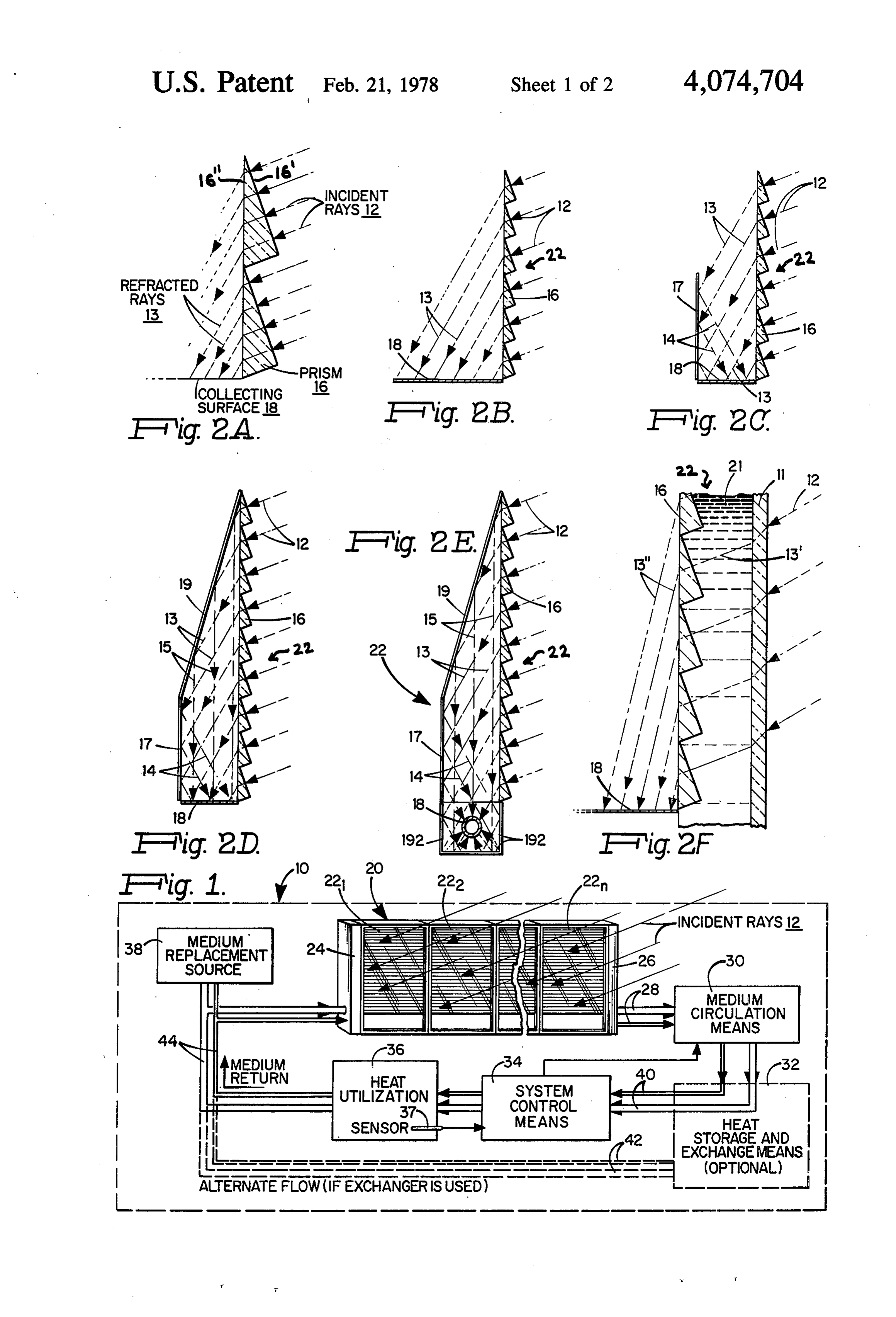
ments of such constructions, and the various degrees of The invention will now be described with reference inefficiency and impracticability there-involved have to the accompanying drawings FIG. 1 of which is a also prohibited the use of such reflector and/or lens combined isometric and block diagram of a solar heat systems for general use. ing system embodying the invention; More recent proposals in the use of lenses, including 45 FIG. 2B is a cross-sectional view of a preferred pris Fresnel lenses, and reflectors have provided techniques matic concentrating array for use in the system of FIG. for concentrating solar energy to a level of high heat 1;
intensity; as described in United States Letters Patent of IG. 2A is an enlarged fragmentary section of FIG.
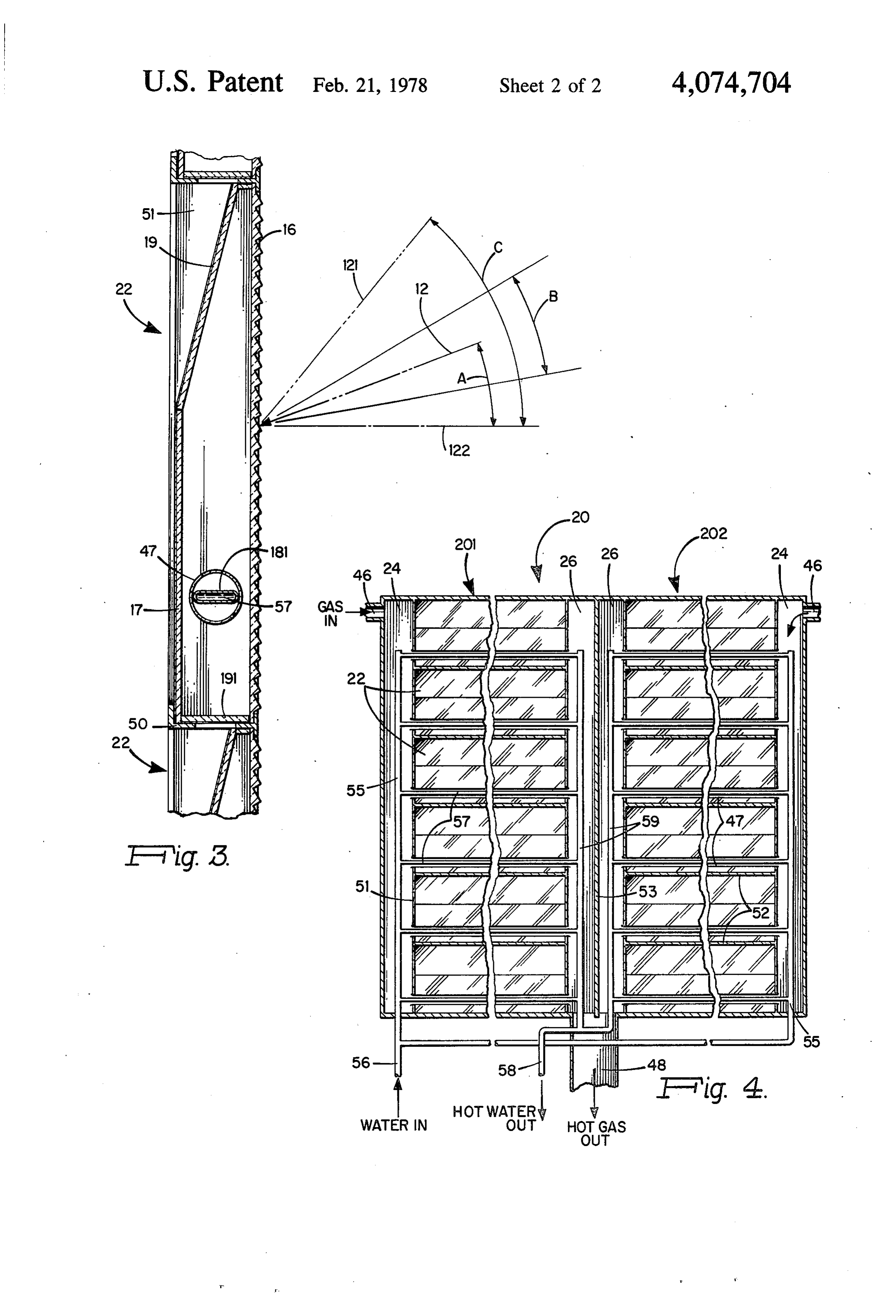
No. 3,171,403; Culling - U.S. Pat. No. 3,182,654; 50 FIG. 2C - F are similar views of modified collector Dickinson - U.S. Pat. No. 3,407,122; Weiner U.S. Pat. constructions employing arrays similar to FIG. 2A and No. 3,467,840. While heat concentration at tempera B;
tures of thousands of degrees has been claimed, and FIG. 3 is a view similar to FIG. 2E, illustrating sev while at the present state of the art, it is possible to track eral stacked arrays in an installation and showing angu the sun for the direct utilization of its energy, to concen 55 lar coverage; and trate the energy to high intensity, and to transfer and FIG. 4 is a front elevation view of a two-dimensional store the same, such systems unfortunately involve ex system of vertically and horizontally stacked and inter pense and complexity that keep them well out of the connected prismatic collector array systems. reach of the general public for its home and related Referring to the overall system 10 of FIG. 1, the total heeds. It is, indeed, to the solution of the problem of 60 solar collector is designated at 20, comprising individual utilizing solar energy for practical private home and collector arrays 22, numbered 221, 22. . . . 22. The office use and the like that the present invention is par incident solar (or similar) rays 12 enter the collectors 22, ticularly directed. the details of which are later discussed, resulting in Underlying the invention is the discovery of highly concentrating the rays at an internal collecting surface effective solar concentration through a novel com 65 as hereinafter explained, and enabling heating of a liquid pound of prismatic magnification and reflection with or other medium circulated in pipes, conduits or lines 28 optimum geometric placement. While prisms are well emerging from the right-hand end 26 of the collector known devices, they have not heretofore been used in system 20 in rather conventional fashion, under the
Page 5
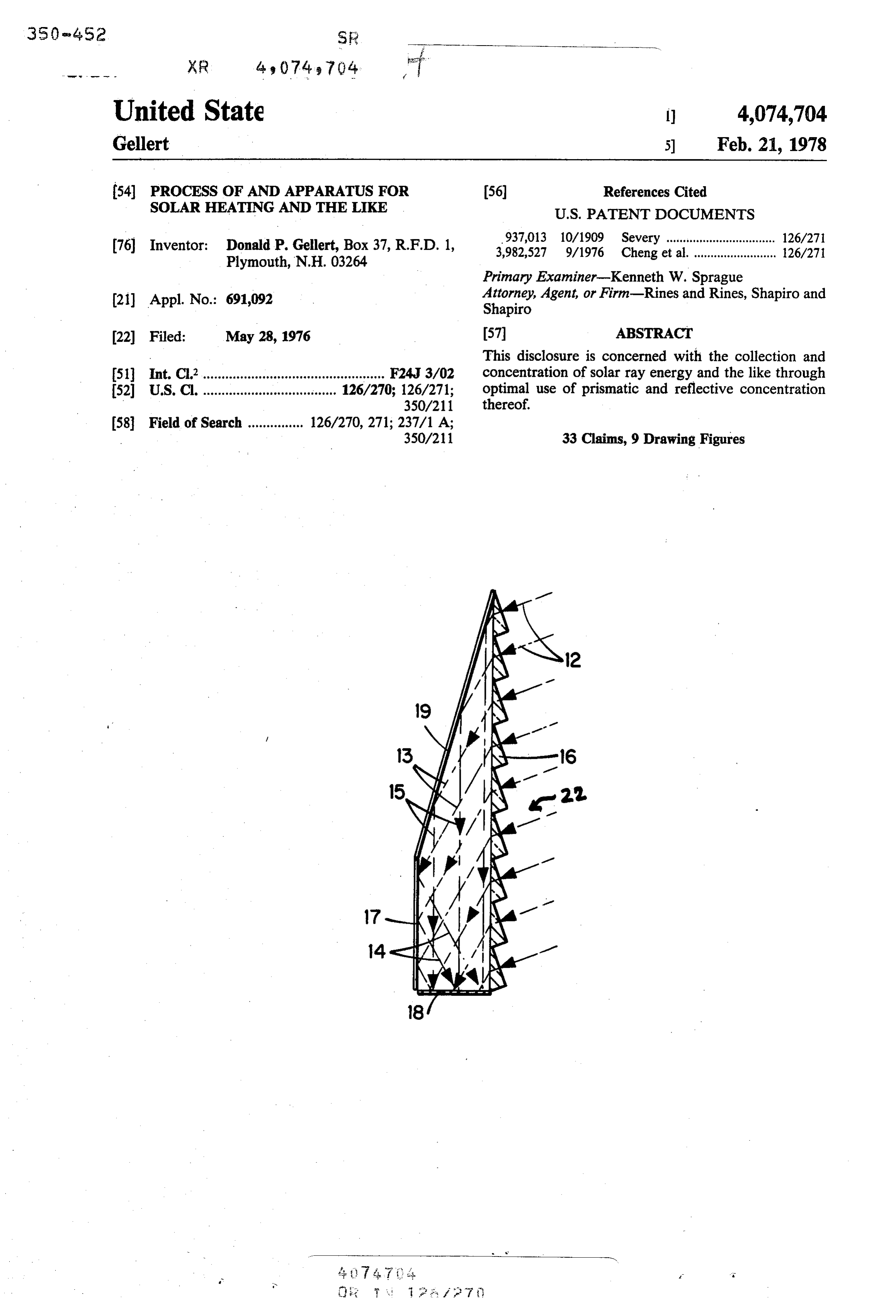
action of a pump or other circulating means 30. The doubled height, such energy concentration may be thus circulator 30 may be controlled by a conventional sys increased by another approximate factor of two. tem monitor control 34 responsive to a heat sensor 37 If, moreover, a second reflector 19 is added, inclining associated with a utilization system generally indicated upward at half the angle of refraction to direct the at 36. The circulator 30 may also communicate by lines refracted rays 13 incident thereupon downward at 15 40 with conventional heat storage and exchange means upon the collecting surface 18, as shown in FIG. 2D, 32, if used, with alternate flow paths 42 employed in the the array height can be further increased with corre event of such heat exchange, as is well known. A source sponding proportional increase in concentration at the of fluid or other medium replacement 36 may be cou absorber collecting plane or surface 18. Clearly curved pled to the medium return lines 44 entering the left-hand 10 as well as planar reflectors may be used, including re end 24 of the collector system 20. Clearly, other well flectors of parabolic contour.
known circulation systems may also be employed, the The system of FIG. 2D is indeed employed in the invention being concerned with the novel solar collec embodiment of FIG. 2E wherein the concentrating tion and concentration technique and apparatus and not surface 18 is shown in the practical form of a fluid-car the particular circulation or utilization system associ 15 rying tube serving as a black body absorber and con ated therewith. tained in a channel of Fresnel concentrating reflectors Turning to that novel collection and concentrating 192 which further focus the downwardly refracted and technique and apparatus, the forms of collector arrays reflected-refracted rays with higher concentration of 22 illustrated in FIGS. 2A-F and FIGS. 3 and 4 operate heat than with the narrow planar absorber surfaces 18 upon the preferred principle of substantially vertically 20 of FIGS. 2A-D.
oriented, flat-plate, concentrating non-tracking low The embodiments of FIGS. 3 and 4 illustrate practi cost-material arrays or pluralities of small-angled paral cal modular construction embodiments 22 of the system lel prisms 16. The vertical or near vertical orientation of FIG. 2D with the absorber 18 shown at 181 as a minimizes umbrageous, collection-nullifying effects of tubular element 57 enclosed in a Pyrex enclosure 47, foreign matter accumulation. The flat-plate concentrat 25 and with the unit having a base 191. In FIG. 4, the ing array has the advantages of easily generated and system 20 is shown embodying a pair of collector as architecturally useful surfaces with minimization of semblies 201 and 202 of vertically stacked units of the insulative areas. As shown in FIGS. 2A and B, incident type described in connection with FIGS. 2E and 3, for rays 12 of the sun impinge upon the protruding stag example, and adapted for the heating of both gas and gered front surfaces 16 (FIG. 2A) of the successively 30 water. Gas enters through inlet 46 and exits at 48, being vertically stacked small angle prisms 16, with the front heated while in manifolds 24 and 26 from the radiation surfaces 16" critically oriented forward at an acute angle collimated by individual collector arrays 22. The water with respect to the vertical plane, as later more fully entering at water valve 56 passes through water jackets delineated. The rays are transmitted through the front in manifold 55, through transfer tubes 57 and water surfaces 16" of each of the prisms 16 and are similarly 35 jackets in manifold 59, exiting at valve 58. refracted by the similar prisms as they respectively pass If desired, moreover, additionally to enhance perfor through the region of each prism, emerging as refracted mance, an auxiliary chamber 11-21 may be used for rays 13 at the vertical rear surfaces 16" of the prisms 16. ward of the prism array 16 filled, for example, with By appropriate selection or adjustment of the acute transparent media such as liquids of appropriate refrac angle orientation of the front prism surfaces, 16', the tion indices (to effect a desired incidence 13' and ulti included acute angle of the prisms and the refractive mate refraction 13") thus to yield a reasonably efficient index of the material thereof, the refracted rays 13 can static system that requires neither daily nor seasonal be caused to be concentrated closer together than the adjustment to accommodate for solar movements. The incident rays 12, as shown, providing greater energy medium 21 may also comprise other optionally refrac per collecting surface area at 18 than the radiation en 45 tive materials such as prisms that could receive rays 12 ergy per unit area upon the front prisms surfaces 16', from widely different angles including, for example, thereby amplifying the energy at the collecting surface normal to the surface, and would refract the same to 18, which may be a "black body' absorbing surface. provide the incidence 13' required by the array of Though later discussed in detail, appropriate selection prisms 16.
of prism refractive index and acute angle may result, for 50 The wide diversity of application and modification example, in doubling the energy concentration at a thus feasible with the present invention permits it to be surface 18, of horizontal width about half the height of retrofitted to existing walls or built into new construc the prism array. tions; enables diffused light to pass while concentrating Through the use of this concentrating action on inci direct rays; is installable by unskilled hands though dent radiation by such small-angle prisms, therefore, 55 involving a high technology assembly that can produce inexpensive but highly effective collector arrays 22 may sufficiently high temperatures to service even numerous be constructed embodying one or two dimensional ar industrial packaged boiler applications. Apart from rays or other geometrical configurations, such as annu high technology applications involving a prismatic lar arrays, or sets of arrays as more particularly shown, array of glass, the materials for prism construction can for example, in FIGS. 1, 3 and 4, with the basic building 60 be selected from among the following mass-produced block a simple, thin, transparent vertical sheet of and inexpensive materials: acrylics, such as acrylic stacked parallel prisms 16, say of the order of 25 mils in polyester, poly carbonates, vinyls, cellulosics and eopxy thickness. cast resins. Thermoplastic sheets extrusion-molded by By employing a taller array of prisms 16, a reflector diamond machined aluminum rolls, appropriately 17 may be used rearward of the array, FIG. 2C, and 65 plated with nickel or chrome, may be readily fabricated, extending upward from surface 18 at a position such as as may other engraved, cast or machined arrays. to intercept the concentrated refracted rays 13 and It has been found that, for a material of given optical reflect them at 14 upon the surface 18. With an array of properties, there is a single unique "most efficient' pris
Page 6
matic angle for collecting incident solar energy could readily be automatically effected by any well throughout a heating season, without re-orientation of known photoelectric-controlled servo mechanism the collector array. Otherwise stated, the appropriate mounted on the frame 20 (though not shown in FIGS. selection of prism refractive index and prismatic angle 1 and 4); or, if more elaborate and expensive systems can define the system's "operating window'. The 5 were desired, azimuth and/or altitude well-known prisms have been shown preferably having a substan tracking mechanisms could also be employed. Thus the tially right angle at the forwardly protruding vertex, system of the invention need not be strictly vertically and an angle at the top vertex which is included be oriented in all instances, but may be inclined, as well; tween the front surface 16" and the vertical, and is such that reference to the vertical and horizontal orien hereinafter referenced as the prism or prismatic acute 10 tation herein are to be deemed as references to relative angle. The prism angle in FIGS. 2A-E is equal to the axes or orientations and are generic terms. angle A between the incident rays 12, normal to the Losses encountered with the process and apparatus of front prism surface 16", and the horizontal 122, FIG. 3. the invention by an incident ray include the following: An increase in the prism material refractive index at (1) Reflection loss as the ray 12 enters the front sur any given prismatic angle will increase the collector 15 face 16 of the prism 16- 4% when the ray 12 is normal concentration, but decrease the "operating window'; to the surface 16'. The average is about 6% for heating the converse being also true. Reducing the prismatic season solar azimuths.
angle for a material of given refractive index, moreover, (2) Internal reflection loss at refracting surface 16'- will reduce collector concentration, while extending from 4% to 100% depending upon refraction angle. the "operating window'. These two parameters should 20 About 9.5% average over the coldest portion of the be optimized for the selected cost effective material and heating season in the above examples. application. (3) Front surface mirror absorption loss - 2%. For a prism material of about 1.5 refraction index, a (4) Total reflection from inner and outer surfaces of prismatic angle of about 33.5" was selected for opera collector tube 47, FIG. 3 - 6%.
tion in tests later discussed; though successful paramet 25 (5) Absorption at 18 (181, FIG. 3) - 96% (4% loss). ric analyses have been made for refraction indices in the As the summer Solistice is approached, the angles of range of from about 1.5 to about 1.58 and associated azimuth at dawn and dusk become so large that no light prism angles in the range of from about 27 to about 36. is accepted by a south-oriented collector in the illustra Studies have been carried out with a system of the tive installations previously discussed. Additionally, as type shown in the embodiment of FIG. 3 with a cast 30 the angle of inclination increases beyond the point at acrylic polyester prismatic array 16 of prism refractive which the reflection at the internal refracting surface index 1.50 and with an angle of 17 between reflector 19 (item (2), above) is 100%, no light is transmitted and the and the vertical plane, and having the following struc system 20 becomes a visible light radiation shield. ture and characteristics: The maximum effective collecting area presented Prismatic angle - 33.5" (erected vertically with the 35 normal to the sun by a 600 square foot 33.5 degree collecting surface at a 56.5 tilt angle) prismatic array 22 of the invention (say about 100 Prismatic density - 4.333 per inch of collector concen prisms to the inch) is about 500 square feet. The average trator height normal flux on a clear December day at 43' N latitude, Concentrating mirrors - first surface Mylar is 230 BTU/hour-ft.”, and it persists for 9 hours. This Absorber (at 18) - elliptical water-filled copper calo average flux, corrected for azimuthal projection on the rimeter (Ebanol-C) vertical, south-facing collector, reduces to an effective Vertical collecting area - 345 sq. in. (30 in. height X average 193 BTU/hour-ft. At a collection efficiency of 11.5 in. width) 63.5%, the system can thus be expected to collect and Effective prismatic collecting area - 2 sq. ft. transfer to the absorber coolant a total of 551,497 Absorber area - 48 sq. in. 45 BTU/day, or 13,787 BTU/day/module 22. Series-par Concentration factor, normal ray - 6 alleling of the individual modules 22 may be arranged so Thermally insulated surfaces - none required. that easily attained coolant flow (say water, as in FIGS. Tests were conducted in New Hampshire at latitude 43 1 and 4), for each module of approximately 1 gpm is N, longitude 71 W over the winter months. Collection provided, with a temperature rise of about 40' F. per or thermal efficiencies of the order of 63% were ob 50 module. w tained. Studies demonstrated that the highest efficien While the above is but illustrative of operational ex cies appear to occur at the mid-winter inclination of amples of the invention, it will clearly be understood about 28.5. These efficiencies change little through an that further modifications and variations in construction inclination of the sun's rays to 33.5 above the horizon, and operation will suggest themselves to those skilled in and they then fall off radically as the sun's inclination 55 this art, such being embraced within the spirit and scope rises further above the horizon (angles between B and of the appended claims. In summary, however, among C, for example, FIG. 3, indicated between ray 121 and the most salient features or characteristics of the inven the horizontal 122). tion are its novel and critical combined prismatic con In effect, therefore, such increased angles of inclina centration and reflective mirror concentration; similar tion and azimuth would effectively shut off the system 60 space requirements to those for conventional flat-plate automatically in the spring; and this can be controlled as collectors of comparable capacity for total incident to approximate date by the latitude of the installation light collection, and far less than for other concentrat and the values of prismatic angle and material index. ing collector systems of comparable collection capacity; The system would also then automatically turn on in the adaptability for wall and other mounting and tilting fall as the angles of inclination and azimuth reduced 65 mechanisms, if desired, to avoid automatic cut-off in again to appropriate ranges. Such turn-off or turn-on non-heating season as before discussed; simplicity of may, of course, be altered by deliberate angular re construction with absorber, collector and reflectors adjustment or tilting of the array, as desired, and such assembled in rigid parallelogram relationship, and void
Page 7
of focusing and adjustment problems; multiple-purpose 13. A process as claimed in claim 12 and in which architectural uses including substituting for an opaque front bottom of said surfaces protrude outward from mirror and admitting ambient diffused light to a build said plane.
ing interior while concentrating direct rays; and use of 14. A process as claimed in claim 12 and in which said mass-production materials and techniques. 5 concentrating is effected by placing a plurality of said What is claimed is: arrays over an area subjected to said impinging radia 1. A process of concentrating radiation that com tion.
prises: impinging the radiation upon a plurality of suc 15. A process as claimed in claim 1 and in which the cessive staggered front surfaces of an array of prisms, angle of impinging of the radiation upon said front sur faces is adjusted by optically directing the same upon each front surface being oriented at an acute angle to an 10 said adjacent plane extending along the length of the array front surfaces.
at a rear surface of each prism; passing the radiation so opticalAdirecting 16. process as claimed in claim 15 and in which the impinged upon said front surfaces through the prisms front surfaces. is effected by refraction in front of said and refracting the radiation at the rear surfaces of the 15 17. Radiation-concentrating apparatus having, in prisms; directing the refracted radiation upon a collect ing surface located at a predetermined region behind combination, a substantially planar array of substan said plane; adjusting the said acute angle of orientation tially parallelly mounted prisms extending along a pre determined plane at the rear surfaces of the prisms with with reference to the refraction index of the prisms and within limits such that the refracted radiation is effec 20 successive staggered front prism surfaces exposed to impinging radiation; energy-absorbing means compris tively concentrated to provide greater energy per col ing a collecting surface disposed rearward of said plane; lecting surface area than the radiation energy per unit said prisms being selected with an acute included angle area impinged upon the first-named surfaces, thereby between amplifying the energy at the collecting surface; and index suchsaidasrear to and front surfaces and a refractive concentrate the radiation impinged absorbing the energy at the collecting surface. 25 upon the front prism surfaces into a smaller area, after 2. A process as claimed in claim 1 and in which the refraction at the rear surfaces of said prisms, upon the radiation is solar radiation and the like, and the step of energy-absorbing means, thereby to amplify the energy adjusting the said acute angle of orientation and said from the radiation at said collecting surface; and means refraction index is effected with reference to the latitude for utilizing the energy thus concentrated. of operation with its range of solar ray incidence and 30 18. Radiation-concentrating apparatus as claimed in azimuthal angles, in order to predetermine the annual claim 17 and in which said plane is substantially verti. periods of effective concentrating. cal.
3. A process as claimed in claim 2 and in which the 19. Radiation-concentrating apparatus as claimed in said plane is oriented substantially vertically. claim 17 and in which said acute angle and refractive 4. A process as claimed in claim 2 and in which said 35 index lie within ranges of from about 27 to 36' and 1.50 front surfaces are tilted to adjust the angles of impinging to 1.58, respectively.
of the radiation. 20, Radiation-concentrating apparatus as claimed in 5. A process as claimed in claim 1 and in which said claim 17 and in which the lower edge of each of said directing step comprises reflecting at least some of the surfaces protrudes outward from said front plane. refracted radiation generally towards said collecting 21. Radiation-concentrating apparatus as claimed in surface. claim 17 and in which optical means is disposed rear 6. A process as claimed in claim 1 and in which said ward of said plane to direct at least some of the re directing step comprises reflecting at least some of the fracted radiation towards said collecting surface. refracted radiation generally downward towards said 22. Radiation-concentrating apparatus as claimed in collecting surface. 45 claim 21 and in which said optical means comprises 7. A process as claimed in claim 1 and in which said reflecting means.
directing step comprising reflecting some of the re 23. Radiation-concentrating apparatus as claimed in fracted radiation from each of differently oriented re claim 22 and in which said reflecting means comprises a flecting surfaces generally toward said collecting sur plurality of differently oriented reflectors. face. 50 24. Radiation-concentrating apparatus as claimed in 8. A process as claimed in claim 1 and in which said claim 22 and in which said collecting surface is near the directing step comprises reflecting at least some of the bottom of said array.
refracted radiation generally upward towards said col 25. Radiation-concentrating apparatus as claimed in lecting surface. claim 21 and in which said array is stacked with one or 9. A process as claimed in claim 1 and in which said 55 more additional similar arrays to provide a collecting directing step comprises reflecting at least some of the area, and the energy-absorbing means of each array are refracted radiation generally in a direction substantially cooperatively interconnected.
parallel to said plane towards said collecting surface. 26. Radiation-concentrating apparatus as claimed in 10. A process as claimed in claim 1 and in which the claim 17 and in which radiation-directing means is pro energy absorbed at the collecting surface is thereupon vided in front of said array to control the angle of inci transferred to a utilization location. dence of the impinging radiation upon said front prism 11. A process as claimed in claim 1 and in which said surfaces.
acute angle and said refraction index are substantially 27. Radiation-concentrating apparatus as claimed in within ranges of from about 27° to 36' and 1.50 to 1.58, claim 26 and in which said radiation-directing means respectively. 65 comprises further refractive means. 12. A process as claimed in claim 1 and in which said 28. A solar energy collector extending generally up front surfaces are parallely mounted in a substantially wardly from a solar energy absorption region and hav planar array extending along the direction of said plane. ing means for concentrating the sun's rays at said ab
Page 8
sorption region, said means comprising a transparent tially vertical, the included angles of the prisms lie prismatic front wall having prisms arranged succes within the range of from about 27 to about 36, and the sively in a stacked array, each prism having an acute refractive indicies lie within the range from about 1.50 included angle at an upper end between a rear surface of to about 1.58.
the prism that extends along the length of the array and 31. A solar energy collector according to claim 28 a front surface of the prism that extends downwardly and in which said collector comprises a reflective rear and outwardly from the rear surface so as to be exposed wall spaced from said front wall for reflecting rays from to the sun's rays, the included angles and the refractive indices of said prisms being such that the sun's rays said32.front
wall to said absorption region.
solar energy collector according to claim 31 impinging upon the front surfaces of said prisms sub 10 and in which said rear wall has a lower portion substan stantially perpendicularly thereto are refracted down tially parallel to said front wall and an upper portion wardly by said prisms.
29. A solar energy collector according to claim 28 which converges with said front wall. 33. A solar energy collector according to claim 28 and in which said front surfaces of said prisms are sub stantially parallel. 15 and in which said collector has a lower portion for 30. A solar energy collector according to claim 28 reflecting rays upwardly& tos ans:absorber. and in which the rear surface of the prisms is substan
Provenance
- Collection
- Cited prior art
- Original PDF
- patentimages.storage.googleapis.com →
- Filed
- 1976-05-28
- Pages
- 8
- Method
- pdftotext (the PDF's own text layer) + pdftoppm 300dpi page scans
- Source
- Google Patents bibliographic record
- Granted
- 1978-02-21
- Inventors
- Donald P. Gellert
- Transcribed from
- patentimages.storage.googleapis.com →