patent · US4198953
Solar illuminated energy conserving greenhouse
22 April 1980
Page 1 — bibliographic record
United States Patent (19) 11) 4,198.953 Power 45) Apr. 22, 1980 (54) SOLAR LLUMINATED ENERGY Primary Examiner-Samuel Scott CONSERVING GREENHOUSE Assistant Examiner-Lee E. Barrett (75) Inventor: Dean V. Power, Sandy, Utah Attorney, Agent, or Firm-M. Reid Russell
73 Assignee: Terra Tek, Inc., Salt Lake City, Utah
The present invention in an energy conserving green (21) Appl. No.: 891,149 house involves an insulated and opaque structure whose (22) Filed: Mar. 28, 1978 inner walls are preferably formed, coated or colored to reflect visible light striking thereagainst onto plant sur (51) Int, Cl.’................................................. F24J 3/02 faces therein, the structure utilizing a shuttered lense (52) U.S. C. ........................................ 126/428; 47/17; arrangement of minimum dimensions, that is open dur 350/258; 126/430; 126/439; 126/440 ing daylight hours to pass sunlight from a focusing solar (58) Field of Search .................... 126/270, 271; 353/3; collector, that sunlight passing through an infrared trap 350/258, 259, 260, 264, 265; 47/1, 17, 26 to heat a material therein, that heat being removed for (56) References Cited immediate heating of the structure and/or storage for later heating thereof, the remaining sunlight spectra,
507,999 1 1/1893 Davis ............................... 126/270X diffuser that directs and disperses it throughout the 2,777,253 1/1957 Bensin structure interior.
4,108,373 8/1978 Chiapale et al. .................... 237/1 A 21 Claims, 12 Drawing Figures
Page 2
Drawing sheet — no readable text.
Page 3
Drawing sheet — no readable text.
Page 4
Drawing sheet — no readable text.
Page 5
are compromised only minimally by an opening that is
SOLARILLUMINATED ENERGY CONSERVING only that size of opening necessary to pass the required GREENHOUSE sunlight, which opening is closed by a transparent clo sure and can be covered to further guarantee the integ
BACKGROUND OF THE INVENTION 5 rity of the structure to minimize heat losses. The present 1. Field of the Invention invention in an energy conserving greenhouse therefore This invention relates to structures, preferrably is believed by the inventor to be both a novel and greenhouses, that are arranged to limit energy losses unique combination of an insulated structure, with a therefrom but will admit sufficient sunlight to promote 10 sunlight collection arrangement exterior to the struc plant growth and to provide for space heating. ture, and interior arrangements for utilizing the heat 2. Prior Art portion of that sunlight for structure heating with visi Greenhouses arranged to pass sunlight through win ble spectra thereof being dispersed within the structure dows, or the like, that maintain a constant interior tem for promoting plant growth. The present invention is perature to support growing plants therein are not new. 15 therefore, within the knowledge of the inventor, be An example of one such device is shown in U.S. Pat. lieved to be both novel and unique and is a decided No. 2,777,253. In recent times, with energy shortages improvement over former greenhouse structures. and a resulting high cost of energy, an emphasis has SUMMARY OF THE INVENTION been directed towards a utilization of solar energy for heat. Such solar utilization, of course, lends itself to the It is the principle object of the present invention to needs of a greenhouse. An example of an arrangement 20 provide a greenhouse structure that is constructed and for solar heating of water to heat a structure that is insulated to retain heat therein, that utilizes a natural somewhat like the heating arrangement of the present sunlight as a primary or supplemental heat source for invention is shown in U.S. Pat. No. 4,018,213. The pres structure heating and utilizes the visible spectra thereof ent invention, unlike the above cited prior art patented 25 for promoting plant growth.
devices and arrangements, involves a utilization of sun light both for promoting plant growth and realizes the anAnother object of the present invention is to provide heat potential of natural sunlight for heating a thermal a closely controlled greenhouse energy conserving interior suitable for providing climate conducive to storage media for use in heating a structure. The present healthy plant growth.
invention provides the above combination along with an insulated structure wherethrough an appropriate 30 anAnother energy object of the present invention is to provide conserving greenhouse that consists of a opening covered with a transparent material of mini structure that is well insulated and is arranged to admit mum dimensions to pass sufficient sunlight to support plant growth is provided for passing sunlight there only that amount of sunlight necessary to support plant through that has been gathered and focused appropri growth therein through a minimal area of slot or open ately to promote plant growth therein with minimum 35 ing formed in the structure, providing thereby for a compromise to the insulative characteristics of the of minimum compromise of the insulative characteristics structure. the structure.
Where sunlight is passed through a narrow area only anAnother object of the present invention is to provide it is obvious that to provide sufficient sunlight to sup partsenergy conserving greenhouse having elements or thereof that provide a capability for collecting port plant growth therein it is necessary to gather sun light over a wide area and consolidating it into a narrow sunlight over a large area and consolidating that sun area or band for passage into the structure wherein it is light into a narrow area or strip for passage through a diffused such that the visible portion of that light re shuttered lense into the greehouse providing thereby quired for photosynthesis of plants is distributed just sufficient sunlight for structure heating and to stim throughout the structure. The present invention there 45 ulate plant growth therein.
fore also involves both a collector for catching and energy Still another object of the present invention in an consolidating sunlight and a diffuser within the struc conserving greenhouse is to provide apparatus ture for spreading the beam of concentrated sunlight within the greenhouse for removing for immediate from the collector over a wide area therein where structure heating or storage at least a portion of the heat plants are located. Certainly, in recent years many dif. 50 potential of the sunlight passed therein. ferent sunlight collector arrangements have been devel Still another object of the present invention is to oped though none have been, within the knowledge of provide an energy conserving greenhouse capable of the inventor, utilized with a greenhouse. One such col admitting consolidated sunlight and diffusing and re lector for heating water is shown in U.S. Pat. No. flecting that sunlight throughout the greenhouse inte 4,041,318, which collector, unlike the collector of the 55 1O.
present invention does not involve an arrangement for Still another object of the present invention in energy passing sunlight through a narrow roof opening into a conserving greenhouses is to provide a structure that structure. Also, devices for diffusing light for illuminat can be manufactured with and from conventional tech ing an interior of a structure are not new. One such niques and materials such that the costs of construction device is shown in the U.S. Pat. No. 2,768,556, which are competitive with the construction of a conventional device was, however, for the purpose of providing greenhouse that utilizes glass panels or panes as the work area lighting and was structurally unlike the dif walls and roof thereof.
fuser taught by the present invention. Principal features of the present invention in an en The present invention, unlike the discovered prior art ergy conserving greenhouse include a structure that is or any device within the knowledge of the inventor, 65 insulated against heat loss through the walls the roof involves a unique combination of sunlight receiving and thereof. The structure, of course, has at least one en processing devices that are used in conjuntion with a trance arranged therein and the roof or walls have at well insulated structure whose insulative characteristics least one opening arranged therethrough that is covered
Page 6
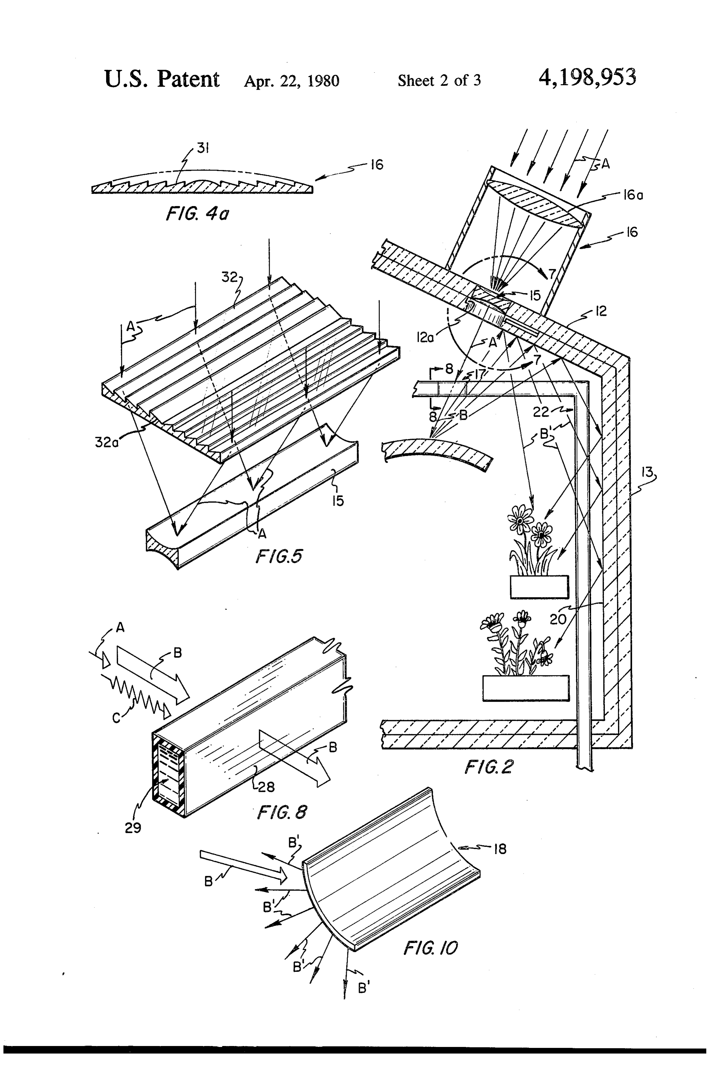
by at least one section or pane of transparent material. rectangular section of sloping lenses sunlight striking The opening cover may or may not involve a focusing thereon shown focused into a narrow band passing into lense configuration and may have a shutter or door a shuttered lense for passage into the energy conserving arranged therewith to cover said opening when the sun greenhouse;
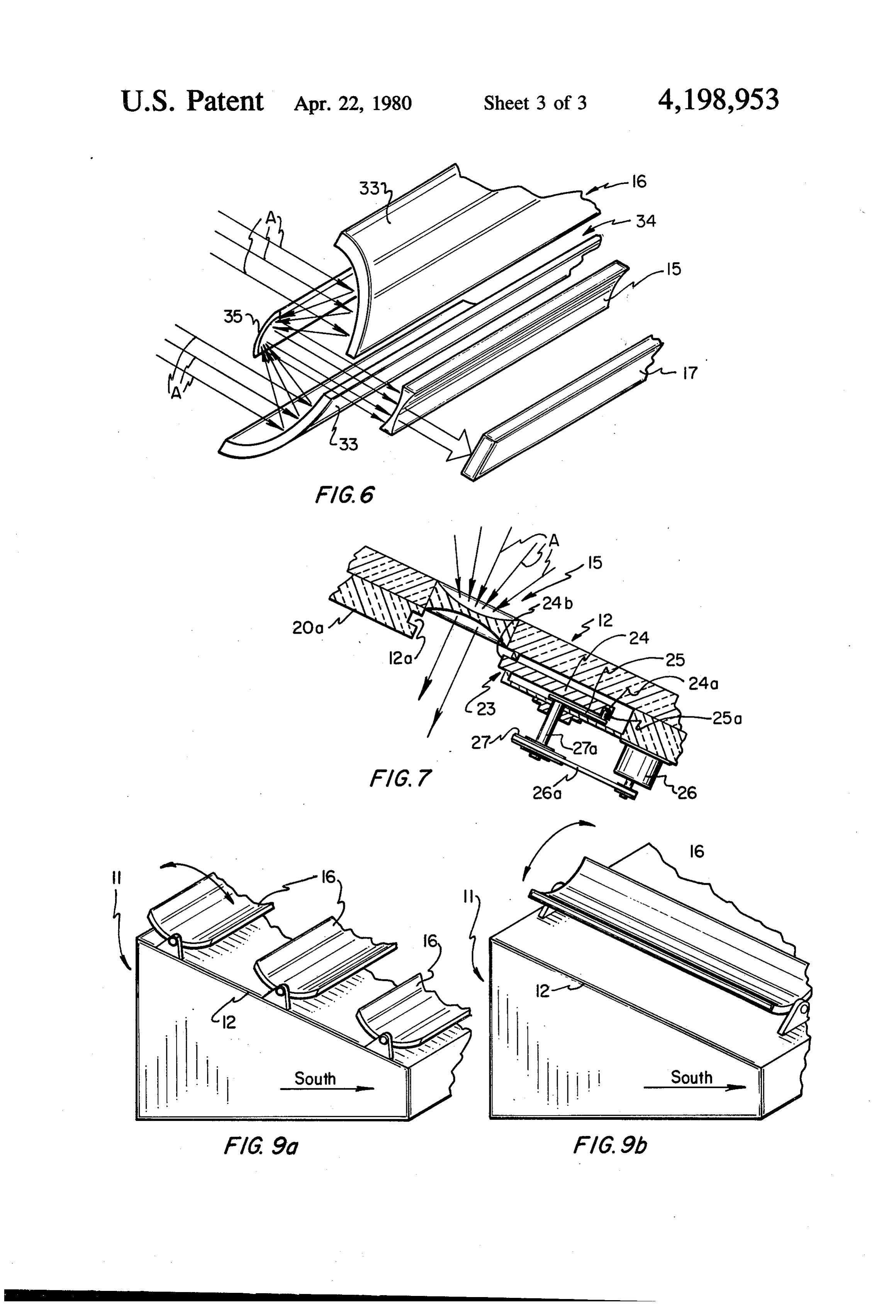
is not shining. Said opening is intended to allow concen- 5 FIG. 6, a third embodiment of a focusing collector trated sunlight to pass therethrough while effecting a shown as consisting of a pair of first concave mirrors minimum compromise of the insulative character of the arranged to receive, focus and reflect sunlight striking structure, restricting to a minimum the loss of heat thereon into a second mirror arranged to reflect that therefrom. Exterior to the structure, and arranged to sunlight therefrom as a narrow band into the shuttered direct focused sunlight into that opening, preferrably, 10 lense;
on the structure roof, is a focusing collector that gathers FIG. 7, a sectional view taken within the lines 7-7 of sunlight striking thereon and focuses it into a beam, FIG. 2, showing a preferred embodiment of a shuttered ribbon, or band for passage through that opening into lense for incorporation with the roof of the energy the structure. The beam, ribbon or band of sunlight, conserving greenhouse;
passed within the structure passes through an infra red 15 FIG. 8, profile sectional view taken within the lines filter trap wherethrough a liquid travels that removes 8-8 of FIG. 2, showing a preferred arrangement of an the infra red or direct heat portion from that sunlight. infra red filter trap collected sunlight shown passing The infra red filter trap may be located as part of the therethrough a liquid traveling therein absorbing the opening cover, or may, and preferrably is, located infra red spectra and passing the other sunlight spectra within the structure proximate to that opening. The 20 therethrough;
sunlight visible spectra portion passes through the trap FIG. 9(a), a number of focusing collectors shown into a rediffuser that spreads the condensed sunlight, arranged to extend across the roof of the energy collect reflecting and directing it over a plant growth area ing greenhouse of FIGS. 1 and 2;
within the structure.
The structure interior walls are preferrably covered 25 theFIG. 9(b), a view like that of FIG. 9(a) only showing roof of the energy conserving greenhouse as having with a reflective coating, as by painting them white or focusing collector arranged longitudinally thereon, having a reflective surface fixed thereto, and the earth which single focusing collector should be taken as being within the structure wherein plants are growing may be one of a number of such focusing collectors, and; likewise covered with a reflective material. So ar ranged, light striking thereon will be reflected there- 30 of FIG. 10, a sectional view taken along the line 10-10 from, that light eventually striking and being absorbed fuser that2,receives
FIG. showing a preferred arrangement of a dif.
the remainder of the sunlight passed by a plant surface.
The present invention by providing a structure that is that light therefrom. trap breaking up and reflecting from the infrared filter well insulated, and minimizing transparent areas in the structure through which direct sunlight is passed, 35 DETALED DESCRIPTION which areas have a lower insulative efficiency than do Referring now to the drawings the structure walls and ceiling, minimizes the areas of
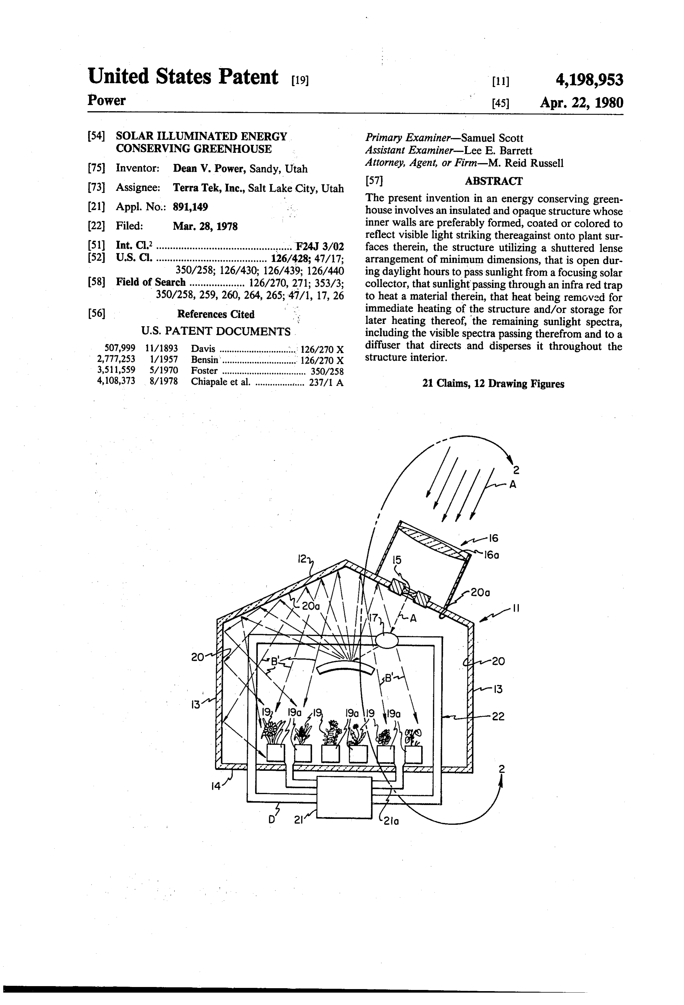
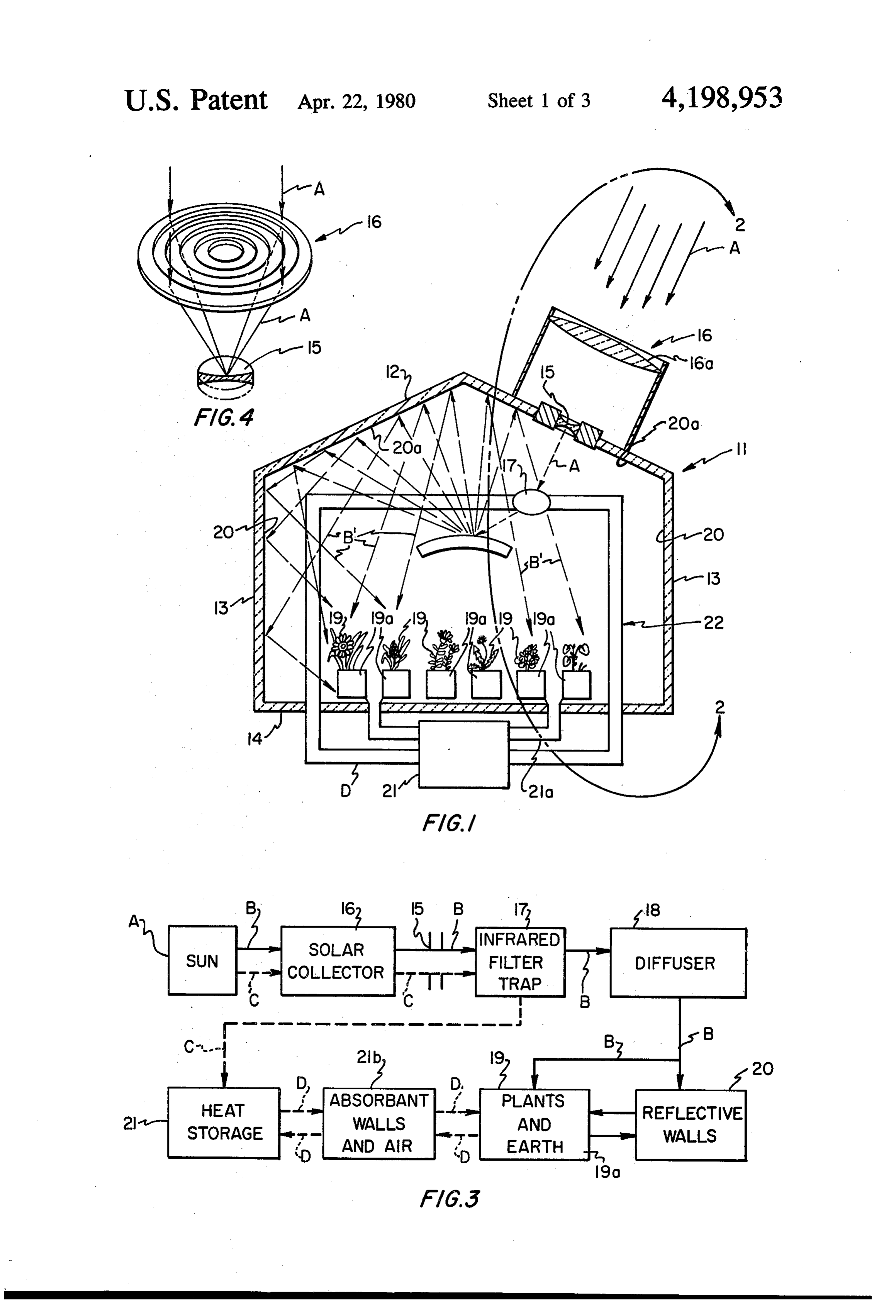
In FIG. 1 the structure that are most susceptible to heat loss. The preferred arrangementis shown a schematic representation of a structure of the present invention therefore provides for of an energy conserving green a structure that will efficiently retain heat and, by utiliz- 40 house 11 of the present invention. The energy conserv ing sunlight for heating as well as for promoting plant ing greenhouse 11, hereinafter referred to as greenhouse growth, provides for a greenhouse that can be operated can, of course, be any desired shape but is shown herein for a minimum energy cost. as preferrably having a gabled roof 12 that is supported Further objects and features of the present invention by upstanding walls 13 that rest on a foundation 14 and will be elaborated on herein and will become apparent 45 should be understood to have at least one entrance into from the following detailed description taken together the interior thereof. The greenhouse 11 preferrably has with the accompanying drawings. at least one sun passing opening formed therethrough THE ORAWINGS that is herein identified as a shuttered lense 15. Shut tered lense 15 is shown arranged through roof 12 to pass
FIG. 1, is a schematic view of a cross section of an 50 sunlight directed thereon from a focusing collector 16. energy conserving greenhouse of the present invention; The focusing collector 16 is arranged, preferrably, on FIG. 2, an enlarged detailed view taken within the the roof 12 to focus and pass sunlight, shown as arrows line 2-2 of FIG. 1, showing a section of the energy A, into the shuttered lense 15, that sunlight, as a beam, conserving greenhouse with arrows A shown repre passes into greenhouse 11 and into an infrared filter trap senting sunlight striking a focusing collector thereon 55 17, hereinafter referred to as I.R. trap 17. Through the that consolidates sunlight and passes it therethrough; I.R. trap 17 a liquid is passed that absorbs the sunlight FIG. 3, a block schematic showing sunlight compo infra red spectra, heating that liquid, passing there ments passing through the elements of the energy con through the sunlight visible spectra, also known as the serving greenhouse of FIGS. 1 and 2; sunlight photosynthetic portion. The I.R. filter trap 17 FIG.4, a profile perspective view of a first preferred 60 is preferrably arranged within the greenhouse 11 and embodiment of a focusing collector for use as shown in should, for obtaining good heat conduction, be located FIGS. 1 and 2, shown as a round lense gathering sun as close to focusing lense 15 as possible and could even light and focusing it into the shuttered lense for passage be arranged as part of the focusing lense 15, but if so into the energy conserving greenhouse; arranged, would tend to pass heat therefrom into the FIG. 4(a), a side elevation view of the focusing col- 65 atmosphere above the structure and so it is preferred to lector of FIG. 4; arrange it within the structure. FIG. 5, a profile perspective view of a second em Shown in FIGS. 1 and 2, a diffuser reflector 18 is bodiment of a focusing collector shown consisting of a included within greenhouse 11 to break up and reflect
Page 7
that visible spectra passed from the I.R. filter trap 17 shuttered lense 15 no matter the sun's attitude. As al onto living plants 19 and earth 19(a) therein. To further ready mentioned herein, sunlight passes from the shut reflect visible spectra light passing from the diffuser 18 tered lense 15, shown also as arrow A, through the infra and visible spectra light reflected off from the leaves of red filter trap 17 and thence against diffuser 18. At the plants 19, the greenhouse 11 interior walls 20 and ceil 5 filter trap the infra red portion of the sunlight is ab ing 200a) are preferrably arranged to reflect light, by sorbed by an infra red absorbing media, preferrably a painting the surfaces white, covered with a mirror sur liquid flowing therein, heating that liquid, the remain face, or the like, to provide for a maximum utilization of der of the sunlight passed therethrough, identified as the photosynthetic fractions in the plant growth pro arrow B, consists of the visible spectra or sunlight pho cess. To further provide a maximum utilization of the 10 tosynthetic fractions and ultra violet. This sunlight re sunlight photosynthetic fractions the greenhouse soil mainder is then deflected and separated by diffuser 19(a) can be covered with a reflective material. So ar reflector 18, shown by arrows Bl, onto and against ranged the only light absorbing surfaces, within the growing plants 19 and earth 19(a) that are shown ar greenhouse 11 would be plants themselves, achieving ranged as a single tier in FIG. 1 and as two tiers in FIG. thereby a maximum utilization of the growth fractions 15 2 and against wall and ceiling inner surfaces 20 and of sunlight visible spectra, and providing a minimization 20(a). As shown in FIG. 2 the greenhouse walls 13 and of the amount of sunlight needed to be passed into the the roof 12 are preferrably well insulated to minimize greenhouse 11 for plant growth. So arranged the sun the heat loss therethrough, and, of course, the shuttered light gathering surface area of the focusing collector 16 lense 15 preferrably involves only a narrow or small and the open area of the shuttered lense 15 can be held 20 area, that should be understood to be only that area to only that required to collect and pass just that mini necessary to pass an amount of sunlight Atherethrough mum sunlight, holding energy losses through that open that is just that light needed for utilization by plants 19 area to the minimum. The above light reflecting ar and earth 19(a) in the growth process.
rangement of providing reflective surfaces to every To further minimize heat loss, as shown in FIG. 2, thing but the growing plants in the greenhouse 11 re 25 through the shuttered lense 15, a shutter cap 23, shown duces to a minimum the ratio of sunlight required as best in FIG. 7, is preferrably included to ciose off and compared to the plant growth area. So arranged, the seal the shuttered lense 15 during hours where sunlight ratio is less than one foot of growth area per each foot is not available. Shutter cap 23, preferrably consists of a of sunlight gathering surface of the focusing collector to plate 24 which can be manual or lever operated but is adequately support growth of plants 19. , 30 preferrably operated by a driver can 25 having a dog The block schematic of FIG. 3 shows the sunlight 25(a) on one end that is journaled into a hole 24(a) in processing flow into and within the greenhouse 11. plate 24. So arranged, by operating motor 26 that turns, Shown therein the entering sunlight is identified as through a belt 26(a), a pulley 27 that rotates a shaft 27(a) arrow A and is shown as consisting of infra red spectra to turn can 25 so as to move plate 24 across the shut portions, broken arrow C, and a visible spectra portion 35 tered lense. So arranged, the end 24(b) of plate 24 will or photosynthetic fractions, including ultra violet, pass into an appropriate notch 12(a) formed in roof 12. shown as solid arrow B. Shown therein the sunlight Obviously, the shutter cap 23, to avoid damage or po spectra is separated at the infra red filter trap 17, that tential fire, if it were inadvertantly left across said shut infrared spectra being utilized for heating a liquid that tered lense when sunlight is passing therethrough, provides, as shown by broken lines C going to a heat should include a failsafe arrangement, not shown, to storage unit 21 and by broken lines D therefrom, heat release said shutter plate 24 so that it will pass back into ing the absorbant walls and air, block 21(b), for immedi its recessed attitude shown in FIG. 7. Also, to further ate heating of the greenhouse 11 interior. A uniform preclude fire or damage, the shutter plate 24 should temperature is thereby achieved for plants 19 and earth have a reflective surface on the surface opposite to the 19(a), the heat storage unit 21 also retaining heat therein 45 focusing collector 16 and should also be formed from a for later greenhouse 11 heating, that heat passing into material that will not be damaged by high temperatures. the greenhouse through duct 21(a), shown in FIG. 1. Sunlight passed from and through shuttered lense 15, The remaining sunlight spectra, specifically the visible as already discussed herein, travels through the I.R. and ultra violet portions passes, from the I.R. filter trap filter trap 17. I.R. filter trap 17, as shown best in FIG. 8, 17, shown as arrow B, against diffuser 18 whereat it is 50 preferrably consists of a transparent or translucent fluid broken up and reflected against plant 19 surfaces, earth carrying pipe 28, shown preferrably herein as a rectan 19(a), reflective walls 20 and ceiling 200), that light gular pipe, that receives the consolidated beam of sun eventually striking and being absorbed by a plant 19 light, arrow A, containing both of infra red spectra, surface, promoting plant growth and providing some arrow C, and visible spectra or photosynthetic fractions heating of the greenhouse 11 interior. 55 and ultra violet, arrow B. As stated, the infrared spec FIG. 2 shows a cross section of a portion of the trathereof, arrow C, is absorbed by fluid 29 traveling in greenhouse 11 showing preferred apparatus for passing pipe 28, the visible spectra or photosynthetic fractions, sunlight therein. It should, however, be obvious that, and ultra violet, arrow B, passing therethrough, for while only one such arrangement is shown a number of diffusion within the greenhouse 11 providing heating such arrangements could be so included as part of 60 and lighting therein. The heated fluid 29 is circulated as greenhouse 11, which additional arrangements would part of a greenhouse heating system 22, shown best in still fall within the scope of this disclosure. Shown in FIG. 1, that consists of the I.R. filter trap 17, a heat FIG. 2, sunlight, arrows A, passes into a sunlight receiv storage section 21 and ducts 21(a). Heat from fluid 29, ing area, shown herein as a lense 16(a) of focusing col not immediately used in greenhouse heating, is trans lector 16. Focusing collector 16 should, of course, be 65 ferred for storage, as into rocks, or the like, not shown. understood to also include a tracking arrangement, not The heating system 22, as needed, may also involve shown, align continuously the lense 16(a) such that fans, pumps or the like, not shown, to transfer heat from captured sunlight will be directed into and through that storage section 21 during the period when the sun
Page 8
is not shining into the air and walls of the greenhouse through, balanced against the greenhouse heat and light 11, to maintain a constant temperature therein. In prac needs. As has been outlined herein, the amount of avail tice, a solution of copper chloride, or an organic salt able photosynthetic fraction of incident sunlight for saturated solution, or the like, has been found to have plant growth can be increased by appropriately includ sufficient infra red spectra heat absorption capabilities ing reflecting surfaces within the greenhouse itself and to absorb that heat portion of the sunlight spectra. even covering the earth wherein the plants grow with a The visible spectra or photosynthetic fractions of reflective surface. As a further consideration in deter sunlight, arrow B, as already stated herein, pass from mining the visible spectra needs within the greenhouse the I.R. filter trap 17 against diffuser 18, shown in FIG. 11 it has been found that the light intensity necessary to 2 and best in FIG. 10. Diffuser 18, preferrably is ar 10 promote plant growth is somewhat dependent upon the ranged to scatter or disperse outwardly the visible spec presence of atmospheric CO2 as well as the interior tra striking thereon but, it should be understood, could temperature of the structure. While the maintenance of be arranged to pass light therethrough, spreading that optimum CO2 level has been difficult in conventional light in such passage, not shown. So arranged, the sun greenhouses due to ventilation requirements, as the light spectra, arrow B, is scattered or broken into multi 15 greenhouse 11 can be closed and is well insulated, the ple beams, shown as arrows B in FIG. 2. To provide CO2 level can therefore be maintained within very close for required light dispersion a faceted reflective surface limits. Further, where it has heretofore been found in is preferrably included with the diffuser 18 and in addi practice that somewhat less than a foot of collector area tion to the convex surface shown in FIGS. 2 and 10, it is needed for each foot of plant growth area, by closely can also involve flat or concave surfaces, not shown, to 20 controlling conditions within the greenhouse and pro direct a portion of the visible spectra striking thereon viding for a full utilization of light passed therein for against another surface, such as a reflective wall or plant growth, as is possible with the present invention, ceiling whereat it is broken up. The respective convex, it is possible for the greenhouse 11 to require as little as concave, or flat surfaces of diffuser 18, shown at 30 in one quarter plant growth area. The greenhouse 11 of F.G. 10, can be covered with such things as dimpled 25 the present invention would preferrably not be designed aluminum, frosted glass, flat white paint, or be a glass at such minimum sunlight admission level but would beaded screen, or the like, for breaking up, and reflect preferrably be arranged to approximately match one ing light striking thereon. Preferrably, however, any square foot or less of collector area for each foot of portion of the diffuser 18 that is intended to redirect greenhouse plant growth area. Further, as the weather light received thereon should be a light reflective sur 30 is unpredictable and certainly changeable, it may be face. necessary in anticipation of a cloudy day to provide for Referring to FIGS. 9(a) and 9(b), the focusing collec artificial illumination within the greenhouse to augment tor 16 could be arranged either laterally or longitudi natural sunlight, which inclusion of artificial illumina nally on the surface of roof 12. In either of configura tion would also come within the scope of the present tion of FIG, 9(a) or 9(b) the present invention should be 35 disclosure.
understood to include an alignment arrangement, not Assuming therefore that the focusing collectors 16 shown, for tracking the sun as it moves from east to have sufficient area to provide the required light within west daily and/or north to south seasonally. greenhouse 11, it is of course desirable that they be Optimumlly, it would be ideal if sufficient energy arranged to focus that sunlight into as small an area or could be removed from sunlight striking the focusing 40 narrow band as possible for projection through shut collectors 16 to both promote the photosynthesis of tered lense 15, the size of which area or band, or course, plants within greenhouse 11, and to satisfy the green determining the size of the shuttered lense. Certain house heating needs. However, as those heating needs focusing collectors have been shown appropriate for are dependent upon outside temperature as well as the use with the greenhouse of the present invention. In amount of sunlight available and the amount actually 45 FIG. 4 is shown an example of a square fresnel lense collected, it is preferrable to include with greenhouse 11 arrangement of a focusing collector, viewed from above a backup heating arrangement, not shown. Certainly, in that is shown to resemble a target, with, in FIG. 4(a) determining heating needs it is necessary to consider: that fresnel lense shown in profile view as consisting of the heat retention qualities of the insulated walls, roof a number of circular incline planes 31 which planes are and flooring of greenhouse 11; the amount of heat gen 50 each themselves prismatic lenses. In this arrangement erated in the plant growth process; the heat available in sunlight striking on each plane is bent, as shown in FIG. the sunlight after its passage through the I.R. filter trap 4, to meet at a common area, at which area shuttered 17; and the heat generated by auxiliary equipment such lense 5 is preferrably arranged. In this configuration as fans, pumps, and the like therein. the shuttered lense 15 could be circular or square in Whether the greenhouse 11 of the present invention 55 shape. A number of such focusing collectors may have provides for either a partial or total energy indepen to be installed with roof 12 to provide for the required dence, it is certainly an improvement in energy conser amount of sunlight, though only one such focusing vation over former conventional greenhouses. There collector is shown herein for purposes of this disclosure. fore, as the cost of construction of such a former green Distinct from the point or small area focusing, shown house as compared to the cost of construction of the with the focusing collector of FIGS. 4 and 4(a), in FIG. greenhouse it of the present invention would be essen 5 is shown a rectangular panel configuration of a focus tially the same, the greenhouse 1a of the present inven ing collector 16, that includes a number of incline plane tion provides a significant energy saving improvement lenses 32 that are shown arranged alongside one an over former greenhouses. other. Each incline plane lense 32 should be taken as Obviously, in calculating sunlight needed in green 65 being a prismatic lense, the lenses facing oppositely on house 11 it is necessary to take into consideration the different sides of a common longitudinal center 32(a), cost of focusing collectors i6 and the size of the shut the incline faces of the two adjacent lenses meeting at tered lense i5 and the predicted heat losses there the longitudinal center 32(a). So arranged, sunlight
Page 9
striking thereon will be focused into a band that passes 4. An energy conserving greenhouse as recited in into a narrow rectangular shuttered lense 15. claim 1, further including,
Another embodiment of a focusing collector 16 is a shutter means arranged for movement across said shown in FIG. 6. Therein, focusing lense 16 is shown as opening to close off and insulate said opening when consisting of two concave mirrors 33 that are arranged 5 sunlight is not directed thereon. as opposite sides of a parabola with a slot or narrow 5. An energy conserving greenhouse as recited in opening 34 therebetween. A collimating mirror 35, is claim 1 wherein the lens means consists of, a type of arranged with its reflective face opposite to opening 34 fresnel lense.
such that sunlight, arrow A, striking on the reflective 6. An energy conserving greenhouse as recited in faces of the concave mirrors 33 will be reflected there 10 claim 1 wherein, the sunlight filter means consists of, from against the collimating mirror 35 that, in turn, an infrared filter arranged to pass a sunlight infrared reflects that sunlight, arrow A, through opening 34 and spectra absorbing media therethrough, through thence through shuttered lense 15 into I.R. filter trap 17. which media the focused sunlight is passed to re In all of the above embodiments of shuttered lense 16 move the infra red spectra therefrom, passing the sunlight is focused into a small area or narrow band for 15 remaining sunlight spectra therethrough. passage through a minimal opening of shuttered lense 7. An energy conserving greenhouse as recited in 15. A wide area of sunlight can thereby be consolidated claim 6, wherein, into a smaller area or narrow band necessitating thereby the infra red filter means is a transparent pipe ar that only a minimum opening be formed through an 20 ranged to pass the infra red spectra absorbing insulated greenhouse roof for passing just sufficient media therethrough.
sunlight therethrough needed to promote plant growth 8. An energy conserving greenhouse as recited in within that greenhouse. The present invention, there claim copper 6, wherein the infra red absorbing media is a chloride solution.
fore, provides for a collection of that amount of sunlight 9. An energy conserving greenhouse as recited in necessary or needed for plant growth for transmittal 25 claim 1, wherein the diffuser means consists of, into a greenhouse such as to require only a minimal a convex surface; and opening formed therethrough so as to compromise to a diffuser surface means covering said convex surface minimum the insulative characteristics of the structure, for breaking into a number of beams and reflecting minimizing thereby heat losses through the structure.
Although a preferred embodiment of my invention in 30 10. An energy conservingthereon.
therefrom light striking an energy conserving greenhouse and the individual claim 1, further including, greenhouse as recited in components thereof have been herein disclosed, it reflective surfaces arranged on the interior walls and should be understood that the present disclosure is ceiling of the structure. made by way of example and that variations are possible without departing from the subject matter coming 35 claim An 11.
energy conserving greenhouse as recited in further including, within the scope of the following claims, which claims a reflective surface arranged over the structure floor I regard as my invention. and over earth areas within said structure wherein I claim: plants grow.
1. A solar illuminated energy conserving greenhouse 12. A solar illuminated energy conserving green comprising, house comprising, a structure adapted for use as a greenhouse having a structure adapted for use as a greenhouse having upstanding walls and a roof thereover and having upstanding walls and a roof thereover and having at least one portal formed therethrough, said walls at least one portal formed therethrough, said walls and roof being insulated appropriately so as to and roof being insulated appropriately so as to minimize heat losses from said structure, said struc 45 minimize heat losses from said structure, said struc ture having also at least one opening formed there ture having also at least one opening formed there through for passing focused sunlight into said through for passing focused sunlight into said structure, said opening being covered appropri structure, said opening being covered appropri ately with a transparent arrangement; ately with a transparent arrangement; a lens means for gathering and focusing sunlight and 50 a solar collector means consisting of at least one re directing said collected sunlight through said open flective surface arranged to focus sunlight received ing into said structure; thereon, and a collimating reflector arranged to a sunlight filtering means for receiving the collected receive, from said reflective surface, said focused sunlight and for removing for use in heating said sunlight to direct appropriately said focused sun structure the infrared spectra portions of that sun 55 light therefrom;
light while passing the remaining spectra portions a sunlight filtering means for receiving the collected of said sunlight therethrough, and; sunlight and for removing for use in heating said diffuser means arranged to receive said remaining structure the infrared spectra portions of that sun spectra portions of said sunlight from said sunlight light while passing the remaining spectra portions filter means spreading and distributing it within of said sunlight therethrough, and; said structure. diffuser means arranged to receive said remaining 2. An energy conserving greenhouse as recited in spectra portions of said sunlight from said sunlight claim 1 wherein the opening for passing sunlight there filter means spreading and distributing it within through has multiple transparent panes arranged there said structure.
OVer, 65 13. An energy conserving greenhouse as recited in 3. An energy conserving greenhouse as recited in claim 12 wherein claim 1, wherein, the opening is closed over by a focus the opening for passing sunlight therethrough has ing lense arrangement. multiple transparent panes arranged thereover.
Page 10
14. An energy conserving greenhouse as recited in theranged infrared filter means is a transparent pipe ar to pass the infra red spectra absorbing claim 12, wherein, media therethrough.
the opening is closed over by a focusing lens arrange- 18. An energy conserving greenhouse as recited in ment. 5 claim 16, wherein, 15. An energy conserving greenhouse as recited in the Eted absorbing media is a copper chloride claim 12, further including, 19. An energy conserving greenhouse as recited in a shutter means arranged for movement across said claim 12, wherein the diffuser means consists of, opening to close off and insulate said opening when 10 Convex surface; and sunlight is not directed thereon. diffuser surface means covering said convex surface for breaking into a number of beams and reflecting 16. An energy conserving greenhouse as recited in therefrom light striking thereon. claim 12, wherein, the sunlight filter means consists of, 20. An energy conserving greenhouse as recited in an infrared filter arranged to pass a sunlight infrared 15 clair further including O as dia therethrough, spectra absorbing media thereth h, throug
ceiling of arranged on the interior walls and the structure.
which media the focused sunlight is passed to re- 21. An energy conserving greenhouse as recited in move the infrared spectra therefrom, passing the claim 20, further including, remaining sunlight spectra therethrough. 20 a reflective surface arranged over the structure floor 8. a and over earth areas within said structure wherein 17. An energy conserving greenhouse as recited in plants grow.
claim 16, wherein, st
Provenance
- Collection
- Cited prior art
- Original PDF
- patentimages.storage.googleapis.com →
- Filed
- 1978-03-28
- Pages
- 10
- Method
- pdftotext (the PDF's own text layer) + pdftoppm 300dpi page scans
- Source
- Google Patents bibliographic record
- Granted
- 1980-04-22
- Inventors
- Dean V. Power; Terra Tek Inc
- Transcribed from
- patentimages.storage.googleapis.com →