patent · US1782732
Cover glass
25 November 1930
Page 1
Drawing sheet — no readable text.
Page 2
Patented Nov. 25, 1930
UNITED STATES PATENT OFFICE
STATES LEELEBBY, OF CORNING, NEW YORK, ASSIGNOR TO CORNING GLAss WORKS, OF CoRNING, NEW YORK, A CORPORATION of NEw York
COVER GLASS
Application filed March 13, 1929. Serial No. 346,755.
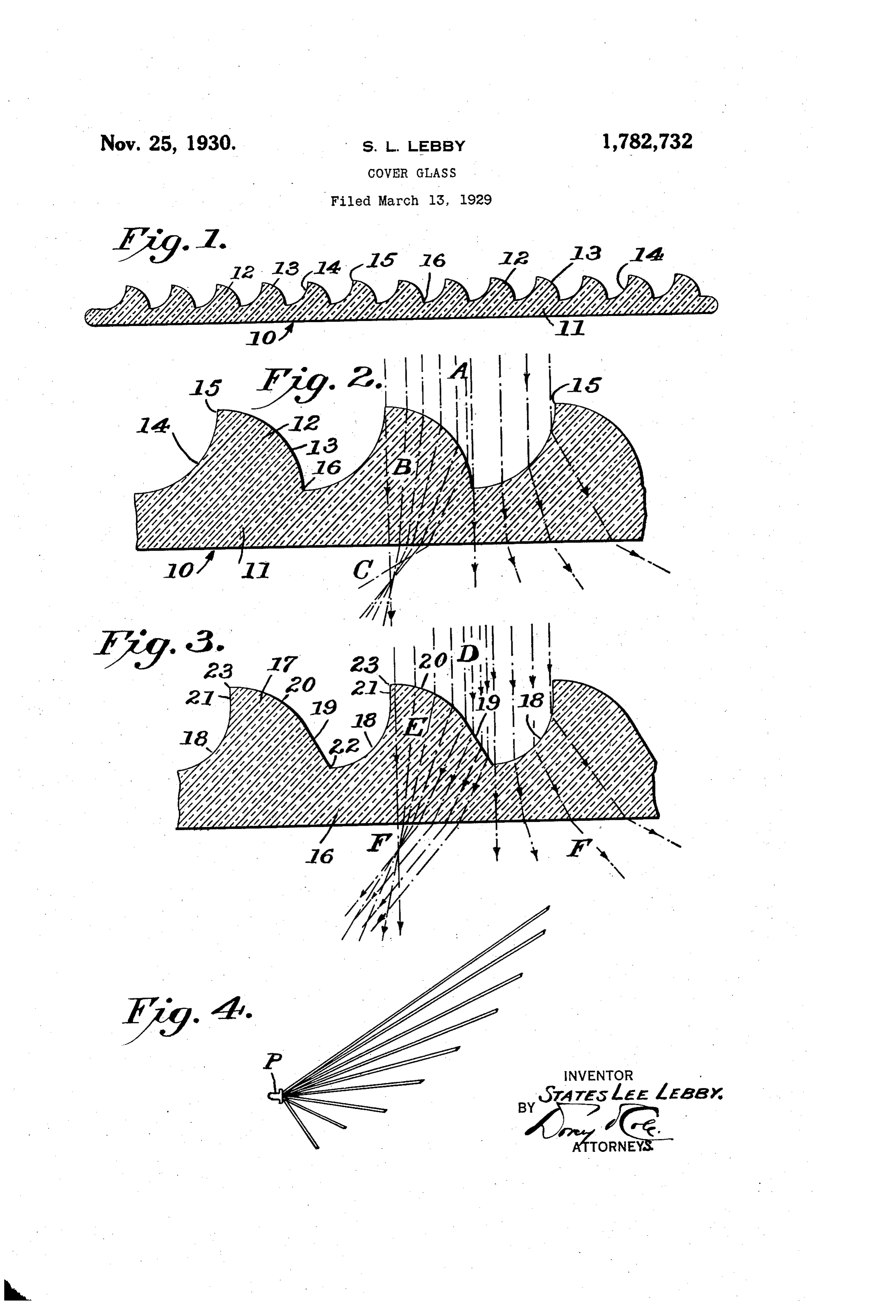
This invention relates to lenses and more Fig. 3 is a view similar to Fig. 2 illustrat particularly to lenses for use in signalling ing in detail a modification of the light re wherein it is desirable to secure a wide spread fracting members; and of the beam of light from a projector. Fig. 4 is a top plan view of a projector 5 In the most common type of spread-light equipped with my improved lens having the lenses, it is customary to provide a plate of modified form of light deflecting members, transparent material such as glass with par and showing diagrammatically the unsym allel flutes which form light refracting mem metrical light distribution produced there bers and cause the light rays issuing from by, the length of the lines representing the 0 the projector to bend outwardly and spread relative light intensity. 60 over a relatively wide area in one plane. The lens 10 is best shown in Figs 1 and 2 Owing to the concave shape of the flutes and comprises a body 11 of transparent ma used, sharp angles are formed between them terial which in the present illustration is which make. the article hard to produce as shown as being flat, though it is to be under it is apt to cause checking. On the other stood that it may be made convex without 65 hand, should an attempt be made to produce departing from the scope of the invention. convex refracting members, the mold equip Formed on the inner side of the lens are light ment must beformed with sharp edges which refracting members 12, each of which is pro are subject to rapid erosion. vided with a convex side 13 and a concave 20 The primary object of the present inven side 14 which joins the outer edge of the tion is to alter the characteristics of a beam convex side 13 at 15 forming an obtuse angle of light from a projector so as to spread it which eliminates sharp edges on the light over an exceedingly wide area in one plane, refracting member. The concave side 14 ex and to facilitate the production of lenses ca tends from the point 15 where it joins the 25 pable of spreading the beam beyond a total convex side 13, of its light refracting mem 75 of sixty (60°) degrees. ber, to a point 16 where it joins the convex A secondary object is to unsymmetrically side of the next adjacent light refracting distribute a projected beam so that its field member 12, there likewise forming an ob of greatest intensity is to one side of the lon tuse angle. It is important that the convex 30 gitudinal axis of the projector and dimin and concave sides of the light refracting 80 - ishes toward the opposite side. - members form an obtuse angle at their junc Among its features the invention embod tion points so that no sharp edges need be ies a lens provided on one face with a series produced either in the ware, or the mold of parallel light deflecting members one side equipment used in its production. In order 35 of each of which is substantially convex to secure full light distribution over the face 85 while the opposite side is substantially con of the lens and prevent the introduction of C.We dark areas thereon, I have found it neces Another feature is the modification of one Sary to end the convex and concave sides 13 or both sides of each light deflecting member and 14 where light passing through their ter 40 to produce the desired distribution of light minals will be normal to them and to the 90 intensity in the spread beam. front face of the lens. In the drawings: : In the modified form of my invention Fig. 1 is a horizontal sectional view shown in Fig. 3, the lens 16 is shown as being through a lens constructed in accordance provided with light refracting members 17 with this invention; each of which is provided with a concave side 05 Fig. 2 is a fragmentary sectional view on 18, and a flat side 19 which extends tangen a greatly enlarged scale showing in detail tially with and merges into a convex surface the light deflecting members and the bending. 20. The inner edge of the flat side 19 joins of the light rays which takes place as they the inner edge of the concave side 18 of the 50 pass through the lens; next adjacent light refracting member 17 at 100
Page 3
an obtuse angle thereby eliminating sharp tor P indicate the relative intensity of the edges, and the curved surface 20 extends from different portions of the beam. While in the foregoing I have set forth the outer edge of the flat side 19 to the outer only two examples of my invention, it is to be edge of the concave side. 18. While the con understood
S struction may be used when the concave side that minor changes in the details 70 18 is of equal or less curvature than the con of construction, combination, and arrange vex surface, it will be seen that when the cur ment of parts may be resorted to, such as ar vature of the concave side is greater than ranging the refracting flat sides at the outer that of the convex side, as shown in Fig. 3, it ends of the concave sides, without departing 20 becomes necessary to interpose a flat surface from the spirit and scope of my invention as 75 21 which extends tangentially from the Outer claimed.
end of the concave side 18 to a point 23 where I claim: .
it joins the outer edge of the convex surface 1. A cover glass comprising a transparent 20, it being understood that since the flat sur plate, and parallel light refracting members 15 face 21 lies parallel with the light rays no re on said plate, each of said light refracting 80 fraction will be produced by this area. members being divided midway of its width To secure a continuous beam throughout into parallel light refracting surfaces of op the entire angle of spread, the interections 22 posite curvature.
of the concave side 18 with the flat side 19, and 2. A cover glass comprising a transparent 85 20 the intersections 23 of the flat surface 21 with plate, and parallel light refracting members the convex surface 20 should be at or slight on said plate, each of said light refracting ly beyond the points where light passing members being divided midway of its width through them will be normal to them and to into parallel light refracting surfaces of op the front face of the lens. By thus preserv posite curvature, the points of intersection of 90 25 ing the relation of the points of intersection 22 the curved surfaces forming obtuse angles. and 23 with the front face of the lens, it be 3. A cover glass comprising a transparent comes apparent that the construction of the plate, and parallel light refracting members refracting members as herein described may On said plate, each of said light refracting be adapted for use with either flat or convex members being divided longitudinally into 30 lenses. light refracting surfaces of opposite curva In using a lens wherein the light refracting ture, and flat surfaces extending tangential members are constructed as illustrated in ly from certain of the curved surfaces to pro Figs. 1 and 2, parallel, light rays A falling duce different intensity of light distribution upon the convex and concave sides 13 and 14 in predetermined regions.
35 of the light refracting members 12 will be 4. A cover glass comprising a transparent 00 directed through the glass as at B and finally plate, and parallel light refracting members emerge as at C with substantially uniform in on said plate, one side of each light refract tensities until the extreme spread angles at ing member being substantially concave, the each side are reached. When the type of lens opposite side of each light refracting member 40 illustrated in Fig. 3 is used, parallel light rays having a convex portion and a flat face ex 05 D, falling on the concave sides 18 and the con tending tangentially therefrom.
STATES LEE LEBBY.
vex curved surfaces 20 of the light refracting members 17, will be directed through the glass as at E and emerge therefrom as at F 45 with substantially uniform intensity until the extreme spread angles of the concave sides 18 are reached. Since the extreme spread an gles of each light refracting member are po
sitioned to direct the light falling thereon to the same side of the lens, it becomes evident that the beam intensity diminishes toward that side. The beam intensity on the opposite side of the lens, however, is increased through the use of the flat sides 19 of the light refract ing members which, while producing a rela tively wide spread of the beam, avoid the ex treme spread angles and hence preserve their light transmitting qualities.
30 In this manner I am enabled to build up a spread beam having its highest intensity on one side of its axis and with diminishing intensities toward the opposite side. Such a beam is illustrated in Fig. 4, wherein the length of the lines radiating from the projec
Provenance
- Collection
- Cited prior art
- Original PDF
- patentimages.storage.googleapis.com →
- Filed
- 1929-03-13
- Pages
- 3
- Method
- pdftotext (the PDF's own text layer) + pdftoppm 300dpi page scans
- Source
- Google Patents bibliographic record
- Granted
- 1930-11-25
- Inventors
- Lebby States Lee; Corning Glass Works
- Transcribed from
- patentimages.storage.googleapis.com →