patent · US4805984
Totally internally reflecting light conduit
21 February 1989
Page 1 — bibliographic record
United States Patent (19) 11 Patent Number: 4,805,984 Cobb, Jr. 45) Date of Patent: Feb. 21, 1989 54 TOTALLY INTERNALLY REFLECTING 3,832,029 8/1974 Bryngdahl ........................ 350/96 T LIGHT CONDUT 3,908,056 9/1975 Anderson ............................ 428/42 3,913,872 10/1975 Weber ........ ... 240/41 R 75 Inventor: Sanford Cobb, Jr., St. Mary's Point, 3,973,828 8/1976 Onoda et al. .. 350/96 WG Minn. 4,120,565 10/1978 Rablet al. ........................... 350/286 73) Assignee: Minnesota Mining and 4,154,219 5/1979 Gupta et al. ...... ... 126/270 Manufacturing Company, St. Paul, 4,235,515 11/1980 Sheiman et al. .. ... 350/138 4,260,220 4/1981 Whitehead .... ... 350/96.28
Minn. 4,297,000 10/1981 Fries ...... ... 350/96.24 21 Appl. No.: 903,657 4,389,085 6/1983 Mori. ..., 350/96.0 4,422,719 12/1983 Orcutt ........ ... 350/96.30 22 Filed: Sep. 5, 1986 4,453,803 6/1984. Hidaka et al. . . 350/96.32 4,466,697 8/1984 Daniel ........... ... 350/96.30
Related U.S. Application Data 4,615,579 10/1986 Whitehead ....................... 350/96.10 63) Continuation-in-part of Ser. No. 799,869, Nov. 21, Primary Examiner-John D. Lee 1985, abandoned, and Ser. No. 819,118, Jan. 15, 1986, Assistant Examiner-Phan Heartney abandoned. Attorney, Agent, or Firm-Donald M. Sell; Stephen W. Buckingham 51l Int. Cl. ................................................ G02B 6/00 52 U.S. Cl. .............................. 350/96.28; 350/96.10; (57) ABSTRACT 350/259; 350/265 A hollow, tubular light conduit including a wall of a 58) Field of Search ............... 350/96.10, 96.24, 96.27, transparent polymeric material, and the wall having a 350/96.28, 96.29, 96.30, 96.34, 259,262, 264, structured surface and an opposite, smooth, glossy sur
face, and at least a portion of the cross-section of the 56 References Cited wall lying in a smooth arcuate curve, wherein light
Re, 28,100 8/1974 Long ..................................... 340/34 range, is contained by total internal reflection. The 247,229 9/1881. Wheeler ... ... 350/96.1 structured surface includes a linear array of substan 729,660 6/1903 Poulson .... as a ph 350/264 tially right angled isosceles prisms arranged side-by-side 1,837,091 12/1931 Adams ..... . 362/301 to form grooves. In addition, the perpendicular sides of 2,022,144 11/1935 Nicolson ................................. 88/25 the prisms make an angle of approximately 45 with the 2,218,227 10/1940 Winnek ................................... 18/61 tangent to the smooth surface. Because of the flexibility 2,232,551 2/1941 Merton .................................... 18/57 of the light conduit and its ability to totally internally 2,279,555 4/1942 Browne et al. ......................... 88/24 3,263,126 7/1966 . 315/241 reflect light, a manipulated light conduit may be utilized 3,312,853 4/1967 Mela .................................... 313/218 in a variety of ways, for example, as a light fixture 3,369,149 2/1968 Grant .................................. 315/168 whereby some of the light directed into the light con 3,386,043 5/1968 Marcatili et al. ... ... 330/4.3 duit is emitted from the light conduit for illumination or 3,417,288 12/1968 Cason, III ........................... 315/241 for use as a secondary light source. A suitable light 3,436,141 4/1969 Comte ................................... 350/96 source may include artificial or solar energy. However, 3,506,331 4/1970 Kompfner ............................. 350/45 when the light fixture operates as a warning light it is 3,511,559 5/1970 Foster ................................. 350/258 3,583,786 6/1971 Marcatili..... ... 350/96 WG preferred that a strobe light be used. 3,641,332 2/1972 Reick et al. ....................... 240/1 EI 3,740,112 6/1973 Lundgren .............. ... 350/96 T 36 Claims, 7 Drawing Sheets
Page 2
Drawing sheet — no readable text.
Page 3
Drawing sheet — no readable text.
Page 4
Drawing sheet — no readable text.
Page 5
Drawing sheet — no readable text.
Page 6
Drawing sheet — no readable text.
Page 7
Drawing sheet — no readable text.
Page 8
Drawing sheet — no readable text.
Page 9
order to efficiently transport light material and labor
TOTALLY INTERNALLY REFLECTING LIGHT costs associated with the assembly or construction of CONDUIT individual planar sections "in octature' to form such a rigid light guide are economic limitations.
CROSS-REFERENCE TO RELATED 5 The art as discussed above does not describe or dis APPLICATIONS close a hollow, tubular light conduit including a wall, of This is a continuation-in-part of application Ser. No. a transparent material, having a structured surface on 799,869, filed Nov. 21, 1985, and application Ser. No. one side and a smooth surface opposite the structured 819,118, filed Jan. 15, 1986, both now abandoned, the surface on the other side lying at least partially, in cross disclosures of which are hereby incorporated by refer 10 section, in a smooth arcuate curve, which will achieve eCe. total internal reflection so that a predetermined portion
FIELD OF THE INVENTION
of the light, incident within an acceptable angular range, is contained by total internal reflection for trans
The present invention relates to a light conduit for 15 porting and/or distributing the light. In addition, it does transporting and/or distributing light and specifically to not describe a light conduit which because of its ability a hollow, tubular light conduit of a transparent material to totally internally reflect incident light within an ac having a structured surface on one side and a smooth ceptable angular range, may be utilized in light fixtures surface opposite the structured surface on the other and lighting systems to transport and to distribute non side, one aspect of which is that the combination of 20 coherent, wideband solar light or artificial light for a surfaces will totally internally reflect light. variety of purposes. Also, the art does not describe a BACKGROUND OF THE INVENTION light conduit which is able to attain a variety of cross sectional shapes with a portion of the wall lying in a
It is known to use optical light pipes or light guides smooth arcuate curve, while maintaining total internal including a semi-solid or solid optical fiber to transport reflection.
light, as illustrated in U.S. Pat. Nos. 4,466,697; 25 4,422,719; and 3,641,332. Some such devices have in SUMMARY OF THE INVENTION cluded reflective sleeves surrounding the light transmit The present invention provides a totally internally ting fiber. For example, the inner surface of the sleeve reflecting light conduit for transporting and/or distrib could be formed with a reflective layer or a layer of uting the light including a wall, of a transparent mate material having a relatively low refractive index com 30 rial, having a structured surface on one side and a pared to that of the core, such as air, interposed be tween the sleeve and the core. However, a particular smooth other surface opposite the structured surface on the side, and at least a portion of the cross-section of problem is that such devices do not easily lend them the wall lying in a smooth arcuate curve. The struc selves to transporting sufficient light for illumination tured surface consists of a linear array of substantially
because of the size necessary. In addition, utilization of right angled isosceles prisms such devices would be bulky and require a substantial perpendicular sides of each arranged prism side by side. The make an angle of amount of material, which would increase their weight approximately 45 with the tangent to the adjacent and cost.
In addition, optical wave guides have been utilized to smooth surface opposite the structured surface. Even guide electro-magnetic wave energy, as illustrated in though a portion of the wall lies in a smooth arcuate U.S. Pat. Nos. 4,453,803; 3,973,828; 3,583,786; curve, light entering the light conduit within an accept 3,506,331; 3,436,141; and 3,386,043. Such devices in able angular range is contained by total internal reflec clude a sleeve portion or a hollow optical fiber. Similar tion as it travels along the length of the light conduit. to the optical light pipes or light guides described Further, under certain conditions, the efficiency of the above, such devices have had a problem associated with 45 itlight transportability of the light conduit is enhanced as approaches a circular or an elliptical cross-section.
the assembly and cost of the devices. Also, such devices are designed primarily to carry information for commu The ability to maintain reflectivity while only requir nication purposes in a single electromagnetic mode to ing that a portion of the wall lie in an arcuate curve, increase the bandwidth of the information. This re results in the light conduit being able to attain a variety quires a highly specialized light source and optical sys 50 of cross-sectional shapes or configurations, such as, for tem to properly direct quasi-monochromatic light into example, circular or elliptical. This eliminates optical the device for propagation. constraints regarding construction and orientation of Further, a light guide made of a transparent material the wall, and substantially reduces cost and increases having substantially planar inner and outer surfaces the total amount of light acceptable for transportation which are "in octature" has been utilized to transport 55 and/or distribution. Also, the linear array of right an light, as illustrated in U.S. Pat. No. 4,260,220. This gled isosceles prisms may be disposed parallel or at device is the most pertinent to the present invention. almost any angle to the axis of the conduit. However, The device includes rigid polymeric sheets of a trans light will only be totally internally reflected and trans parent material having a structured surface on one side ported along the length of the light conduit if it is prop and a smooth surface opposite the structured surface on erly directed into the light conduit. the other side whereby light entering the light guide at Advantages of the light conduit of the present inven an angle less than a predetermined maximum is totally tion are the ability to attain a variety of cross-sectional internally reflected. However, a significant problem or shapes, and that it can be used in light fixtures and light limitation has been encountered with the use of such ing systems to transport and distribute light when the devices, namely the fact that it is restricted or con 65 light conduit is manipulated to allow some of the light strained to a relatively small angular range of accept to pass through the wall of the light conduit without able light rays. In addition, optical constraints require being totally internally reflected. Thus, the light con that the flatness of the sides be rigidly maintained in duit can be easily integrated into present light fixtures
Page 10
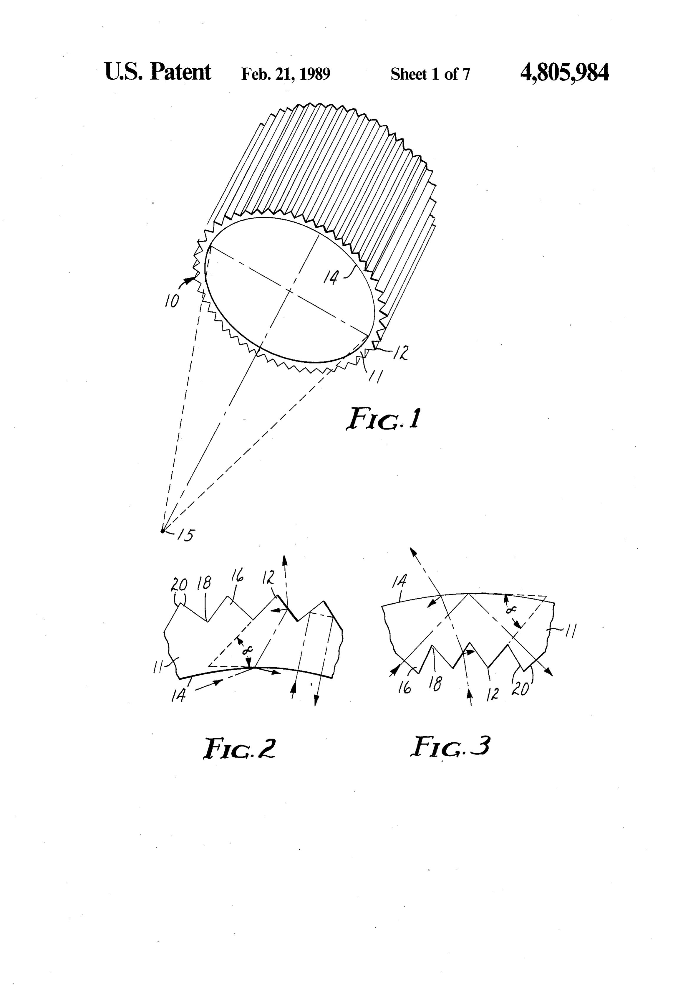
without the need for specialized equipment or substan illustrated in FIGS. 2 and 3. The light will be totally tial redesign of the fixture. internally reflected when the light refracted by the first A fixture according to the present invention com surface strikes the second surface at an angle, with re prises a housing, generally opaque, surrounding a light spect to the normal, greater than the critical angle. This conduit, and at least one side of the housing includes an critical angle is defined as the arcsine of the ratio of the optical window through which light is emitted and index of refraction of the surrounding medium (typi distributed from the housing for illumination or for use cally air) to that of the wall material. In addition, a as a secondary light source. A diffuser may be placed in significant portion of the incident light striking either of the optical window to redistribute or disperse the light the surfaces 12 or 14, outside the acceptable angular in a desired fashion, such as, for example, to scatter, 10 range, will be transmitted and the remainder will be soften or spread the light more evenly. The light source reflected, as illustrated in FIGS. 2 and 3. In either situa may include solar energy and/or artificial light. tion, there is negligible absorption of light by the wall DESCRIPTION OF THE DRAWINGS material.
The structured surface 12 includes a linear array of
The present invention will be more fully described 15 substantially right angled isosceles prisms 16 arranged with reference to the accompanying drawings wherein side-by-side in parallel relationship to form a plurality of like reference numerals identify corresponding compo grooves 18 running the length of the light conduit 10, as nents, and:
FIG. 1 is a perspective view of a light conduit of the illustrated in FIGS. 2 and 3. The perpendicular sides 20 are nominally flat and make an angle alpha (a), of ap
FIG. 2 is a fragmentary end view of the light conduit proximately smooth surface 45, with the tangent to the adjacent 14. The exactness of the prisms and their of FIG. 1; orientation is essential for light transportation, but is not FIG. 3 is a fragmentary end view similar to FIG. 2 as essential for illumination or for use as a secondary depicting the light conduit when the smooth surface is light source.
The particular material used for the wall 11 of the
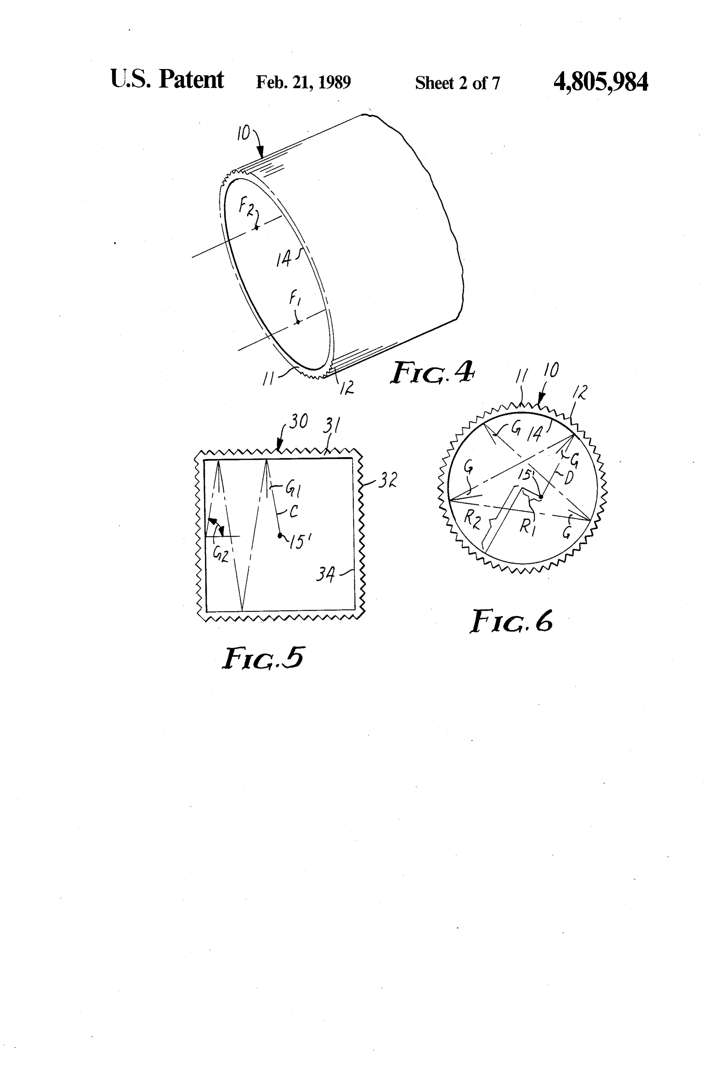
FIG. 4 is a perspective view of the light conduit light conduit 10 may vary, but it is intended that in most having an elliptical cross-section; applications the material be generally flexible. It is, FIG. 5 is an end view of a prior art light guide show ing the front surface reflection of light rays; however, essential that the material be transparent, and preferably homogeneous and isotropic, such as for ex
FIG. 6 is an end view of the light conduit of FIG. 1 30 ample illustrating the front surface reflection of light rays; polymeric materials or glass. Useful polymeric FIG. 7 is a perspective view of the light conduit grades of,forforthisexample, materials purpose are commercially available acrylics and polycarbonates illustrating light ray geometry;
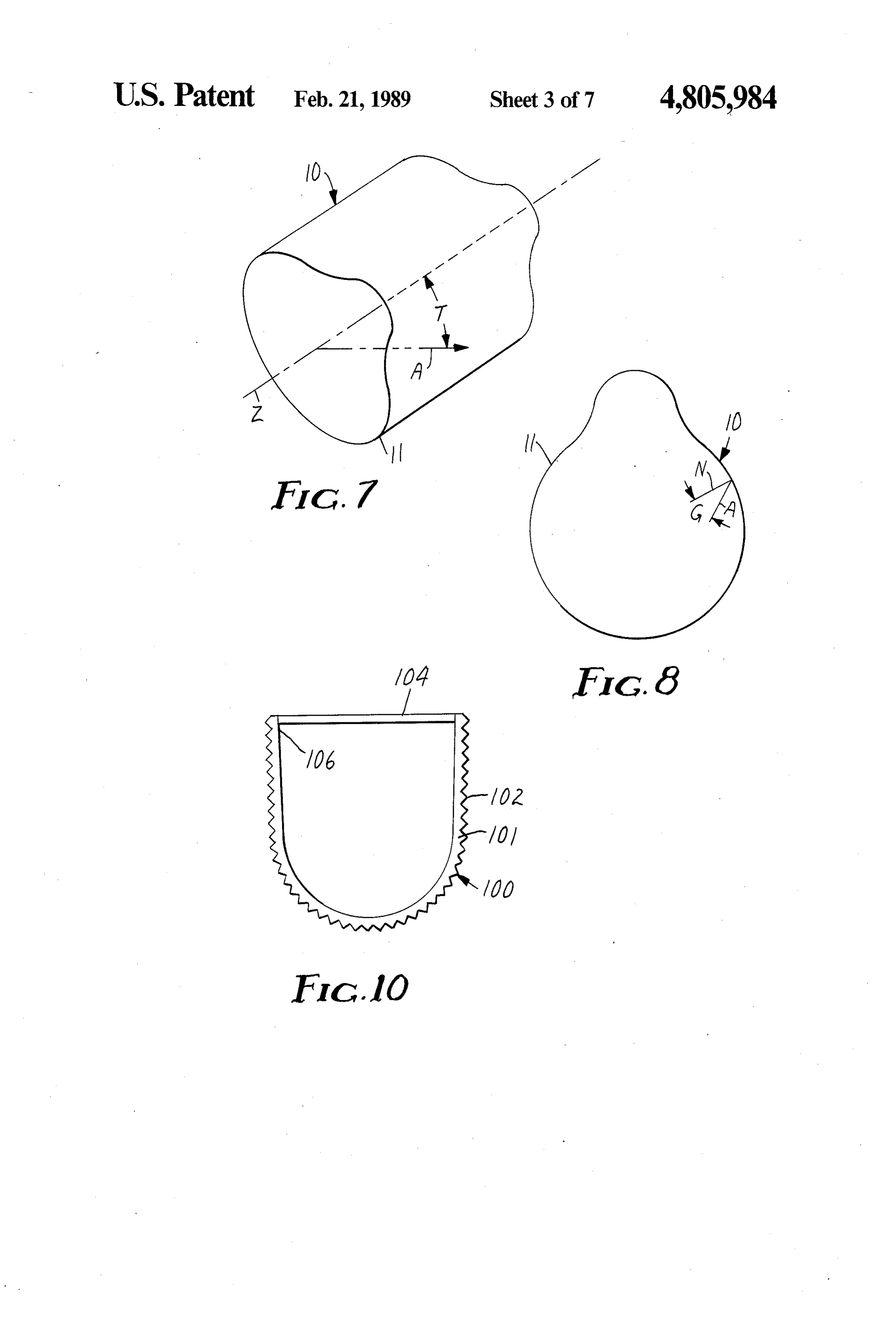
FIG. 8 is an end view of the light conduit illustrated having nominal indices of refraction of 1.49 and 1.58, in FIG. 7; 35 respectively. Other useful polymers are polypropyl FIG. 9 is a graph illustrating the mathematical rela enes, polyurethanes, polystyrenes, polyvinyl chlorides, tionship between the angles of light rays; and the like. The particular material selected is not FIG. 10 is an end view of the light conduit including significant to the invention hereof, so long as it provides a reflective surface; the described function. Normally, the manufacturers of FIG. 11 is a perspective view of a light fixture utiliz this product will select the best commercially available ing the light conduit of the present invention; material based upon price, application and manufactur FIG. 12 is a perspective view of an alternative em ing process. However, acrylics and polycarbonates are bodiment of the light fixture; of particular interest because of their high indices of FIG. 13 is a perspective view of a second alternative refraction and physical properties, i.e. weatherability, embodiment of the light fixture; 45 ultraviolet resistance, dimensional stability, and temper FIG. 14 is a perspective view of a further embodi ature tolerance to name a few.
ment of the light fixture; There are several ways to mass produce the wall 11 FIG. 15 is a schematic, perspective view of two light of the light conduit 10 of the present invention which conduits of the present invention showing a telescoping are well known to those skilled in the art, for example as feature for interconnecting the light conduits; and 50 illustrated in U.S. Pat. Nos. 3,689,346, 4,244,683, FIG. 16 is a schematic, perspective view showing 4,576,850 and U.K. patent application No. GB two light conduits of the present invention and a sleeve 2,127,344A, the disclosures of which are hereby incor for interconnecting the light conduits. porated by reference. The particular manufacturing DETAILED DESCRIPTION OF A PREFERRED process is not essential to the present invention, and is a 55 matter of choice based upon economics and availability.
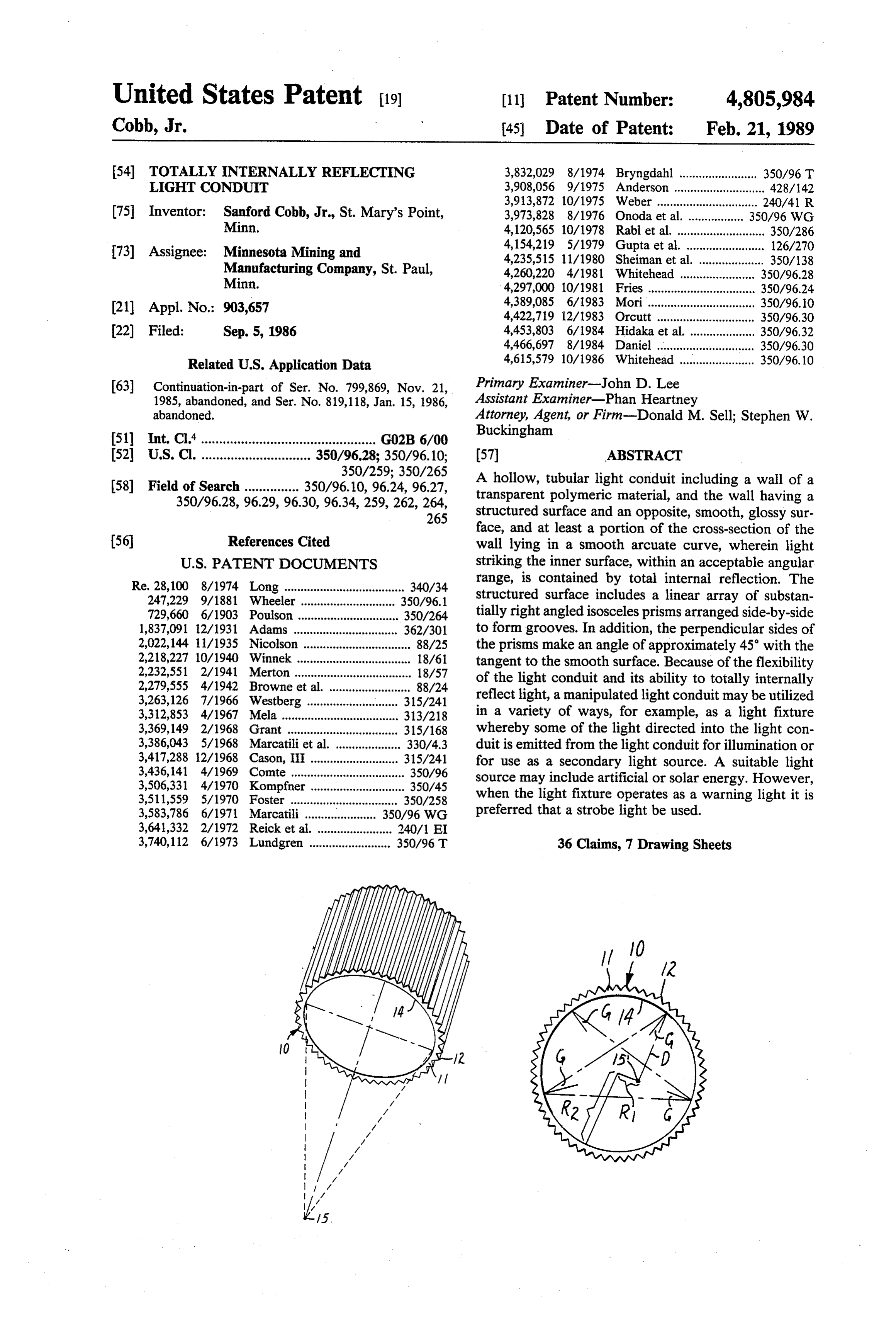
EMBODIMENT However, it is preferred that a thin, flexible film be Referring to FIG. 1 of the drawings, a hollow, tubu utilized as disclosed in U.S. patent application Ser. No. lar light conduit of the present invention, generally 799,869 (abandoned) inventor Sanford Cobb, Jr. and designated 10, may be used to transport and/or distrib filed concurrently herewith), the disclosure of which is ute a predetermined portion of light within the conduit. hereby incorporated by reference. Such a film may be The light conduit includes a wall 11, of a transparent curled into a tubular configuration and the seam fas material, having a structured surface 12 on one side and tened by welding, or for particular applications, it may a smooth surface 14 opposite the structured surface on be acceptable to simply overlap or join the edges. In the other side, and at least a portion of the cross-section addition, it should be appreciated that the light conduit of the wall lying in a smooth arcuate curve. Incident 65 10 may be extruded or molded to provide a flexible or light from a light source 15 striking either of the sur rigid unitary member. The description of the present faces 12 or 14, within an acceptable angular range, will light conduit 10 and its use will proceed on the basis of be totally internally reflected at the other surface, as its being formed by curling a thin, flexible film.
Page 11
The thickness of the wall of the light conduit is not initially strikes the smooth surface 34 of wall 31 at angle particularly essential to the present invention. How G1, but after several first surface reflections strikes the ever, the applicability of the light conduit 10 is depen adjacent smooth surface 34 at angle G2 equal to dent upon the thickness of the wall to the extent that the (90-G1) degrees. Thus, G2 may approach 90 degrees, curled film or unitary conduit may be formed into a as G1 approaches zero.
variety of tubular cross-sectional shapes, such as circu In the circular light conduit 10 of the present inven lar or elliptical, as illustrated in FIGS. 1 and 4. For tion, illustrated in FIG. 6, however, no increase in angle example, an acrylic film having a nominal thickness of G can occur because of the geometrical symmetry of 0.015 of an inch and having about 70 prisms per inch the light conduit. Thus, the circular light conduit 10 has exhibits sufficient flexibility to be capable of being 10 an acceptable angular range of 90 degrees for a light curled into a cylindrical light conduit 10 having a mini source mum diameter of approximately 3 inches. In addition, light raypoint at the center of curvature, i.e. R1 =0. A D which strikes the smooth surface 14 initially such a film will be rigid and self-supporting enough to at some angle easily maintain its shape when curled into a cylindrical 14 at that sameG angle will always strike the smooth surface G and the angle will never in light conduit 10 having a diameter of approximately 18 15 crease or decrease, as illustrated in FIG. 6, for the case inches. This ability to maintain reflectivity results in the light conduit 10 being able to be utilized in a variety of of a light source point 15' not centered in the circular ways, and eliminates the prior requirement that the light conduit 10.
optically functional surfaces be rigidly maintained "in Light that is not reflected at the smooth surface 14 octature'. 20 passes through a curved interface, undergoes total inter It has been found that certain cross-sectional shapes, nal reflection at the prism surfaces 20, and returns to the especially circular and elliptical, provide enhanced opti hollow inside of the light conduit 10 through the same cal performance by increasing the acceptable angular curved surface. The net effect of this double passage range of transportable light rays. A prior art light guide through curved surface is to diverge the light beam as if 30, see FIG. 5, with planar walls 31 and of rectangular 25 it has passed through a negative lens. Because of the cross-section with the structured surface 32 on the outer small prism 16 size in relation to the radius of curvature side, is restricted with respect to the angular range of R, the paraxial lens approximation can be applied, the rays which can be transported. In contrast, light con thin lens approximation can be used because the wall 11 duits 10 of the present invention, having at least a por- . is thin in relation to the radius of curvature. tion of the wall 11 lying in a smooth arcuate curve, 30 The maximum divergence (change in angle G) can accept a greater angular range of light rays. Specifi therefore be determined as follows:
cally, as illustrated in FIG. 6, a circular cross-sectional light conduit 10, with the prisms 16 on the outer, con vex side, has been found to provide optimum perfor mance. However, it should be appreciated that a variety 35 where of cross-sectional shapes may be utilized depending G1 and G2 are the projected ray angles G with re upon the requirements of the application, and that the spect to the symmetry axis (the radial bisector) structured surface 12 may be on the inner side, as long before and after refraction, respectively; as at least a portion of the wall 11 lies in a smooth arcu y is the ray height (distance from the rays point of ate curve. The following analysis will proceed on the incidence to the symmetry axis); and basis of the light conduit illustrated in FIG. 6. F is the focal length of the lens. F=2(n'-1)/R, To demonstrate this point clearly, it is necessary to where R is the radius of curvature and n' is the define angles T and G, as illustrated in FIGS. 7 and 8. effective index of refraction defined above. As illustrated in FIG. 7, angle T is the angle between a Therefore, the change (G2-G1) in angle may be given light ray A and the axis Z of the light conduit 10, 45 positive or negative and will have magnitude y/F. Plug which is assumed in this case to be parallel to the direc ging in approximate values for y and F and assuming a tion of the prisms. Angle G is the angle, when viewed in moderate value (20 degrees) for angle T, we find that cross-section, between the given light ray A and the the maximum value of (G2-G1) is in the vicinity of 1.3 normal N to the wall 11 of the light conduit 10, as illus degrees.
trated in FIG. 8. It can be determined that for a given reflected Inbyconclusion,
total the angle G for the ray which is internal reflection (TIR) may increase angle T there is a maximum acceptable angle of G, i.e.
Gmax, for light transport, beyond which light may es or decrease by up to 1.3 degrees, while the average ray cape the light conduit 10. Conversely, for a given angle will be deviated much less. The net effect of this refrac G there is a maximum acceptable angle of T, i.e. Tina, tive power is to gradually fan the rays out in the trans for the incident light ray A. However, when angle T is 55 verse direction.
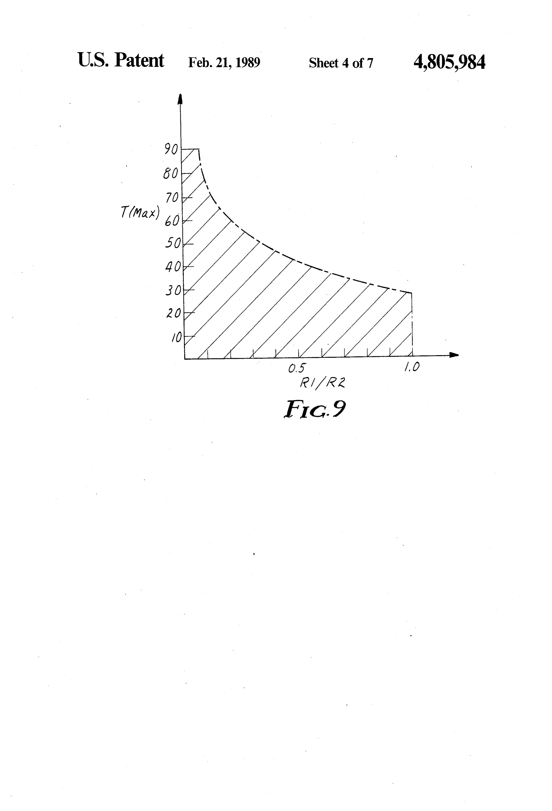
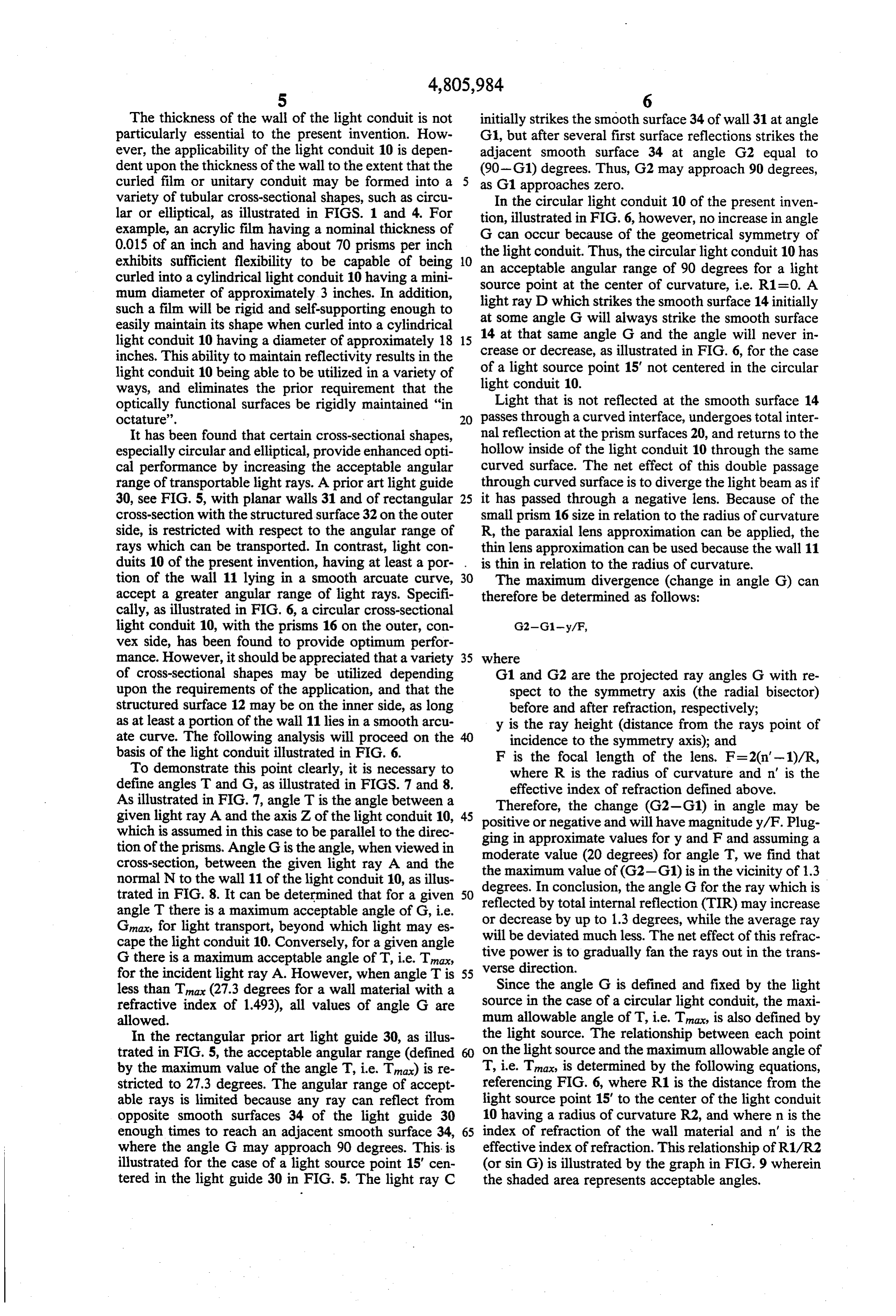
less than Tina (27.3 degrees for a wall material with a Since the angle G is defined and fixed by the light refractive index of 1493), all values of angle G are source in the case of a circular light conduit, the maxi allowed. mum allowable angle of T, i.e. Tina, is also defined by In the rectangular prior art light guide 30, as illus the light source. The relationship between each point trated in FIG. 5, the acceptable angular range (defined on the light source and the maximum allowable angle of by the maximum value of the angle T, i.e. Tna) is re T, i.e. Tmax, is determined by the following equations, stricted to 27.3 degrees. The angular range of accept referencing FIG. 6, where R1 is the distance from the able rays is limited because any ray can reflect from light source point 15' to the center of the light conduit opposite smooth surfaces 34 of the light guide 30 10 having a radius of curvature R2, and where n is the enough times to reach an adjacent smooth surface 34, 65 index of refraction of the wall material and n' is the where the angle G may approach 90 degrees. This is effective index of refraction. This relationship of R1/R2 illustrated for the case of a light source point 15' cen (or sin G) is illustrated by the graph in FIG. 9 wherein tered in the light guide 30 in FIG. 5. The light ray C the shaded area represents acceptable angles.
Page 12
imperfections, such as non-optically smooth prism sur faces and/or non-optically sharp corners, or structuring
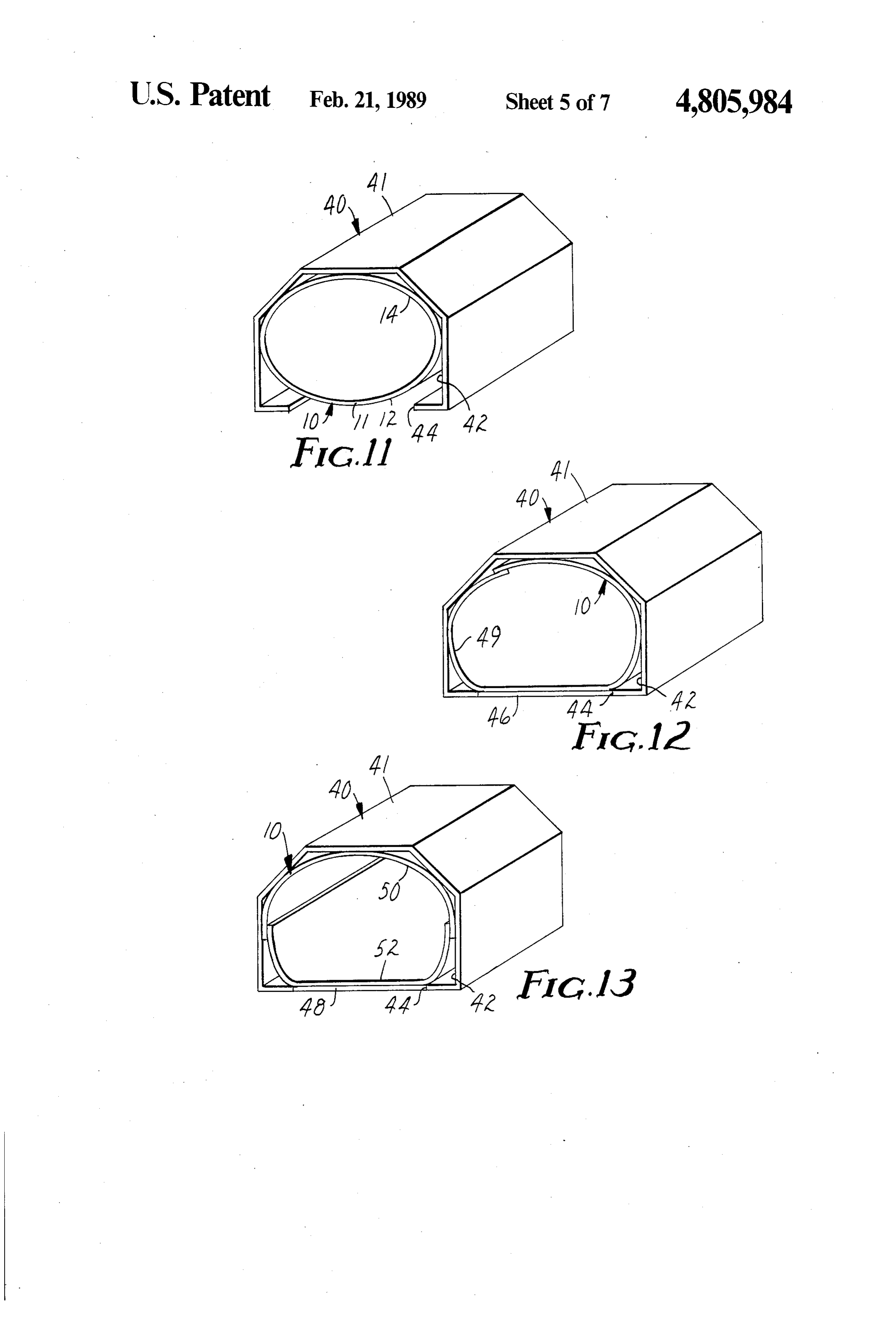
the smooth surface 14. Thus, the light conduit 10 may be used as a light fixture or in a light fixture 40 as an
Find Tmax from n' and Gnax where illuminator or a secondary light source, as illustrated in FIG. 11 wherein a manipulated light conduit 10 is placed in a housing 41 having an inner surface 42. The
Gmax = sin-(n sin s' - sin (+)) housing may be made by forming, bending or extruding a suitable material, such as aluminum, and for increased 10 efficiency a specular or diffuse reflective coating may and be provided to the inner surface 42. The surface 42 may include a plurality of reflective elements (not shown) cos’(Tina) which direct light striking the elements in a desired - - 15 direction for transporting or illuminating purposes.
1 - cos’(Tina) Thus, light may be directed into the light fixture and emitted through at least one optical window 44, such as,
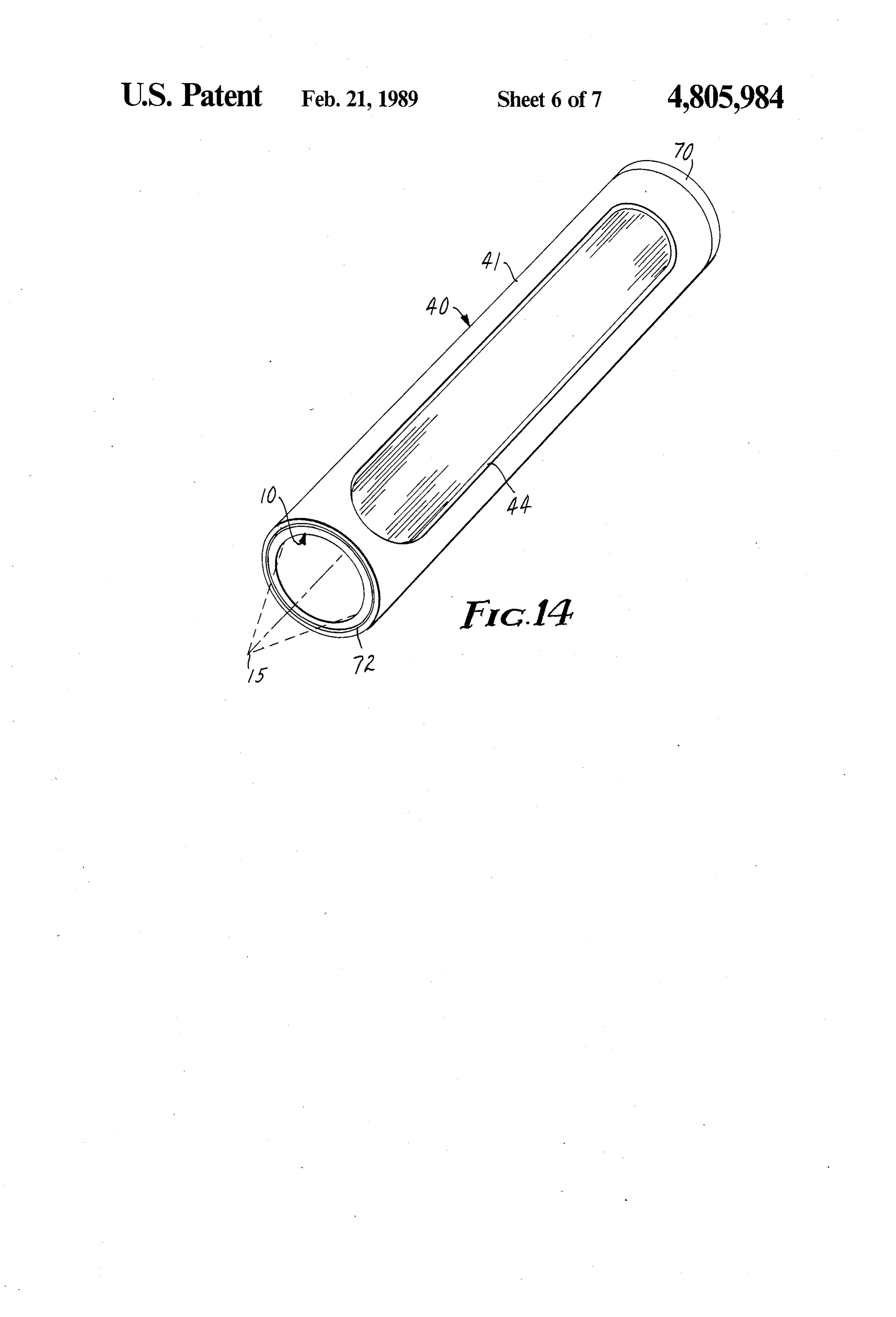
When R1 = R2 (i.e. the light source point 15" lies on the for example, an opening in the housing, for illumination smooth surface 14 of the light conduit 10) Gnax is 90 or for use as a secondary light source, as illustrated in degrees, and the same Tmax (27.3 degrees when 20 FIGS. 12, 13, and 14. In addition, a diffuser 46 may be n = 1.493) as the rectangular light guide 30 is obtained. provided in the window 44 to redistribute or disperse But when the light source point 15' is inside the light the light in a desired fashion, as illustrated in FIG. 12. conduit 10, as is much more commonly the case, the Also, a sign 48 or the like may be provided in the win maximum allowable angle of T, i.e. Tmax, increases dow 44 for advertising, displaying, signaling or warning significantly, as shown in the graph of FIG. 9, which 25 purposes, as illustrated in FIG. 13. illustrates the relationship between the ratio R1/R2 (or When the light fixture operates as a warning light, as sin G) and the maxium allowable value of the angle T, illustrated in FIG. 14, for emergency vehicles, barri i.e. Tina. This means that more of the light from the cades and the like, it is preferred that a light source light source can be transported without loss, and makes the light conduit design simpler and more efficient. 30 which produces high-intensity short-duration light pulses, such as a strobe light by electric discharge in a
In addition, as illustrated in FIG. 10, a light conduit gas, be associated at one end of the light conduit 10. It 100 can be formed by curling the film or molding the unitary conduit into a wall 101 having at least one open should also be appreciated that an incandescent light or side 106. A reflective surface 104, such as a mirror, may other light source can be used. In addition, reflector 70 be associated with the opening 106 so that light directed 35 should be associated with the other end so that the light into the light conduit 100 and incident upon the reflec reflects back up the light conduit 10 to aid in the even tive surface 104 is redirected within the light conduit distribution of the light through the optical window 44. 100. Further, it has been found that it is possible to eliminate hot spots near certain light sources by covering a por
Application and Use tion of the light conduit 10 adjacent the light source Several of the various applications and uses of the 40 with an opaque reflector 72.
light conduit 10 of the present invention will now be The light conduit 10, for ease of assembly or replace described. The most promising and revolutionary use of ment in the light fixture 40, may be formed by overlap the light conduit 10 is due to its ability to be formed into ping the edges of the thin, flexible film 49, as illustrated a variety of cross-sectional shapes while maintaining in FIG. 12 or by overlapping two pieces of film 50 and total internal reflection so that light properly directed 45 52 as illustrated in FIG. 13, wherein the housing 41 into the light conduit 10 is transported and/or distrib cooperates with the forces exerted by the curling of the uted as it travels along the length of the light conduit. film into a hollow, tubular light conduit 10 while main The light conduit 10 may be formed with the structured taining an advantageous degree of acceptable angles. surface 12 on the inner concave side or on the outer convex side. For example, when optimum light trans 50 This allows for long light fixtures and light conduits, relative to the cross-section, to be used.
port is required, the light conduit 10 may be formed A suitable light source 15 may include an artificial having a circular cross-section with the prisms on the source, as disclosed, for example, in U.S. Pat. No. Re. outer convex side and parallel to the axis of the light conduit and the smooth surface 14 being glossy. Also, it 28,100; U.S. Pat. Nos. 3,417,288; 3,369,149; 3,312,853; should be appreciated that the light conduit may be 55 3,263,126; 3,127,113; 1,837,091 and 247,229, the disclo sures of which are hereby incorporated by reference, or similarly formed with an elliptical cross-section when the utilization of solar energy, as disclosed, for example, utilizing a small light source located at one of the foci
For F2, as illustrated in FIG. 4. In addition, for partic in U.S. Pat. Nos. 4,389,085; 4,297,000; 3,511,559; ular applications, the linear array of prisms 16 may be 2,022,144; and 729,660, the disclosures of which are disposed at almost any angle to the axis of the conduit 60 hereby incorporated by reference.
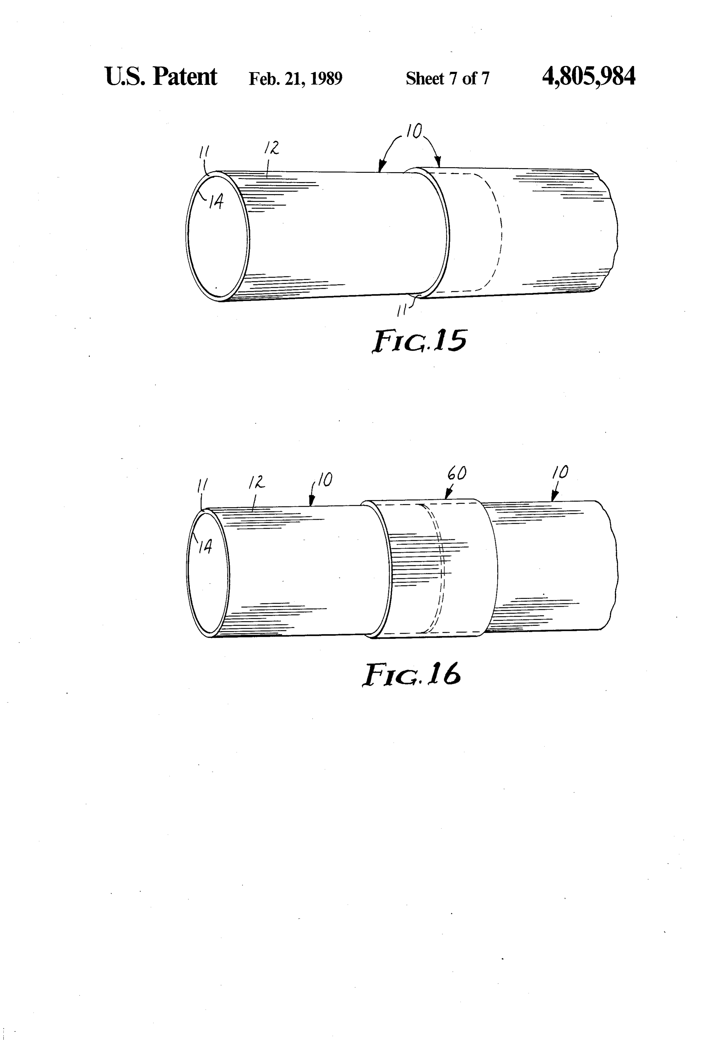
when light from the light source 15 is properly directed. To provide for ease of interconnection, as illustrated Further, under certain circumstances, the prisms may in FIG. 15, a length of conduit 10 may be telescopically be disposed orthogonally when the prisms are on the tapered or alternatively diametered so that one length inner concave side. may be inserted into another to transport and/or illumi The performance of the light conduit 10 may be ma 65 nate as part of a lighting system or any other purpose. nipulated so that it may be used to transport and distrib As an alternative, sections of the light conduit 10 may ute light by, either singularly or in combination, adding be abutted and a sleeve 60 of the same material placed diffusing or reflecting particles, or by incorporating over the abutting ends, as illustrated in FIG. 16.
Page 13
While a preferred embodiment of the present inven to said smooth surface opposite said structured tion and several alternative embodiments have been surface;
described so as to enable one skilled in the art to prac performance manipulating means associated with said tice the techniques of the present invention, the preced wall member for allowing light to be emitted from ing description is intended to be exemplary and should said light conduit through said wall member with not be used to limit the scope of the invention. The out being contained within said light fixture by scope of the invention should be determined only by total internal reflection; reference to the following claims. optical window means in said housing for allowing I claim: the emission of light from said light conduit 1. A hollow, tubular light conduit for transporting 10 through said optical window means; and light there along and/or distributing light therefrom, light source means associated with said light conduit comprising a wall member of a transparent material, for supplying light into said light conduit so that said wall member including a structured surface on one light entering said light conduit may be emitted side and a smooth surface opposite said structured sur from said light conduit and may thereby exit from face on the other side, at least a portion of the cross-sec 15 said light fixture through said optical window tion of said wall member lying in a smooth arcuate aS curve, said structured surface having a linear array of substantially right angled isosceles prisms arranged transparentlight 11. The fixture defined in claim 10 wherein said material is a polymeric material.
side-by-side, the perpendicular sides of said prisms mak 12. The light fixture defined in claim 10 wherein said ing an angle of approximately 45 with the tangent to 20 hollow, tubular light conduit is substantially circular in said smooth surface opposite said structured surface, so cross-section.
that a predetermined portion of the light entering the 13. The light fixture defined in claim 10 further com light conduit within an acceptable angular range, is prising diffuser means associated with said optical win contained by total internal reflection as it travels along dow means for dispersing the light exiting said light the length of the light conduit. 25 conduit through said optical window in a desired fash 2. The light conduit defined in claim 1 wherein said 1O.
wall member is substantially circular in cross-section. 14. The light fixture defined in claim 10 wherein said 3. The light conduit defined in claim 2 wherein said light source means includes means for collecting and smooth surface is disposed on the inner side of said wall directing member and incident light striking said smooth surface 30 15. Thesolar energy into said light conduit. light fixture defined in claim 10 wherein said within an acceptable angular range is totally internally reflected, and said prisms run parallel to the axis of said light source means includes a source of artificial light. 16. The light fixture defined in claim 15 wherein said wall member.
4. The light conduit defined in claim 2 wherein said source of artificial light is a strobe light which is associ structured surface is disposed on the inner side of said 35 ated with one end of said light conduit. 17. The light fixture defined in claim 16 further com wall member and incident light striking said structured surface within an acceptable angular range is totally prising reflective means associated with the other end of internally reflected, and said prisms run parallel to the said light conduit for reflecting light incident upon said axis of said wall member. reflective means back up said light conduit to aid in the 5. The light conduit defined in claim 1 wherein said even caS distribution of light through said optical window wall member is substantially elliptical in cross-section.
6. The light conduit defined in claim 1 wherein said 18. The light fixture defined in claim 10 further com transparent material is a polymeric material. prising reflective coating means associated with the 7. The light conduit defined in claim 1 further com inner surface of said housing for reflecting said light prising performance manipulating means associated 45 emitted from said light conduit and striking said reflec with said wall member for allowing some of the light to tive coating means back through said wall member. be emitted from said light conduit through said wall 19. The light fixture defined in claim 10 further com member without being totally internally reflected. prising message means associated with said optical win 8. The light conduit defined in claim 7 wherein said dow means for viewing, whereby said light conduit acts performance manipulating means includes non-opti 50 as a secondary light source so that said message means cally sharp corners of said prisms. may be observed.
9. The light conduit defined in claim 7 wherein said 20. A light conduit, comprising: performance manipulating means includes non-opti a member including at least one open side, an inner cally smooth surfaces of said wall member. side, an outer side and a wall of a transparent mate 10. A light fixture, comprising: 55 rial, said wall having a structured surface on one a housing having an inner surface and an outer sur side and a smooth surface opposite said structured face; surface on the other side, at least a portion of the a hollow, tubular light conduit contained within said cross-section of said wall lying in a smooth arcuate housing including a wall member of a transparent curve, said structured surface having a linear array material, said wall member having a structured of substantially right angled isosceles prisms ar surface on one side and a smooth surface opposite ranged side-by-side, the perpendicular sides of said said structured surface on the other side, and at prisms making an angle of approximately 45 with least a portion of the cross-section of said wall the tangent to said smooth surface opposite said member lying in a smooth arcuate curve, said structured surface, whereby a predetermined por structured surface having a linear array of substan 65 tion of the light entering the light conduit within an tially right angled isosceles prisms arranged side incorporating imperfections acceptable angular by-side, the perpendicular sides of said prisms mak range is contained by total internal reflection as it ing an angle of approximately 45 with the tangent travels along the length of the light conduit.
Page 14
21. The light conduit defined in claim 20 further com tured surface having a linear array of substantially prising reflective means associated with the open side of right angled isosceles prisms arranged side-by-side, said channel member for redirecting light incident upon the perpendicular sides of said prisms making an said reflective means into said channel member. angle of approximately 45 with the tangent to said 22. The light conduit defined in claim 21 wherein the smooth surface opposite said structured surface; transparent polymeric material forming said wall has a optical window means in said housing for allowing total thickness of 0.015 of an inch and said prisms are the emission of light from said light conduit placed thereon between 50 to 75 prisms per inch of said through said optical window means; wall transverse to said prisms. light source means associated with one end of said 23. The light conduit defined in claim 20 wherein said 10 light conduit for supplying light into said light smooth surface is disposed on said inner side of said conduit so that light entering said light conduit open channel member and incident light striking said may be emitted from said light conduit and may smooth surface within an acceptable angular range is thereby exit from said light fixture through said totally internally reflected.
24. The light conduit defined in claim 20 wherein said 15 31.optical
The window means.
warning light defined in claim 30 wherein structured surface is disposed on said inner side of said open channel member and incident light striking said said light source means includes a strobe light which produces high-intensity short-duration light pulses by structured surface within an acceptable angular range is electric discharge in a gas. totally internally reflected.
25. The light conduit defined in claim 20 further com 20 32. The warning light defined in claim 30 wherein prising performance manipulating means associated said hollow, tubular housing is substantially circular in with said wall of said open channel member for allow cross-section, and wherein said hollow tubular light ing light to be emitted from said light conduit through conduit is substantially circular in cross-section. said wall without being totally internally reflected. 33. The warning light defined in claim 30 further 26. The light conduit defined in claim 25 wherein said 25 comprising diffuser means associated with said optical performance manipulating means includes non-opti window means for dispersing the light exiting said light cally sharp corners of said prisms. conduit through said optical window in a desired fash 27. The light conduit defined in claim 25 wherein said 10.
performance manipulating means includes non-opti 34. The warning light defined in claim 30 further cally smooth surfaces of said wall. comprising performance manipulating means associated 28. The light conduit defined in claim 20 wherein said with said wall member for allowing light to be emitted open channel member is generally U-shaped in cross from said light conduit through said wall member with section. out being contained by total internal reflection. 29. The light conduit defined in claim 20 wherein said 35. The warning light defined in claim 30 wherein reflective means includes light diffuser means for redis 35 said performance manipulating means includes non tributing the light in a desired fashion. optically sharp corners of said prisms to permit light 30. A warning light, comprising: leakage.
a hollow, tubular housing having an inner surface and 36. The warning light defined in claim 30 further an outer surface; comprising reflective means associated with the other a hollow, tubular light conduit contained within said end of said light conduit for reflecting light incident housing including a wall member of a transparent upon said reflective means back up said light conduit to material, said wall member having a structured aid in the even distribution of light through said optical surface on one side and a smooth surface opposite window means.
said structured surface on the other side, said struc 2k k k k ck
Provenance
- Collection
- Cited prior art
- Original PDF
- patentimages.storage.googleapis.com →
- Filed
- 1986-09-05
- Pages
- 14
- Method
- pdftotext (the PDF's own text layer) + pdftoppm 300dpi page scans
- Source
- Google Patents bibliographic record
- Granted
- 1989-02-21
- Inventors
- Sanford Cobb, Jr.; Minnesota Mining and Manufacturing Co
- Transcribed from
- patentimages.storage.googleapis.com →