patent · US4171695
Image collapsing concentrator and method for collecting and utilizing solar energy
23 October 1979
Page 1 — bibliographic record
350 a 442 SR
United State 4,171,695 Sletten Oct. 23, 1979 54) IMAGE COLLAPSING CONCENTRATOR Attorney, Agent, or Firm-David E. Brook; James M. AND METHOD FOR COLLECTING AND Smith
UTILIZING SOLAR ENERGY (57) ABSTRACT (75) Inventor: Carlyle J. Sletten, Acton, Mass. A solar energy concentrator comprising a cylindrical Fresnel lens, a specially shaped and positioned reflect (73) Assignee: Solar Energy Technology, Inc., ing mirror, and a shaped tubular receptor for conveying Bedford, Mass. the collected energy to terminals is described. These 21 Appl. No.: 838,910 concentrators are arrayed parallel and contiguous to each other and oriented generally along an East-West (22 Filed: Oct. 3, 1977 line to receive the sun's radiant energy, and the lenses together with the special reflectors and designed to (51 Int. Cl’................................................. F24J 3/02 accomodate large elevation angle variations of the sun. (52) U.S. C. .................................... 126/438; 350/202; The large acceptance angles achieved with the image 350/288; 126/440; 126/442 collapsing concentrator, while at the same time main (58) Field of Search ............... 126/271, 270; 237/1 A; taining a high concentration ratio, improves the recep 350/199, 202, 288 tion of diffused as well as direct sunlight and the small (56) References Cited surface area of receiving tubes diminishes the thermal
and location of the special image collapsing reflector is 4,068,474 1/1978 Dimitroff ............................. 126/27
described and applied to solar concentrators employing
both lenses and reflectors of cylindrical and three di 4,069,812 1/1978 O'Neill .......... mensional forms.
4,084,581 4/1978 Vigoureux ........................... 126/271
Primary Examiner-Kenneth W. Sprague 12 Claims, 9 Drawing Figures
Page 2
Drawing sheet — no readable text.
Page 3
Drawing sheet — no readable text.
Page 4
Drawing sheet — no readable text.
Page 5
lapse the optical focal region of a wide acceptance angle
MAGE COLLAPSING CONCENTRATOR AND collector in order to reduce the size and number of METHOD FOR COLLECTING AND UTILIZNG tubes or electrical conversion surfaces while, at the SOLAR ENERGY same time, obtaining high concentration ratios, operat ing temperatures and efficiencies.
BACKGROUND OF THE INVENTION
OBJECTS AND SUMMARY OF THE
The present invention relates to the concentration INVENTION and collection of radiant energy and more particularly a means for concentrating solar radiation without track O It is an object of the present invention, through an ing the daily and seasonal motions of the sun. improved solar energy concentrator and method for Many devices have been developed to concentrate constructing solar energy concentrators and collectors, the radiation from the sun primarily to obtain elevated to obtain useful heat and electricity more effectively temperatures by converting the focused optical solar and efficiently from solar energy.
energy into heat. At higher temperatures the energy is 15 It is another object of this invention to increase the more useful for heating dwellings, for doing useful acceptance angles in the elevation plane of non-tracking work such as fueling steam turbines, and for the genera solar energy concentrators.
tion of electricity with pyroelectric devices. Large It is a further object of this invention to increase the lenses and reflecting mirrors can be moved to continu concentration ratios of non-tracking solar energy con ally point toward the sun and such tracking concentra Centrators.
tors can attain very large concentration ratios and very Yet a further object of this invention is to reduce the high temperatures in a small focal region. However, the size of tubing or other structures used to convert solar complication of moving and pointing mirrors or lenses optical energy heat by the concentrator and to convey have rendered tracking concentrators economically heated fluids which flow through the focal region of the impractical for domestic heating and electrical power concentrator and/or to reduce the size of electrical generation at homes or at other consumer locations. 25 generating devices within or near the focal region or Techniques have been advanced to concentrate the sun's optical flux without motion or tracking. Trough regions of the concentrator. It is still another object of this invention to improve shaped reflectors which are oriented along East-West the aperture area efficiency of solar concentrators and lines have been developed (U.S. Pat, No. 4,002,499) reduce the thermal losses of the collector and concen with acceptance angles in the elevation plane of 20' to 30 trator.
35'. These compound parabolic concentrators have large side walls making them structurally deep and they theItoperating is yet a further object of this invention to increase temperature of the solar concentrator.
do not provide the acceptance angles in the elevation It is still a further object of this invention to concen plane of approximately 50' needed to accomodate the trate the diffused and multiply reflected sunlight to annual angular variations of the sun. 35 gether with the direct sun rays with the same solar
Other mirrors and lenses with wide acceptance an energy concentrator.
gles are available, such as convex circular cylinders and It is yet a further object of this invention to reduce Fresnel lenses. However, their focal surfaces, where blackened tubes are located to absorb the radiant en the size and mass of receiving tubes and other structures ergy, are so large in order to intercept the incident sun's in the concentrator which are heated by solar energy in energy from all directions within the acceptance angles order to reduce the thermal inertia and shorten the that thermal radiation from these large structures causes warm-up time and further reduce the thermal losses of severe heat loss, loss of efficiency and reductions in the concentrator.
temperatures in the focal zone. The image surface area It is also a further object of this invention to reduce to aperture area must be reduced to provide a high 45 the depth dimension of solar concentrators and collec concentration ratio and high operating temperature. tors, and, thus, simplify construction and reduce vol This task is particularly difficult when large acceptance ume of the concentrator, angles are required. A method of constructing a reflecting subreflector is Efforts have been made to obtain high concentration invented and described which functions together with a ratios for non-tracking concentrators with low to mod 50 primary lens or reflector of a solar energy concentrator erate acceptance angles. The employment of secondary to shrink the image size of such primary lenses or reflec mirrors with circular, elliptical and hyperbolic shapes tors both in area and volume into a smaller focal region has been done (U.S. Pat. Nos. 3,125,091 and 3,868,823) area and volume. The reflecting surface contour of this to improve the focusing of optical concentrators for a reflecting mirror, called the image collapsing subreflec given direction of the sun, but are ineffective for a plu 55 tor, is determined through use of a mathematical gener rality of directions and, hence, do not significantly in ating function consisting of a family of tilted ellipses prove the acceptance angle of the concentrator. A with the envelopes of this system of ellipses or portions method for switching in only the portions of the focal of these ellipses or ellipsoids defining the shape and region directly heated by the sun by means of thermo form of the image collapsing subreflector. The method static controls (U.S. Pat. No. 3,915,148) has been de 60 requires knowledge of the geometric form of the focal vised for use with wide angle Fresnel lenses. This appa region of the primary lens or reflector for the variations ratus, in addition to the complexity of switches and in sun directions in the acceptance angle intervals of thermostats, requires tubing and other heat radiating interest. This information about the primary focal re structures over the focal region adding the thermal gion shape is introduced analytically into the generating inertia, increasing radiation losses, and making it diffi 65 functions of the system of titled ellipses or ellipsoids for cult to insulate adjacent receiving tubes. producing the contour of the image collapsing subre Thus, there exists a need for a new non-tracking non flector. An advantage of the method is that concentra switching solar concentrator which will shrink or col tors employing such image collapsing concentrators can
Page 6
3. W 4.
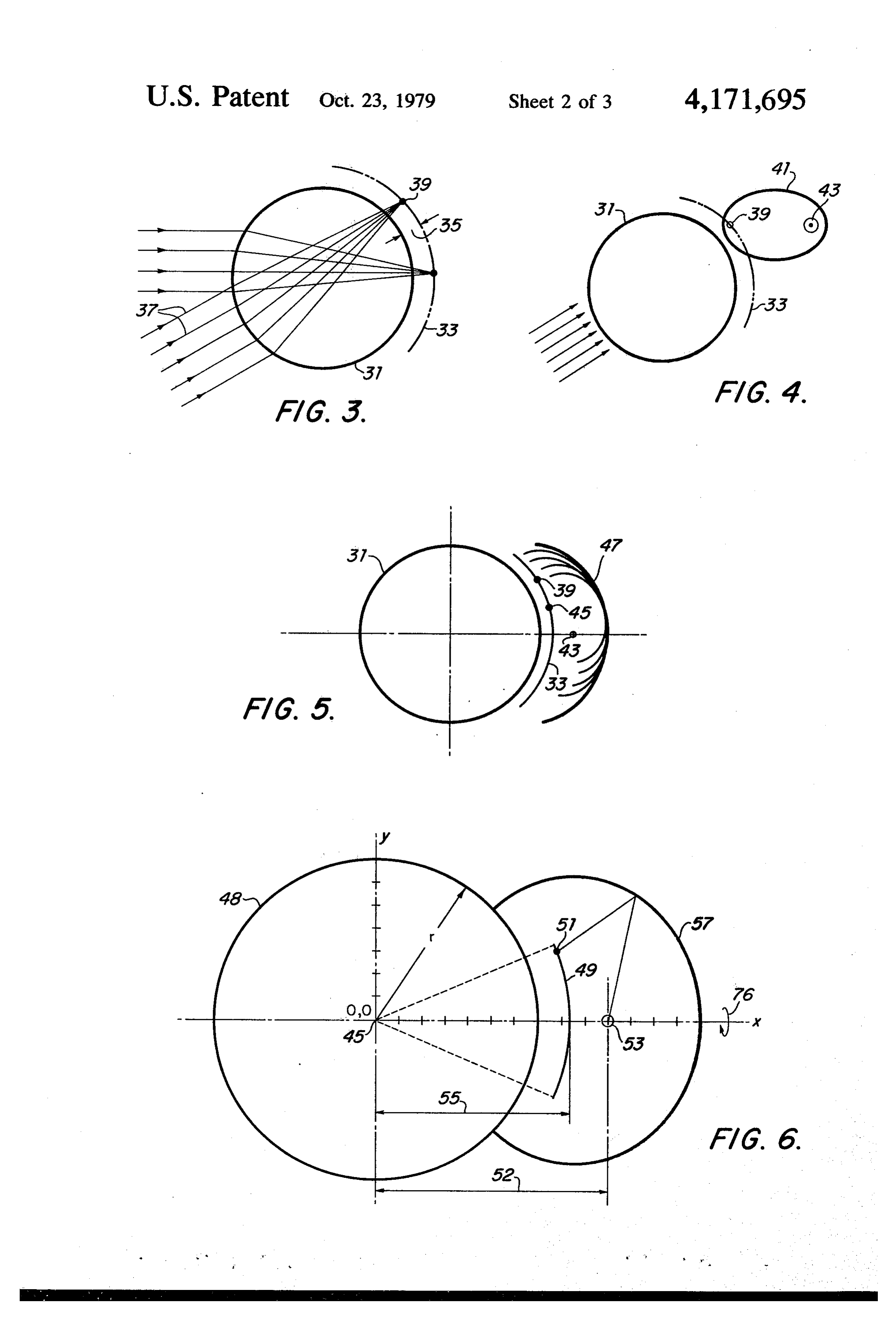
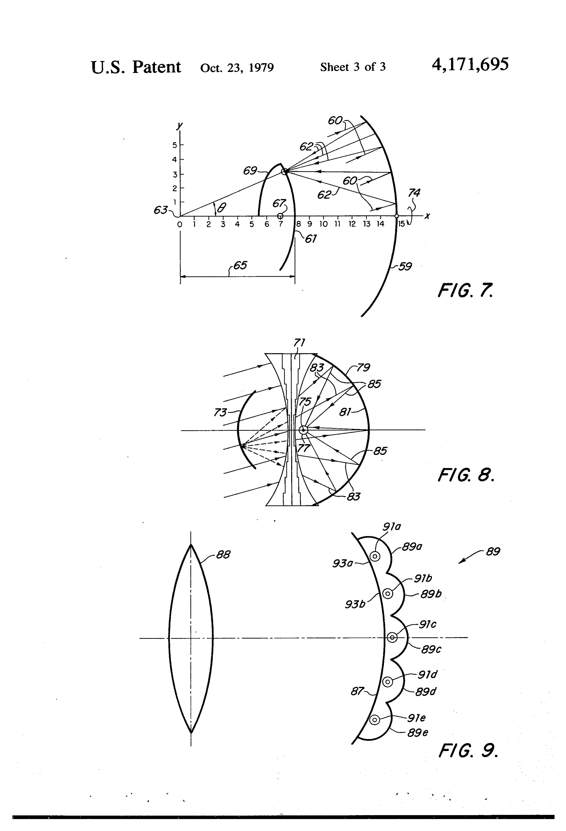
have reductions in the size of focal regions or images FIGS. 3, 4, and 5 are diagrams illustrating the method where solar energy heated liquids or other solar energy of image collapsing used in this invention. converting devices are located. These smaller tubes or FIG. 6 is a cross-sectional diagram of the present structures generally have less losses due to thermal invention employing a converging cylindrical lens. radiation than for concentrators with comparable ac FIG. 7 is a cross-sectional diagram of the present ceptance angles not employing image collapsing subre invention employing a primary reflector. flectors. The method allows for improved control of the FIG. 8 is a cross-sectional diagram of the present concentration ratios over the acceptance angle sectors invention employing a divergent cylindrical Fresnel and, for example, the concentration ratio at the edge of 10 lens.
the acceptance angle zone can be enhanced for better FIG.9 is a cross-section diagram of the present inven reception in winter. By segmenting the image collaps tion employing a segmented form of the image collaps ing subreflector into a number of contiguous image ing subreflector.
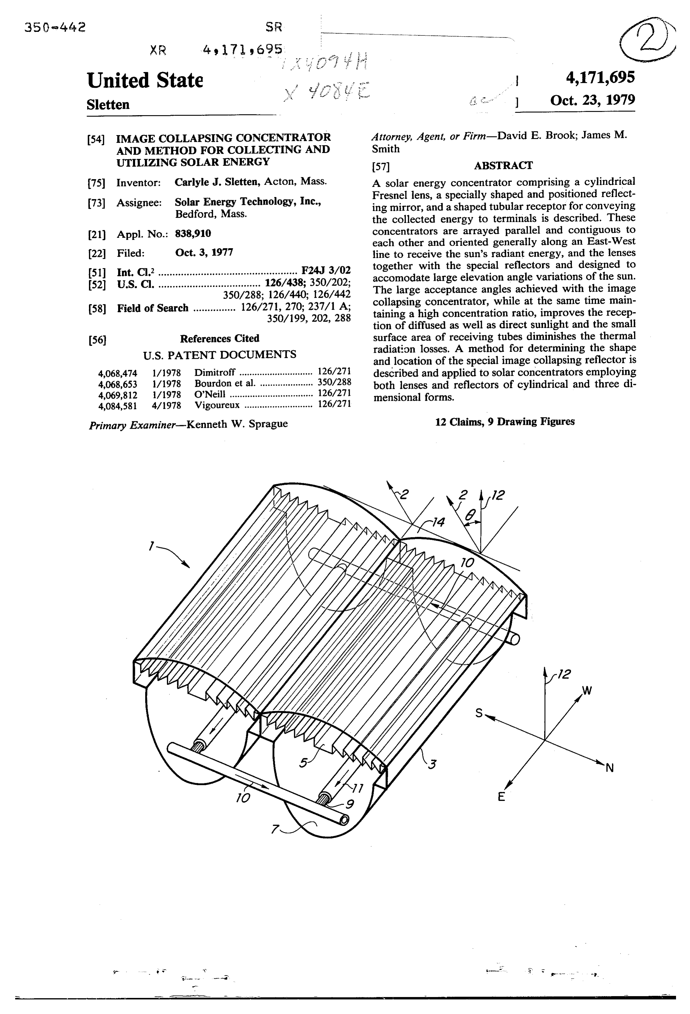
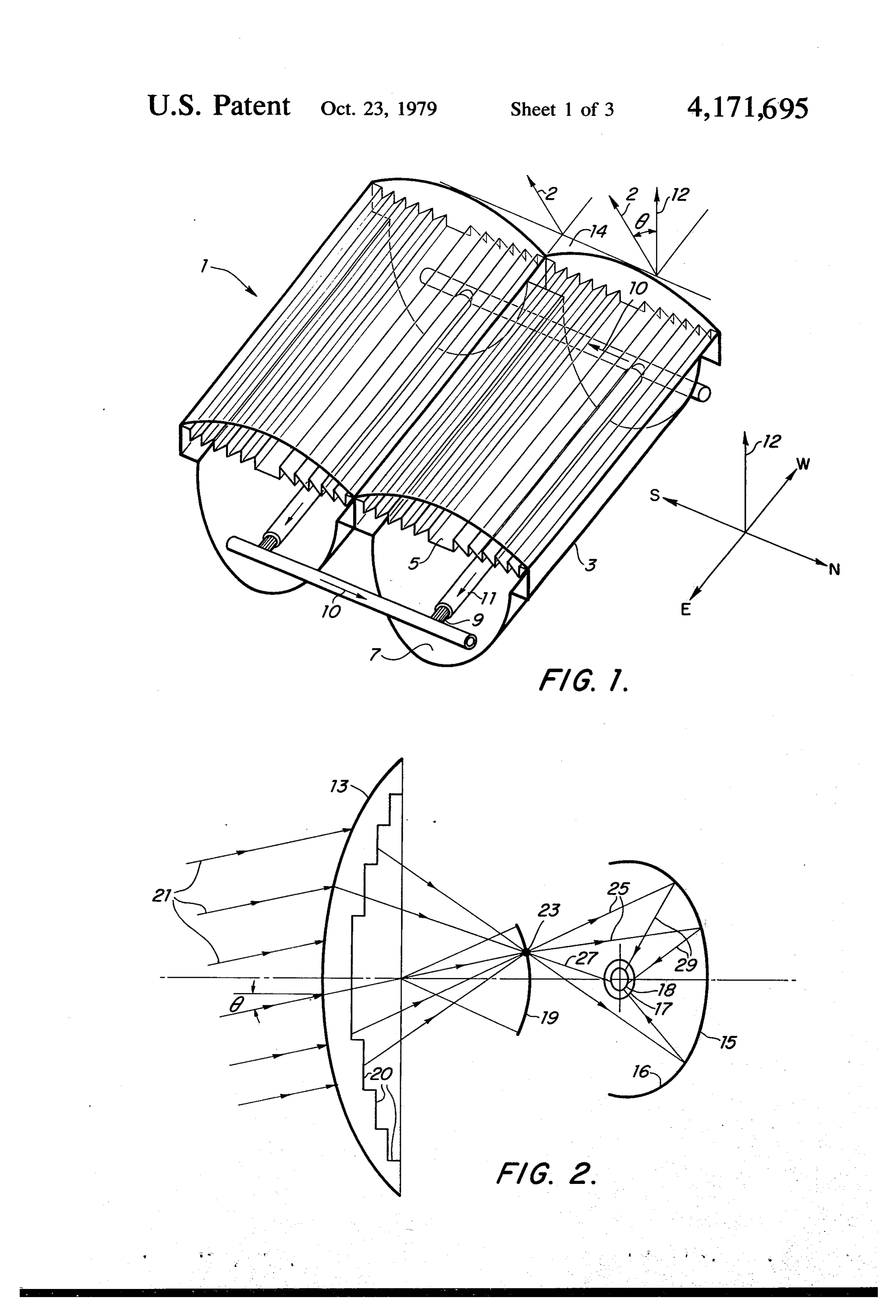
collapsing subreflectors, each operating in different DESCRIPTION OF THE PREFERRED angular sectors, higher concentration ratios can be 15 EMBODIMENTS achieved and the subreflectors can be contoured to correct for primary lens aberrations in the angular sec areReferring shown first to FIG. 1, two concentrators 1 and 3 arrayed together each having a lens 5, an tor covered by the subreflector and also compensate for the variations in focal lengths with azimuth angles especially shaped and polished subreflector 7, and a tube 9 which is surrounded by transparent evacuated which occur for dielectric lenses. The shaped volume of 0 glass the collapsed image can be occupied by shaped tubes to and 11tubing 11. The lens 5, subreflector 7 and tubings 9 are of uniform cross sections and comprise the intercept rays from all directions rather than only the cylindrical concentrator which is usually oriented such front area of the receivers as is the case when tubes are that the tube 9 and all cylindrical portions lie parallel to placed directly in the focus of primary lenses and reflec an tors. Concentrators using the image collapsing subre 25 andEast-West line represented on FIG. 1 by letters E flector are often flatter and shallower than other type tiltedW.byThe aperture plane 14 of the concentrator is some elevation angle 6 from the vertical or wide acceptance angle concentrators resulting in struc zenith direction indicated by the arrow 12 such that a tural economy. The preferred embodiments are cylin normal 2 to the aperture plane 14 is pointed generally at drical concentrators lying along an approximately East the sun at noon time. Because the elevation directions of West line on the earth with the primary focusing ele 30 the sun vary daily and seasonally, the concentrator's ment a cylindrical Fresnel lens capable of sharply focus ing in the elevation plane, sometimes known as the 2normal 2 usually is oriented in a fixed position such that is directed at the average or median position of the sun altitude direction, over an elevation angular interval of over its annual excursions. The tube 9 can be circular in from 45 to 55. cross section or of another shape cross section which is Fundamental physical limitations require that the 35 effective in intercepting rays of the sun's energy focused theoretical upper limit of concentration ratio for a con by the lens 5 directly on the tube 9 or reflected by the centrator with a given aperture area decrease as the subreflector 7 on to 9. The surface of the tube 9 is usu aceptance angle of the concentrator is increased. These ally covered with optically absorbing or black material upper limits of concentration ratio are usually not at and composed of metal when conversion of solar en tained due to deficiencies in the optical properties of the 40 ergy to heat is required or composed of electrically concentrators and other defects. By the compound active material when conversion of solar energy to focusing of this invention utilizing a focusing lens or electricity is required. Both heat and electricity can be reflector in concert with a shaped subreflector herein obtained at the same time when the tubing is both ther called an image collapsing reflector and furthermore mally and electrically active in converting sun's radiant shaping the receiving tubes to correspond to the shape 45 energy. Usually a large number of individual concentra of the final focal region, these upper limits of concentra tors are arrayed together to increase the aperture area tion ratio for a given large acceptance angular range is of the collecting systems, and the quantity of energy more nearly realized. collection. The ends of the tube 9 are usually provided A further advantage to the wide acceptance angles with tubes 10 through which oils or other liquids flow achieved by this invention is the simultaneous reception 50 as indicated by arrows to convey heat to appliances or of scattered diffuse sunlight reflected from the earth's storage for various uses such as heating buildings or surface and clouds, etc., together with the direct rays of driving steam engines.
the sun for much larger angular intervals than for track There is shown in FIG. 2 cross-sectional diagram a ing and narrow acceptance angle non-tracking concen preferred embodiment of the present invention compris trators. 55 ing a cylindrical Fresnel lens 13, an image collapsing These and other objects and advantages of this pres reflector 15 and tube 18 which is surrounded by the ent invention are more particularly set forth in the foll transparent tube 17. The lens 13 is constructed of steps lowing detailed description, the appended claims and in 20 to reduce weight and the lens material, its contours the accompanying drawings. and steps are selected and constructed to focus the BRIEF DESCRIPTION OF THE DRAWINGS direct and diffuse energy of the sun on the approxi mately circular focal arc 19 for variations of approxi
FIG. 1 is a perspective view of a deployment of the mately plus or minus 23 degrees of elevation angles 0 of present invention showing orientation of the cylindrical the sun. For each elevation angle 0 the sun's rays 21 are form of the invention with respect to azimuth and eleva focused to a point 23 from whence the rays 25 are re tion directions. 65 flected from the especially curved reflector 15 such that FIG. 2 is a diagrammatic view showing a typical the rays 29 in general intercept the tube 18 or rays such cross section of a preferred embodiment of the present as 27 directly impinge on the tube 18. An important invention. advantage of the present invention is that the surface of
Page 7
the tube 18 can be significantly smaller than the surface can show that the coordinates for image collapsing area of the focal arc 19, especially when the focal arc 19 reflector 57 can be calculated from the equations is further enlarged with tubes to convey heat collected to ports at the end of the tubes. (ci + c2) - ax
When the sun is in any position within the elevation 5 F
acceptance angles of interest from the normal 12 to the xy lens aperture plane it is the unique quality of the image y P
collapsing reflector 15 that the rays proceeding through the lens 13 and reflected from the inner surface of re when y is greater than y1 and from flector 16 will in general strike the tube 18. The tube 18 10 can be circular or elliptical in cross section but more (c1 - c.2) - a x generally its shape is determined to intercept the maxi 2c1(c. - c.2) - 2ax mum number of rays averaged over all elevation angles xyl of interest while minimizing the surface area of the tube 15 Jy = for minimum heat loss. The inner surface 16 of the re flector 15 which reflects the rays 25 onto the tube 18 when y1 is greater than y and equations of the tangent must be of polished metal of high reflectivity for optical ellipses can be calculated from energy. Suitable materials are aluminum and silver. The teachings of this invention which determine the special 20 contour of 15 are illustrated in FIGS. 3, 4, and 5 and - B - \r 4 c.
further explained by mathematical formulas and exam Jy = 2A ples.
In FIG. 3 is illustrated a simple lens 31 consisting of where a right circular cylinder of dielectric material whose 25 dielectric constant can be approximately 2.55. Such a A=(c2-y?)
lens will focus sharply on a circular focal arc 33 at a small distance 35 outside the lens on the opposite side of B= -2K21 the lens from the incident sun's rays 37 at a spot 39 or focus F. We can construct an ellipse 41 as shown in 30
FIG. 4 with one focus at 39 and another at 43. All rays passing through 39 will now be reflected by 41 to pass through 43. Because we are interested in a plurality of
sun's location and hence ray directions, the ellipse 41 or portions thereof will not focus rays to point 43 which 35 are not focused to point 39. However, as illustrated in For example, for the concentrator shown in FIG. 6, FIG. 5, when the envelope of a family of ellipses is when a = 2.2 inches c1 = 1.97 inches and c2 = 1.23 inches constructed each with one focus at 43 but with the other and the image collapsing reflector is terminated in a focus along the focal arc 33, for example point 45, the tangent ellipse for rays incident at plus and minus 23 envelop curve 47 will approximately focus all rays on 40 the coordinates of 57 can be as shown in Table I. the focal arc 33 to a small region surrounding the point Likewise, referring to FIG. 7, when the cylindrical 43. Parametric equations can be derived for the envel concentrator consists of a primary concaved cylindrical oping curve used to collapse the focal region of a lens or reflector 59 focusing the sun's ray 60 by reflected rays reflector to a small region about a point even when the 62 to a circular focal arc 61 whose radius measured focal arc of the primary lens is not a circle but some 45 from origin 63 of coordinates x and y is c1 = 7.8' as arbitrary curve, and the converging or diverging lens is shown by distance 65 when the center of tube 67 is at not a cylinder as the dielectric rod lens used in this 7.0' from the origin and c2 is 3.8 inches, then the col illustration. The examples to be given, however, clearly lapsing reflector 69 can have coordinates as given by show the utility of the method for collapsing the images Table II when for sun angles greater than plus and of either lens or reflector type solar concentrators for 50 minus 69-23 from the axis OX the reflector 69 is termi improved acceptance angles and concentration ratios. nated by the sections of ellipses with focuses at 7.0 and When coordinates x, y measured from the origin 45, as the points x1 = 6.216 and y1=2.638. shown in FIG. 6, are at the center of lens 48 that focus on circular arc 49 a distance 52 which is represented as TABLE I TABLE II c1 from the origin then an ellipse needed to focus rays 55 passing through a general point 51 with coordinates POSSIBLE COORDINATE POSSIBLE COORDINATE xyl on to point 53 can be expressed as POINTS FOR
IMAGE COLLAPSING
POINTS FOR
IMAGE COLLAPSENG
V(x-a)+y+V(x-x)+(y-yl)=c, REFLECTOR OF FEG. 6 REFLECTOR OF FIG. 7 60 x (inches) y (inches) x (inches) y (inches) where a is the distance 55 to the tube center from the 2.700 0.000 5.500 0.000
origin 45 in FIG. 6 and x1, y1 are coordinates of the 2.679 0.87 5.518 O.386 circular focal arc 49 for the special case that the primary 2.653 0.279 5.541 -0.582 lens focuses on a circle. 2.618 0.358 5.573 0.783 Therefore, x12+y 12=c12. Generally c2 has a fixed 65 2.573
value at the disposal of the designer. 2.459 0.613 5.734 1430 Differentiating the expression equaling c2 and using 2.392 0.686 5.812 1.667 the special condition that the focal arc is circular, we 2.38 0.753 5.905 1.99
Page 8
-continued tors. Therefore, point focusing reflectors are of utility TABLE I TABLE I because they usually have higher concentration ratios and less blocking than cylindrical reflectors although
POSSIBLE COORDINATE POSSIBLE COORDINATE total acceptance angles in azimuth and elevation direc POINTS FOR PONTS FOR 5 tion is generally inferior to that of cylindrical concen IMAGE COLLAPSING IMAGE COLLAPSING trators.
REFLECTOR OF FIG. 6 REFLECTOR OF FIG. 7
x (inches) y (inches) x (inches) y (inches) Likewise, when the lens of FIG. 6 focuses approxi
mately to a point and these points form a spherical 2.158 0.872 6.43 2.482 10 surface for the sun in different positions in direction 2.11 0.898 6.26 2.638 within a given solid acceptance angle surrounding the
lens axis, then the image collapsing curve calculated for 800 0.960 6,800 3.324 the cylindrical case can be rotated about the lens axis to 7.000 3.4O2 form the surface of the image collapsing reflector for a symmetric point-focusing lens, as indicated by the 15 curved arrow 76 rotating about the axis OX.
It is not necessary that the lens or reflector focus to a Referring to FIG. 9, when the primary lens 88 or circular arc but only that the coordinates of the focal reflector arc x1, y1 are known. Likewise, the constant c2 can be surface 87ofthen the concentrator produces a focal arc or the image collapsing curve 89 can be varied with the positions x1 and y1 giving another de segmented to form subreflecting mirrors 89A, 89B, 89C gree of freedom in the application of the method. In 20 and 89D. These segments are shaped using the method general the parameters a and c2 and the cross section of already described with tubes 91A, 91B, 91C and 91D the tube 67 are selected based on ray tracing experience to minimize the size region around a where rays are being located at collapsed images from sectors of the concentrated for a given acceptance angle range which, focal arc 87. This embodiment has the advantage of in the example is plus 23 to minus 23. 25 higher concentration ratios than when one image col In order to reduce the depth of the concentrator a lapsing subreflector is used for the entire focal arc 87. lens with a virtual focal surface, such as produced by a The individual subreflectors 89A-D can be shaped to divergent Fresnel lens, can be employed with an image correspond to sectors of 87 more or less in front as collapsing reflector to obtain a high concentration ratio. shown by sectors 93A, 93B of the primary focal sur In FIG. 8 is illustrated a diverging lens with focus along 30 faces and the subreflectors 89A-D can be shaped to an arc 73. The point images on the virtual image 73 can correspond to vagaries of the focal curve for each sec be chosen as focal points of a system of ellipses all of tor of the focal curve such as due to aberrations and which have a common focus point 75 which is the cen defocusing of the primary lens or reflector. In dielectric ter of a receiver tube 77. The envelope of these ellipses lenses the focal length for morning and evening azimuth 79 is the image collapsing subreflector and it can be 35 locations of the sun is different than for noon day loca constructed with polished mirror inner surface 81 tion when the sun is at the highest elevation angles. By which reflects the family of rays 83 into a small region circulating liquids through different tubes at different near 75 by means of rays 85. times of the day the concentrator can be adjusted for Although cylindrical or two dimensional reflectors these variations. Switching by proper hourly program and lens are frequently employed for solar energy appli ming from tubes 91A through 91D or, of course, for cations because they usually focus to a line for all azi larger or smaller segments over any focal surface will muth (East-West motion) angles of the sun, point-focus result in better aperture efficiencies, higher concentra ing or three dimensional lens systems are also of utility. tion ratios, and higher temperatures than when only one The image collapsing method described for cylindrical image collapsing subreflector is employed. systems can be extended to point-focusing lenses and 45 After the shape and position of the collapsing mirror reflectors which can best be described in three dimen has been calculated using the analytical procedures and sional coordinates y, x, and Z. An ellipsoid generating equation herein described, the performance of the con function centrator can be examined by tracing rays using laser V(x-a)+y+z’+V(x-x1)+(y-yl)- rays for example, or by analytic determination or ray +(y-z1) = c2 50 path using Snell's law at surfaces and boundaries of the lenses and reflectors. The geometric region spot size can be defined and focal surface X1, y1, Z1 collapsed to a where the majority of rays are intercepted (within the smaller region around the point x=a, y = z = 0. For desired acceptance angles of the concentrator) deter example, when the curve 59 of FIG. 7 is a circle form mines the tube size and tube shape. Also, the parameters ing a concave reflector, it can be rotated about the axis 55 of the primary lens or reflector and the values of a and OX as indicated by arrow 74 to form a spherical cap c2 of the image collapsing reflector can all be varied to rather than a cylindrical reflector as previously de reduce the spot size and the cross-sectional area of the scribed. Likewise, due to the symmetry of a sphere, the receiver tube located within this region. focal curve 61 and the image collapsing reflector 69 can Those skilled in the art will recognize, or be able to be rotated also about OX and the resulting shapes will ascertain using no more than routine experimentation, focus the energy incident on the spherical cap whose many equivalents to the specific elements described cross section is 59 on to a small region 67 around point herein. Such equivalents are intended to be covered by a. the following claims.
The blocking of a subreflector in front of a primary What is claimed is:
reflector reduces the aperture efficiency of the concen 65 1. In a solar energy concentrator having a primary trator. Such blocking is absent for lens type concentra optically focusing component and a tubular receptor tors and is generally less for point-focusing reflectors and wherein said priary optically focusing component than for cylindrical line focusing reflector concentra focuses incident radiation onto said tubular receptor,
Page 9
the improvement of additionally providing in said con 7. A concentrator constructed in accordance with centrator a subreflector designed to collapse the image claim 1 wherein the concentrator consists of a reflector size from the primary optically focusing component which focuses the sun's rays to a small spot and whose wherein said subreflector has a shape conforming to the focal surface generated by a range of different elevation mathematical principle of envelopes using a family of 5 and azimuth angular positions of the sun is collapsed by an especially shaped and positioned image collapsing ellipses or ellipsoids as generating curves.
2. A concentrator in accordance with claim 1 subreflector onto an especially shaped collecting sur wherein the concentrator consists of a primary optical face.
focusing component in the form of a converging Fres 10 8. A concentrator constructed in accordance with nel lens and a shaped image collapsing subreflector optical claim 1 wherein the concentrator consists of a primary whose reflecting surface is shaped according to the and a shaped focusing component producing a focal surface image collapsing subreflector whose form envelop of a family of titled ellipses or ellipsoids each of is segmented into which focuses on a common region and also on portions of which is contoured contiguous shaped subreflectors each after the envelop of a system of of the primary focal region of the converging Fresnel 15 titled ellipses or ellipsoids to collapse a portion of the lens, and a collecting tube whose shape is determined by image of the primary optical focusing component onto the location of the maximum density of ray reflected by a small shaped region containing a tube whose shape the image collapsing subreflector and whose surface is conforms to the contours of the collapsed focal region blackened to absorb sunlight and which shaped tube is produced by each segment of the image collapsing surrounded by an evacuated glass tubing such that a 20 subreflector; the improvement of additionally providing partial vacuum reduces heat losses from the heated segmented forms of the image collapsing subreflector tube. being to further reduce the size of the energy convert 3. A concentrator in accordance with claim 1 ingard collecting tubes in order to increase the concen wherein the concentrator consists of a diverging Fres tration ratio of the concentrator and its operating tem nel lens as the primary optical focusing component and 25 peratures. .
a shaped image collapsing subreflector and a shaped 9. The concentrator of claim 8 wherein each tube in collecting tube whose surface is blackened to absorb the focal region of the collapsed images of the segments sunlight and which shaped tube is surrounded by an of the image collapsing subreflector is switched into or evacuated glass tubing such that a partial vacuum re out of a collecting system connected to the terminals of duces heat losses from the heated tube. 30 each tube consisting of flowing liquids heated by the 4. A concentrator in accordance with claim 1 concentrator and delivered to terminals utilizing the wherein the concentrator consists of a lens as the pri heat collected, such sequence of switching being done mary optical focusing component in the form of a right inswitching order to bring the sun's rays onto the tube or tubes circular cylinder of dielectric with dielectric constant 35 the day orinto the collecting systems for a given hour of season of the year.
which can be 2.55 and a shaped image collapsing subre flector and a shaped collecting tube whose surface is the10.steps A method of collecting solar energy comprising
blackened to absorb sunlight and which shaped tube is focusing solar rays into an image by means of a pri surrounded by an evacuated glass tubing such that a mary wide angle, optically focusing component, partial vacuum reduces heat losses from the heated and tube. collapsing the image from the primary component 5. A concentrator in accordance with claim 1 onto a receiving element by means of a subreflector wherein the primary optically focusing component con having a shape conforming to the mathematical sists of primary reflector in the form of a concaved principle of envelopes with a family of ellipses or circular cylinder. 45 ellipsoids as generating curves. 6. A concentrator constructed in accordance with 11. A method of collecting solar energy as claimed in claim 1 wherein the concentrator consists of a lens as claim 10 wherein the primary optically focusing compo the primary focusing component which focuses the nent and the subreflector are of cylindrical form. sun's rays to a small spot and whose focal surface gener 12. A method of collecting solar energy as claimed in ated for a range of azimuth and elevation angles is col 50 claim 10 wherein the primary optically focusing compo lapsed by an image collapsing shaped subreflector to a nent and subreflector face toward the average position shaped collecting surface smaller than the primary focal of the noontime sun.
surface.
Provenance
- Collection
- Cited prior art
- Original PDF
- patentimages.storage.googleapis.com →
- Filed
- 1977-10-03
- Pages
- 9
- Method
- pdftotext (the PDF's own text layer) + pdftoppm 300dpi page scans
- Source
- Google Patents bibliographic record
- Granted
- 1979-10-23
- Inventors
- Carlyle J. Sletten; SOLAR ENERGY Tech Inc
- Transcribed from
- patentimages.storage.googleapis.com →