patent · US5059013
Illumination system to produce self-luminous light beam of selected cross-section, uniform intensity and selected numerical aperture
22 October 1991
Page 1 — bibliographic record
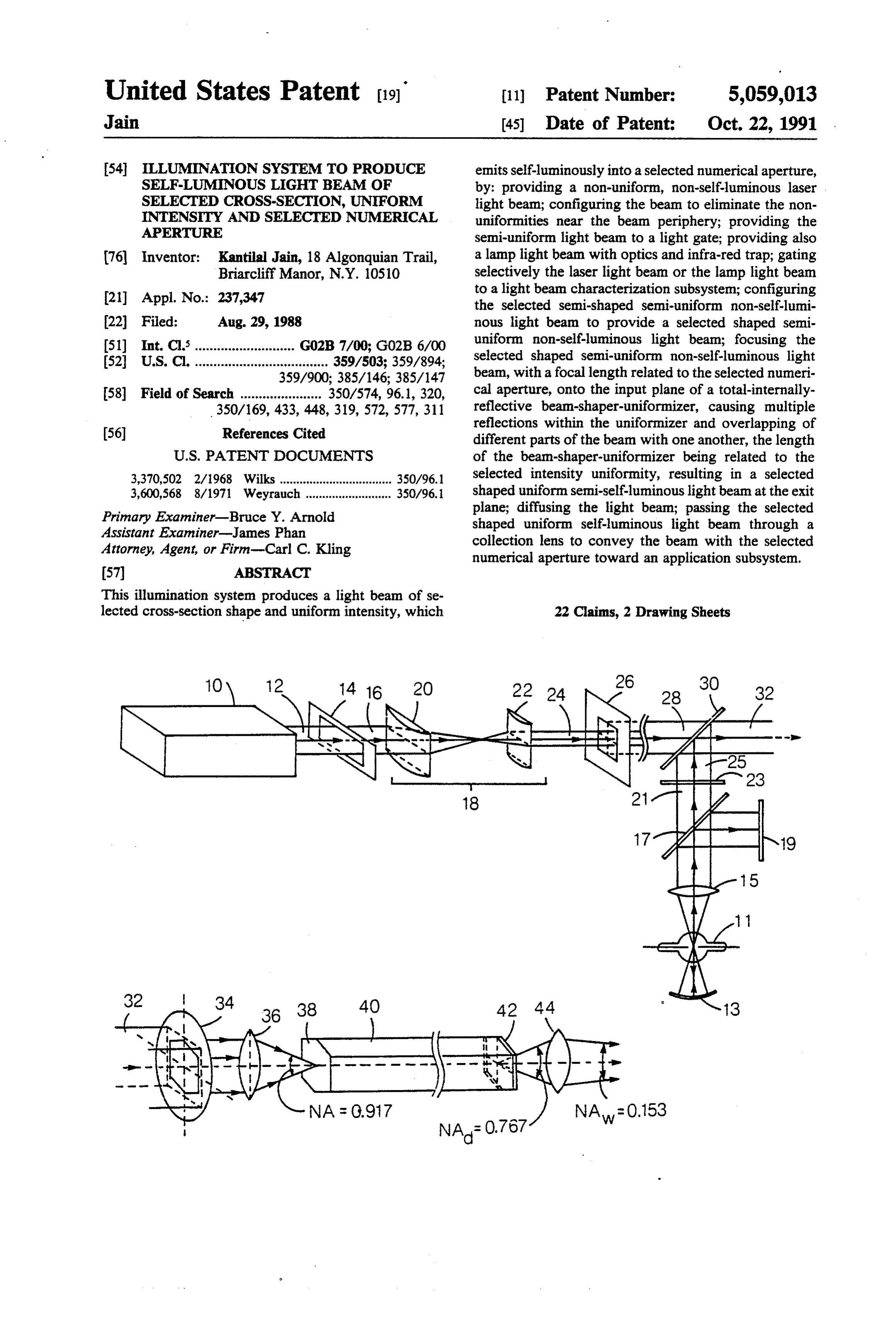
United States Patent (19) 11) Patent Number: 5,059,013 Jain 45 Date of Patent: Oct. 22, 1991 54 ILLUMINATION SYSTEM TO PRODUCE emits self-luminously into a selected numerical aperture, SELF-LUMNOUS LIGHT BEAM OF by: providing a non-uniform, non-self-luminous laser SELECTED CROSS-SECTION, UNIFORM light beam; configuring the beam to eliminate the non INTENSTY AND SELECTED NUMERICAL uniformities near the beam periphery; providing the APERTURE semi-uniform light beam to a light gate; providing also 76 Inventor: Kantilal Jain, 18 Algonquian Trail, a lamp light beam with optics and infra-red trap; gating Briarcliff Manor, N.Y. 10510 selectively the laser light beam or the lamp light beam 21 Appl. No.: 237,347 to a light beam characterization subsystem; configuring the selected semi-shaped semi-uniform non-self-lumi 22 Filed: Aug. 29, 1988 nous light beam to provide a selected shaped semi 51) Int. Cl............................ G02B 7/00; G02B6/00 uniform non-self-luminous light beam; focusing the 52 U.S. C. .................................... 359/503; 359/894; selected shaped semi-uniform non-self-luminous light 359/900; 385/146; 385/147 beam, with a focal length related to the selected numeri 58 Field of Search ...................... 350/574, 96.1, 320, cal aperture, onto the input plane of a total-internally 350/169, 433,448, 319,572, 577, 311 reflective beam-shaper-uniformizer, causing multiple
reflections within the uniformizer and overlapping of different parts of the beam with one another, the length
3,370,502 2/1968 Wilks .................................. 350/96.1 selected intensity uniformity, resulting in a selected 3,600,568 8/1971 Weyrauch .......................... 350/96.1 shaped uniform semi-self-luminous light beam at the exit Primary Examiner-Bruce Y. Arnold plane; diffusing the light beam; passing the selected
Assistant Examiner-James Phan shaped uniform self-luminous light beam through a Attorney, Agent, or Firm-Carl C. Kling collection lens to convey the beam with the selected numerical aperture toward an application subsystem.
This illumination system produces a light beam of se lected cross-section shape and uniform intensity, which 22 Claims, 2 Drawing Sheets
Page 2
Drawing sheet — no readable text.
Page 3
Drawing sheet — no readable text.
Page 4
formity, and providing uniformization in the light beam
ILLUMINATION SYSTEM TO PRODUCE characterization subsystem through some artifice such SELF-LUMNOUS LIGHT BEAM OF SELECTED as a fly’s-eye lens, diffuser or rotating mirror. CROSS-SECTION, UNIFORM INTENSITY AND An approach of the prior art is to use some efficient SELECTED NUMERICAL APERTURE 5 source of light, such as a halogen lamp with optics, or a laser, as a primary light source. This typically produces
BACKGROUND OF THE INVENTION a collimated light beam. Typically, a diffuser plate 1. Field of the Invention etched to a degree of roughness is used to provide the This invention relates to light beam illumination sys 10 desired uniformity property.
tems, and more particularly relates to method and appa Another approach of the prior art is to use a fly’s-eye ratus for producing a light beam of selected cross-sec lens to provide the uniformity property to the beam. tion shape and uniform intensity, and which emits self The fly’s-eye lens is a multiple lens array, which essen luminously into a selected numerical aperture. tially replicates the scene hundreds of times, and can 2. Description of the Prior Art thus scatter the light so as to replicate the point source Precision illumination systems are used extensively in 15 hundreds of times and thus provide the uniformity the production of integrated circuit chips and electronic property. Note that the fly’s-eye lens is thus essentially circuit boards. Such illumination systems typically in used as a diffuser.
clude a primary light source such as a high intensity Another approach of the prior art is to use a concen lamp or a laser; a target positioning system; a protection trated light beam from a primary source, but to scan the system to illuminate the target with the selected pattern; concentrated light beam across the desired cross-section and a control system. The intent typically is to illumi by using a rotating mirror. nate a chip covered with a photoactive layer so as to The artifices used to provide the self-luminous prop produce the desired circuit pattern, which later will be erty have tended to reduce efficiency. There has been a metallized or otherwise activated during further pro cessing. Illumination may be by ultraviolet light, visible 25 continuing need for improvement in illumination sys light, electron-beam or a combination spectrum of radi ters.
ation. The desire is to illuminate the target chip selec SUMMARY OF THE INVENTION tively, so as to activate a particular pattern. Integrated circuit chips typically undergo several illumination The object of the invention is to provide an illumina steps during production. tion system producing a light beam, of selected cross The high resolution illumination systems used in such section and uniform intensity, which emits self-lumi applications as semiconductor integrated circuit pro nously into a selected numerical aperture of emission. duction, and in production of electronic circuit boards, A feature of the invention is the focusing of the light use or high-intensity lamps or lasers as producers of beam into a cylindrical beam-shaper-uniformizer of primary light beams and may employ lens systems to 35 polygonal cross-section and with internally reflecting expand the primary beams into beams of the desired surfaces, the focal length of the focusing lens being shape and intensity. The expanded light beans may selected to provide the selected numerical aperture and however not be of uniform intensity when expanded. If the beam-shaper-uniformizer providing the self-lumi derived from a laser source or via collimating lens sys nance and unifornity property.
tems, the beam may be collimated and thus lack the 40 Another feature of the invention is the provision of self-luminance property which many applications de multiple light sources, each to provide a light beam mand. selectively, via a flip-mirror gate system to a common Uniformation of the light beam transverse interisity optical train including focusing lens and beam-shaper distribution has in the prior art been approached by unifornizer.
such light scattering artifices as a fly’s-eye lens, a dif 45 Another feature is the method of providing a light fuser or a rotating mirror. beam for industrial patterning, using steps designed to Self luminance is the characteristic of unifornity of accept light from a light beam source subsystem in multi-directional light emissivity at all points across a collimated form and to configure and render the light light beam.
The self-luminance property of an illumination sys 50 beam merical uniform and self-luminous, with the selected nu aperture, in a light beam characterization sub tem is such that any point across the beam emits into a system. An range of directions, in a core which may be described in it accepts anadvantage of the illumination system is that terms of a numerical aperture. Collimated light, that is, self luminousundesirably light beam shaped, non-uniform and non from an appropriately selected light which is not scattered but in which each ray is light source subsystem and forwards the light beam via parallel to the beam axis, provided when a laser is the 55 an efficient light beam characterization subsystem primary light source. A collimated light beam from a laser is not self-luminous. Light from certain high-inten which shapes and uniformizes the light beam and adds sity lamps may be collimated be associated reflection the self-luminance property as required by utilization apparatus.
and lens systems and thus is not self-luminous.
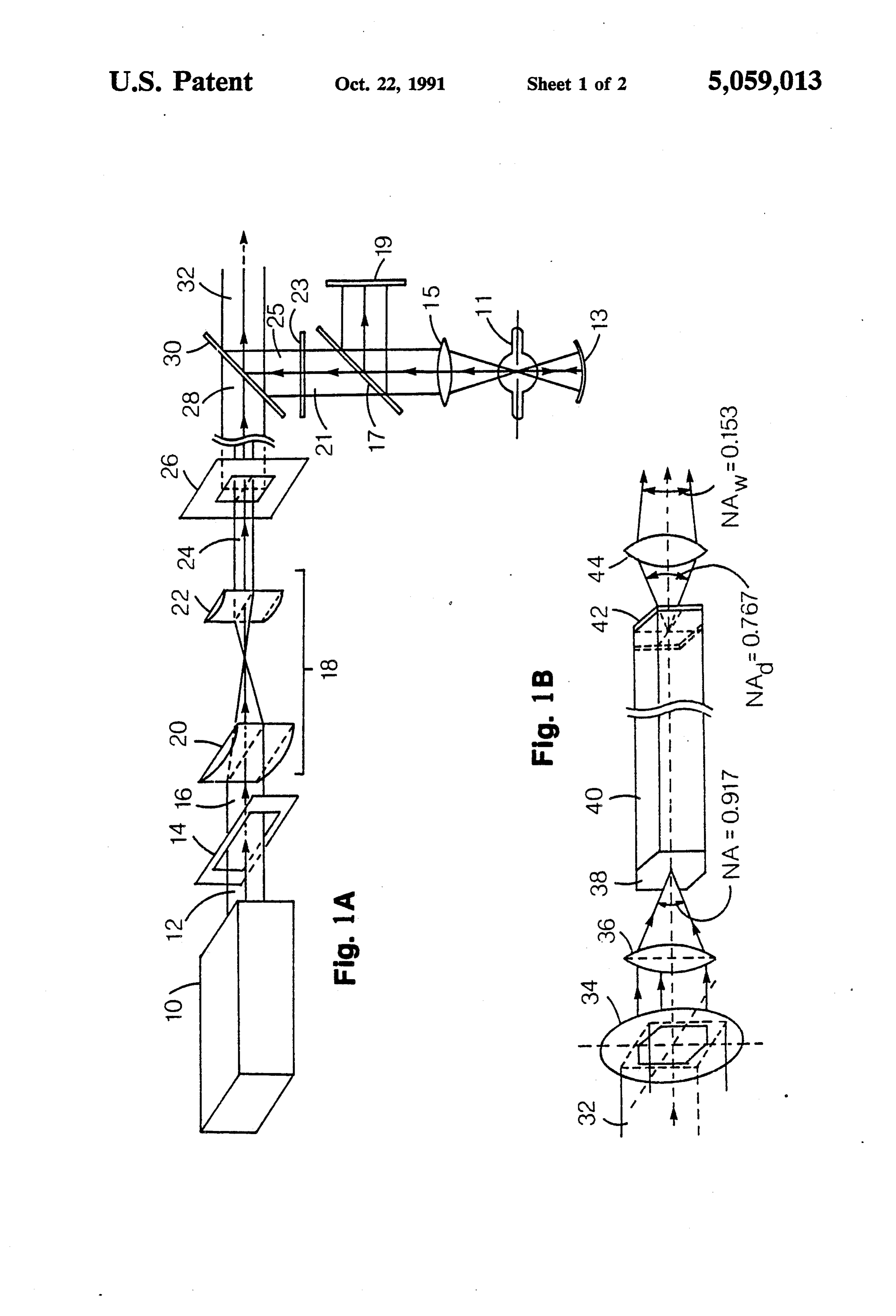
The varying demands of industrial applications of 60 BRIEF DESCRIPTION OF THE DRAWINGS illumination systems are best served by an illumination systems which efficiently produces a light beam of de FIG. 1A is a diagram illustrating the light beam sired wavelength and cross-section shape, having the source subsystem. This subsystem includes a multiple property of uniform intensity distribution across the primary light source which provides a semi-shaped cross-section, and having the self-luminance property 65 light beam alternatively from a laser source or a short with a desired numerical aperture of emission. These arc lamp to a selecting light gate. An excimer laser with demands have typically been approached by using a transforming optics provides a semi-shaped light beam primary light source subsystem which is lacking in uni at the light gate; a short-arc lamp with reflector and
Page 5
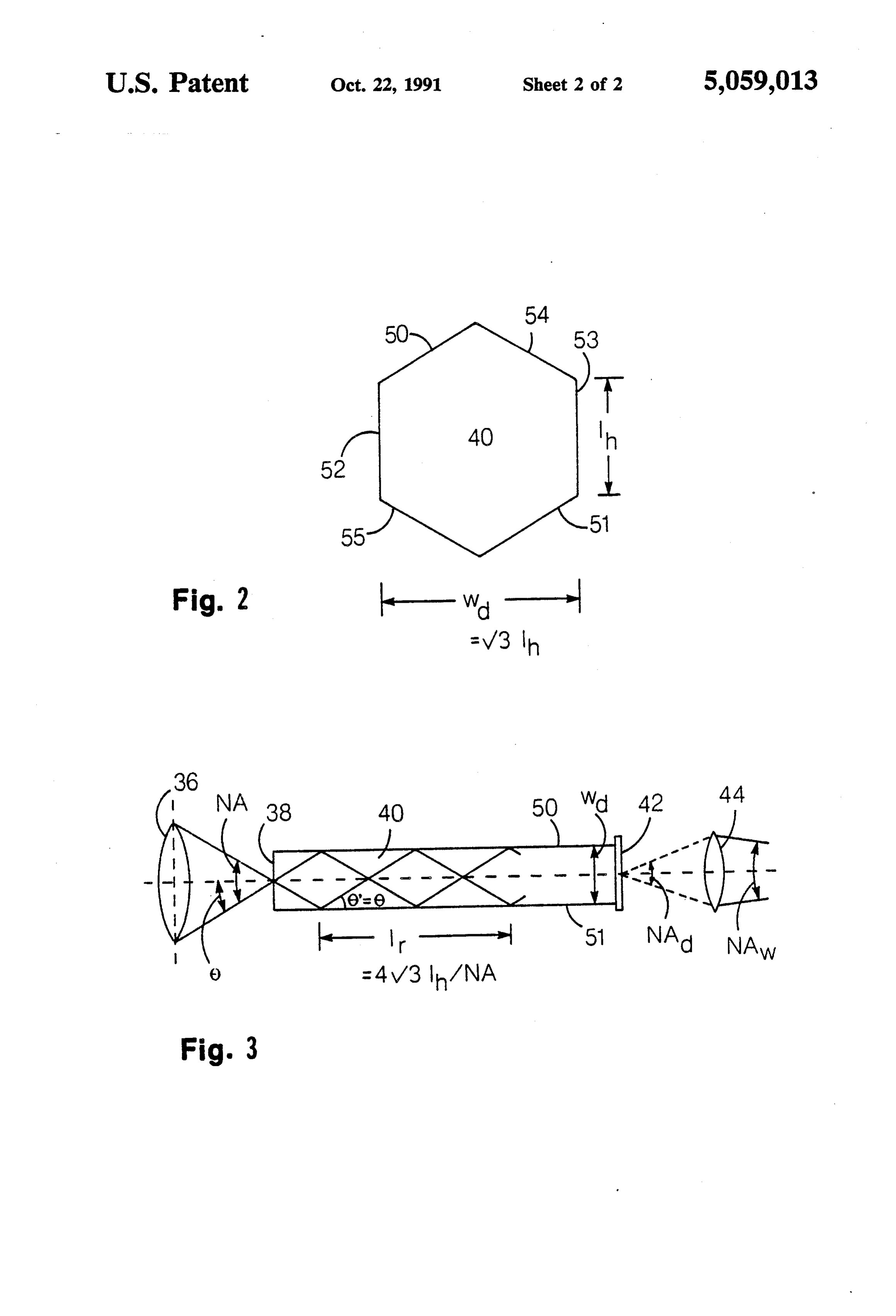
collimating lens provides a second semi-shaped light essentially point sources or extended point sources, such beam at the light gate. as a laser with a gaussian beam or a short-arc lamp, a FIG. 1B is a diagram illustrating the light beam char collimating lens is used to produce a collimated beam acterization subsystem. The continuation of the optical with a circular cross-section.
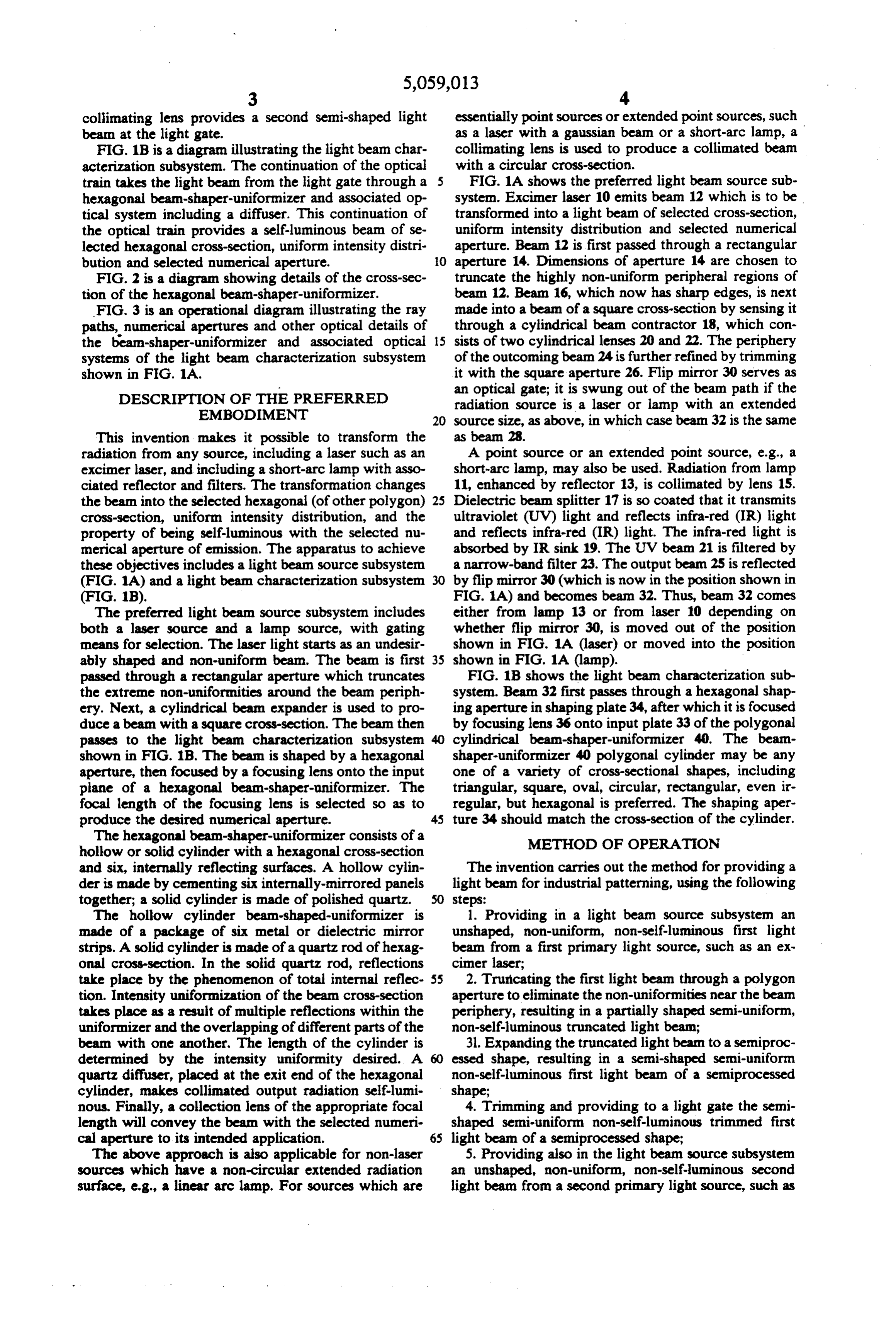
train takes the light beam from the light gate through a FIG. 1A shows the preferred light beam source sub hexagonal beam-shaper-uniformizer and associated op system. Excimer laser 10 emits beam 12 which is to be tical system including a diffuser. This continuation of transformed into a light beam of selected cross-section, the optical train provides a self-luminous beam of se uniform intensity distribution and selected numerical lected hexagonal cross-section, uniform intensity distri aperture. Beam 12 is first passed through a rectangular bution and selected numerical aperture. O aperture 14. Dimensions of aperture 14 are chosen to FIG. 2 is a diagram showing details of the cross-sec truncate the highly non-uniform peripheral regions of tion of the hexagonal beam-shaper-uniformizer. beam 12. Beam 16, which now has sharp edges, is next FIG. 3 is an operational diagram illustrating the ray made into a beam of a square cross-section by sensing it paths, numerical apertures and other optical details of through a cylindrical beam contractor 18, which con the beam-shaper-uniformizer and associated optical 15 sists of two cylindrical lenses 20 and 22. The periphery systems of the light beam characterization subsystem of the outcoming bean 24 is further refined by trimming shown in FIG. 1A. it with the square aperture 26. Flip mirror 30 serves as DESCRIPTION OF THE PREFERRED an optical gate; it is swung out of the beam path if the EMBODIMENT radiation source is a laser or lamp with an extended source size, as above, in which case beam 32 is the same
This invention makes it possible to transform the as beam 28.
radiation from any source, including a laser such as an A point source or an extended point source, e.g., a excimer laser, and including a short-arc lamp with asso short-arc lamp, may also be used. Radiation from lamp ciated reflector and filters. The transformation changes 11, enhanced by reflector 13, is collimated by lens 15. the beam into the selected hexagonal (of other polygon) 25 Dielectric beam splitter 17 is so coated that it transmits cross-section, uniform intensity distribution, and the ultraviolet (UV) light and reflects infra-red (IR) light property of being self-luminous with the selected nu and reflects infra-red (IR) light. The infra-red light is merical aperture of emission. The apparatus to achieve absorbed by IR sink 19. The UV beam 21 is filtered by these objectives includes a light beam source subsystem a narrow-band filter 23. The output beam 25 is reflected (FIG. 1A) and a light beam characterization subsystem 30 by flip mirror 30 (which is now in the position shown in (FIG. 1B). FIG. 1A) and becomes beam 32. Thus, beam 32 comes The preferred light beam source subsystem includes either from lamp 13 or from laser 10 depending on both a laser source and a lamp source, with gating whether flip mirror 30, is moved out of the position means for selection. The laser light starts as an undesir shown in FIG. 1A (laser) or moved into the position ably shaped and non-uniform beam. The beam is first 35 shown in FIG. 1A (lamp).
passed through a rectangular aperture which truncates FIG. 1B shows the light beam characterization sub the extreme non-unifornities around the beam periph system. Beam 32 first passes through a hexagonal shap ery. Next, a cylindrical beam expander is used to pro ing aperture in shaping plate 34, after which it is focused duce a beam with a square cross-section. The beam then by focusing lens 36 onto input plate 33 of the polygonal passes to the light beam characterization subsystem cylindrical beam-shaper-unifornizer 40. The beam shown in FIG. 1B. The beam is shaped by a hexagonal shaper-unifornizer 40 polygonal cylinder may be any aperture, then focused by a focusing lens onto the input one of a variety of cross-sectional shapes, including plane of a hexagonal beam-shaper-uniformizer. The triangular, square, oval, circular, rectangular, even ir focal length of the focusing lens is selected so as to regular, but hexagonal is preferred. The shaping aper produce the desired numerical aperture. 45 ture 34 should match the cross-section of the cylinder. The hexagonal beam-shaper-uniformizer consists of a METHOD OF OPERATION hollow or solid cylinder with a hexagonal cross-section and six, internally reflecting surfaces. A hollow cylin The invention carries out the method for providing a der is made by cementing six internally-mirrored panels light beam for industrial patterning, using the following together; a solid cylinder is made of polished quartz. steps:
The hollow cylinder beam-shaped-uniformizer is 1. Providing in a light beam source subsystem an made of a package of six metal or dielectric mirror unshaped, non-uniform, non-self-luminous first light strips. A solid cylinder is made of a quartz rod of hexag beam from a first primary light source, such as an ex onal cross-section. In the solid quartz rod, reflections cimer laser;
take place by the phenomenon of total internal reflec 55 2. Truricating the first light beam through a polygon tion. Intensity uniformization of the beam cross-section aperture to eliminate the non-uniformities near the beam takes place as a result of multiple reflections within the periphery, resulting in a partially shaped semi-uniform, uniformizer and the overlapping of different parts of the non-self-luminous truncated light bean; beam with one another. The length of the cylinder is 31. Expanding the truncated light beam to a semiproc determined by the intensity uniformity desired. A essed shape, resulting in a semi-shaped semi-uniform quartz diffuser, placed at the exit end of the hexagonal non-self-luminous first light beam of a semiprocessed cylinder, makes collimated output radiation self-lumi shape;
nous. Finally, a collection lens of the appropriate focal 4. Trimming and providing to a light gate the semi length will convey the beam with the selected numeri shaped semi-uniform non-self-luminous trimmed first cal aperture to its intended application. 65 light beam of a semiprocessed shape; The above approach is also applicable for non-laser 5. Providing also in the light beam source subsystem sources which have a non-circular extended radiation an unshaped, non-uniform, non-self-luminous second surface, e.g., a linear arc lamp. For sources which are light beam from a second primary light source, such as
Page 6
a halogen lamp with optics and infra-red trap, resulting sin (NA/2).
in a semi-shaped semi-uniform non-self-luminous sec ond light beam of a semiprocessed shape; As also shown in FIG. 3, a ray travels a distance 1, 6. Providing to the light gate the semi-shaped semi given by uniform non-self-luminous second light beam of a semi processed shape;
7. Operating the light gate selectively to pass selec Note that this equation omits the term Cosine Theta, tively from the light beam source subsystem the first or which for working purposes is approximated at " Co the second semi-shaped semi-uniform non-self-luminous sine value= unity" because the angle is so small. Light light beam to a light beam characterization subsystem; rays that travel
in planes other than those that are per 8. Passing the selected semi-shaped semi-uniform pendicular to pairs of reflecting surfaces, and thus have non-self-luminous light beam through a final shaping different path lengths, might be perceived as having a aperture to provide a selected shaped semi-uniform coma-like effect at surface 42, but this is academic only. non-self-luminous light beam;
9. Focusing the selected shaped semi-uniform non 15 Any such coma-like effect would be completely nonde self-luminous light beam, with a focal length related to trimental, since there is no imaging taking place in the the desired numerical aperture, onto the input plane of system in the functioning of the invention. Light rays a total-internally-reflective polygon-cylindrical beam having differing path lengths, however, contribute to shaper-uniformizer, causing multiple reflections within the overlapping between various rays and improve the uniformization. The thorough mixing between rays the uniformizer and overlapping of different parts of the 20 entering the hexagonal cylinder at different angles in beam with one another, the length of the polygon-cylin proves performance as uniformizer. drical beam-shaper-uniformizer being related to the The beam uniformity finally achieved depends on the desired intensity uniformity, resulting in a selected shaped uniform semi-self-luminous light beam at the exit 25 number of internal reflections, which, in turn, deter mines the length L of the hexagonal beam-shaper-uni plane;
10. Passing the selected shaped uniform semi-self formizer 40. For example, if N internal reflections are luminous light bean through a diffuser to provide a desired, the length should be selected shaped uniform self-luminous light beam; and 11. Passing the selected shaped uniform self-luminous light beam through a collection lens to convey the beam 30 In a solid cylinder made of a material of refractive with the selected numerical aperture toward an applica index n, the ray angle within the cylinder is given by tion subsystem.
Some steps, particularly those involving lenses and sin 0=n sin 0", i.e., 8'=sin (NA/2n). those involving aperture plates, may be combined where the application permits. 35
In this case, l. given by
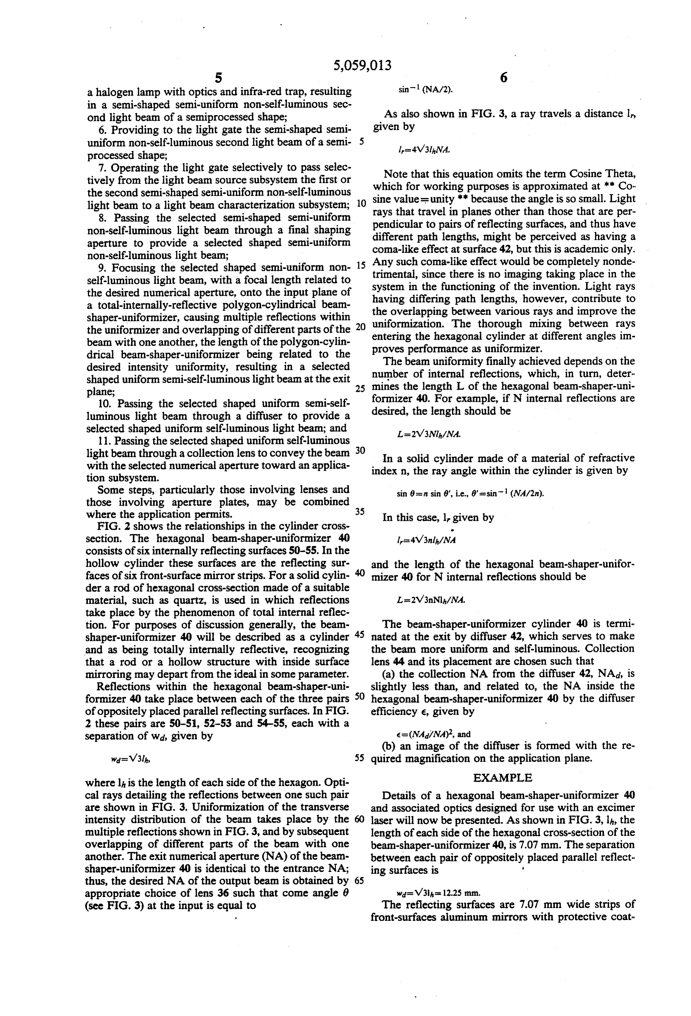
FIG. 2 shows the relationships in the cylinder cross section. The hexagonal beam-shaper-uniformizer 40 consists of six internally reflecting surfaces 50-55. In the hollow cylinder these surfaces are the reflecting sur and the length of the hexagonal beam-shaper-unifor faces of six front-surface mirror strips. For a solid cylin mizer 40 for N internal reflections should be der a rod of hexagonal cross-section made of a suitable material, such as quartz, is used in which reflections take place by the phenomenon of total internal reflec tion. For purposes of discussion generally, the beam The beam-shaper-uniformizer cylinder 40 is termi shaper-uniformizer 40 will be described as a cylinder 45 nated at the exit by diffuser 42, which serves to make and as being totally internally reflective, recognizing the beam more uniform and self-luminous. Collection that a rod or a hollow structure with inside surface lens 44 and its placement are chosen such that mirroring may depart from the ideal in some parameter. (a) the collection NA from the diffuser 42, NAd, is Reflections within the hexagonal beam-shaper-uni 50 slightly less than, and related to, the NA inside the formizer 40 take place between each of the three pairs hexagonal beam-shaper-uniformizer 40 by the diffuser of oppositely placed parallel reflecting surfaces. In FIG. efficiency e, given by
separation of wal, given by e=(NA/NA), and (b) an image of the diffuser is formed with the re 55 quired magnification on the application plane.
where lh is the length of each side of the hexagon. Opti EXAMPLE cal rays detailing the reflections between one such pair Details of a hexagonal beam-shaper-uniformizer 40 are shown in FIG. 3. Uniformization of the transverse and associated optics designed for use with an excimer intensity distribution of the beam takes place by the 60 laser will now be presented. As shown in FIG. 3, h, the multiple reflections shown in FIG. 3, and by subsequent length of each side of the hexagonal cross-section of the overlapping of different parts of the beam with one beam-shaper-uniformizer 40, is 7.07 mm. The separation another. The exit numerical aperture (NA) of the beam between each pair of oppositely placed parallel reflect shaper-uniformizer 40 is identical to the entrance NA; ing surfaces is 8 thus, the desired NA of the output beam is obtained by 65 appropriate choice of lens 36 such that come angle 6 wa=v31 = 12.25 mm.
(see FIG. 3) at the input is equal to The reflecting surfaces are 7.07 mm wide strips of front-surfaces aluminum mirrors with protective coat
Page 7
ing for the UV radiation of the excimer laser. Aperture numerical aperture, said light beam characterization 34 has the same directions as the cross-section described subsystem comprising:
above, the maximum extent of the input beam from top (a) beam shaping means (34, FIG. 1B), optically re to bottom thus being 21- 14.14 mm. Lens 36 is de lated to the selected cross-section shape, optically signed for an input NA of 0.917; thus, with a clear aper associated with said primary light source subsys ture of 14.14 mm diameter, its focal length is tem;
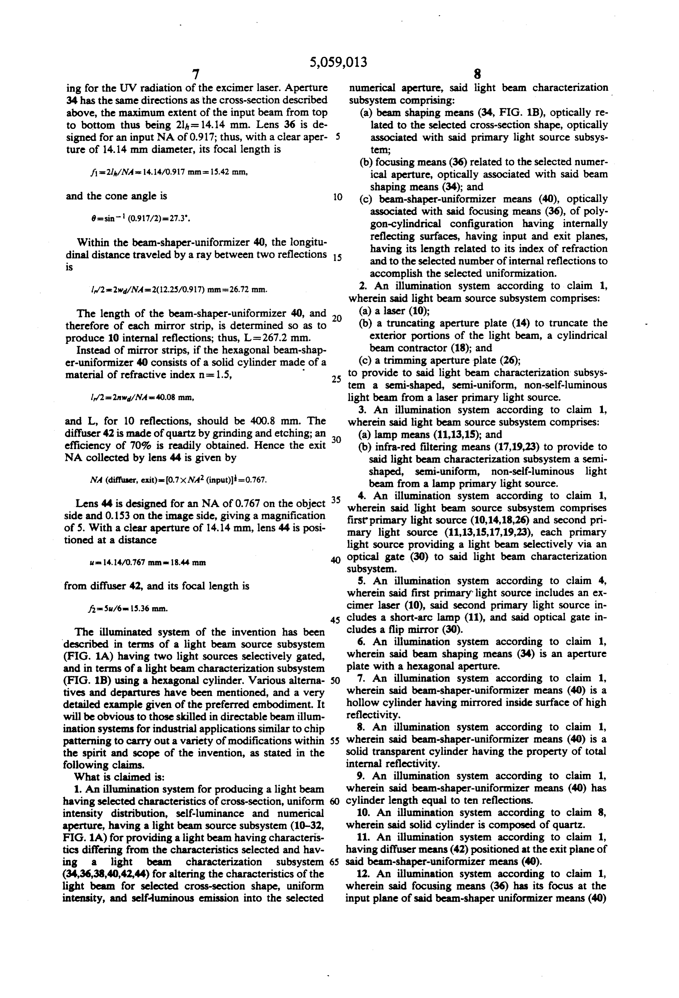
(b) focusing means (36) related to the selected numer f=2l/NAs 14.4/0.917 nm - 5.42 mm, ical aperture, optically associated with said bean shaping means (34); and and the cone angle is O (c) beam-shaper-uniformizer means (40), optically 8=sin(0.917/2)=27.3". associated with said focusing means (36), of poly gon-cylindrical configuration having internally
Within the beam-shaper-uniformizer 40, the longitu reflecting surfaces, having input and exit planes, dinal distance traveled by a ray between two reflections 15 having its length related to its index of refraction is and to the selected number of internal reflections to accomplish the selected uniformization.
l/2s2w/NA=2(12.25/097) mm =26.72 mm. 2. An illumination system according to claim 1, wherein said light bean source subsystem comprises:
The length of the beam-shaper-uniformizer 40, and 20 (a) a laser (10);
therefore of each mirror strip, is determined so as to (b) a truncating aperture plate (14) to truncate the produce 10 internal reflections; thus, L = 267.2 mm. exterior portions of the light beam, a cylindrical Instead of mirror strips, if the hexagonal beam-shap beam contractor (18); and er-uniformizer 40 consists of a solid cylinder made of a (c) a trimming aperture plate (26); material of refractive index n = 1.5, 25 to provide to said light beam characterization subsys tem a semi-shaped, semi-uniform, non-self-luminous l/2=2n w/NAs 40.08 mm, light bean from a laser primary light source. 3. An illumination system according to claim 1, and L, for 10 reflections, should be 400.8 mm. The wherein said light beam source subsystem comprises: diffuser 42 is made of quartz by grinding and etching; an (a) lamp means (11,13,15); and efficiency of 70% is readily obtained. Hence the exit 30 (b) infra-red filtering means (17,19,23) to provide to NA collected by lens 44 is given by said light beam characterization subsystem a semi NA (diffuser, exit)=(0.7x NA2 (input)=0.767. shaped, semi-uniform, non-self-luminous light beam from a lamp primary light source.
Lens 44 is designed for an NA of 0.767 on the object wherein4. An illumination system according to claim 1, side and 0.153 on the image side, giving a magnification first primary said light beam source subsystern comprises light source (10,14,18,26) and second pri of 5. With a clear aperture of 14.14 mm, lens 44 is posi mary light source (11,13,15,17,19,23), each primary tioned at a distance light source providing a light beam selectively via an its 14.4/0.767 mm and 18.44 mm optical gate (30) to said light beam characterization subsystem.
from diffuser 42, and its focal length is 5. An illumination system according to claim 4, wherein said first primary light source includes an ex fe5u/6s 15.36 mm. cimer laser (10), said second primary light source in cludes a short-arc lamp (11), and said optical gate in
The illuminated system of the invention has been cludes a flip mirror (30).
described in terms of a light beam source subsystem 6. An illumination system according to claim 1, (FIG. 1A) having two light sources selectively gated, wherein said bean shaping means (34) is an aperture and in terms of a light beam characterization subsystem plate with a hexagonal aperture.
(FIG. 1B) using a hexagonal cylinder. Various alterna SO 7. An illumination system according to claim 1, tives and departures have been mentioned, and a very wherein said bean-shaper-uniformizer means (40) is a detailed example given of the preferred embodiment. It hollow cylinder having mirrored inside surface of high will be obvious to those skilled in directable beam illum reflectivity.
ination systems for industrial applications similar to chip 8. An illumination system according to claim 1, patterning to carry out a variety of modifications within 55 wherein said beam-shaper-unifornizer means (40) is a the spirit and scope of the invention, as stated in the solid transparent cylinder having the property of total following claims. internal reflectivity.
What is claimed is: 9. An illumination system according to claim 1, 1. An illumination system for producing a light beam wherein said beam-shaper-unifornizer means (40) has having selected characteristics of cross-section, uniform cylinder length equal to ten reflections. intensity distribution, self-luminance and numerical 10. An illumination system according to claim 8, aperture, having a light beam source subsystem (10-32, wherein said solid cylinder is composed of quartz. FIG. 1A) for providing a light beam having characteris 11. An illumination system according to claim 1, tics differing from the characteristics selected and hav having diffuser means (42) positioned at the exit plane of ing a light bean characterization subsystem 65 said beam-shaper-uniformizer means (40).
(34,36,38,40,42,44) for altering the characteristics of the 12. An illumination system according to claim 1, light beam for selected cross-section shape, uniform wherein said focusing means (36) has its focus at the intensity, and self-luminous emission into the selected input plane of said beam-shaper uniformizer means (40)
Page 8
with a focal length selected to produce the selected 17. The apparatus of claim 15 combined with and numerical aperture. preceded by optical means (15) to collect and collimate 13. An illumination system according to claim 12, the light from an extended point source (11,13,); wherein said beam-shaper-uniformizer means (40) is a beam splitter means (17) to transmit ultraviolet radia hollow cylinder having mirrored inside surfaces of high 5 tion and to reflect infra-red and visible radiation in reflectivity, and said focusing means (36) focuses the the light beam; infra-red sink means (19) to absorb beam at the input plane such that input numerical aper the infra-red and visible radiation; ture and exit plane numerical apertures are identical and narrowband filter means (23) to select a spectrally the cone angle (6) at the input plane is narrow linewidth from the ultraviolet radiation;
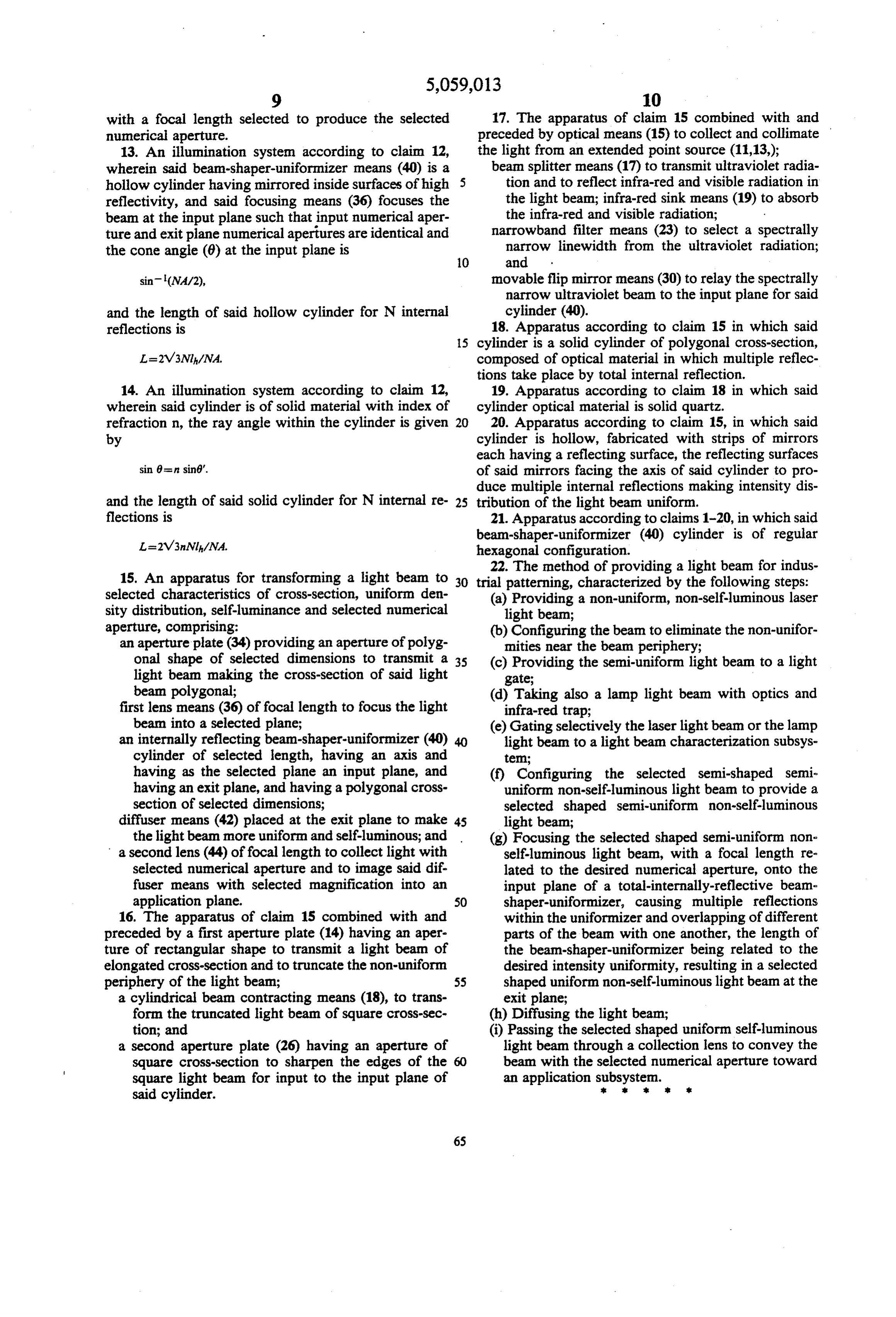
sin(NA/2), movable flip mirror means (30) to relay the spectrally narrow ultraviolet beam to the input plane for said and the length of said hollow cylinder for N internal cylinder (40).
reflections is 18. Apparatus according to claim 15 in which said 15 cylinder is a solid cylinder of polygonal cross-section, composed of optical material in which multiple reflec tions take place by total internal reflection.
14. An illumination system according to claim 12, 19. Apparatus according to claim 18 in which said wherein said cylinder is of solid material with index of cylinder optical material is solid quartz. refraction n, the ray angle within the cylinder is given 20 20. Apparatus according to claim 15, in which said by cylinder is hollow, fabricated with strips of mirrors each having a reflecting surface, the reflecting surfaces sin 8s in sin6. of said mirrors facing the axis of said cylinder to pro duce multiple internal reflections making intensity dis and the length of said solid cylinder for N internal re- 25 tribution of the light beam uniform. flections is 21. Apparatus according to claims 1-20, in which said beam-shaper-uniformizer (40) cylinder is of regular hexagonal configuration.
22. The method of providing a light beam for indus 15. An apparatus for transforming a light beam to 30 trial patterning, characterized by the following steps: selected characteristics of cross-section, uniform den (a) Providing a non-uniform, non-self-luminous laser sity distribution, self-luminance and selected numerical light bean;
aperture, comprising: (b) Configuring the beam to eliminate the non-unifor an aperture plate (34) providing an aperture of polyg mities near the beam periphery; onal shape of selected dimensions to transmit a 35 (c) Providing the semi-uniform light beam to a light light beam making the cross-section of said light gate;
beam polygonal; (d) Taking also a lamp light beam with optics and first lens means (36) of focal length to focus the light infra-red trap;
beam into a selected plane; (e) Gating selectively the laser light beam or the lamp an internally reflecting beam-shaper-uniformizer (40) light beam to a light beam characterization subsys cylinder of selected length, having an axis and tem;
having as the selected plane an input plane, and (f) Configuring the selected semi-shaped semi having an exit plane, and having a polygonal cross uniform non-self-luminous light beam to provide a section of selected dimensions; selected shaped semi-uniform non-self-luminous diffuser means (42) placed at the exit plane to make 45 light beam;
the light beam more uniform and self-luminous; and (g) Focusing the selected shaped semi-uniform non a second lens (44) of focal length to collect light with self-luminous light beam, with a focal length re selected numerical aperture and to image said dif lated to the desired numerical aperture, onto the fuser means with selected magnification into an input plane of a total-internally-reflective beam application plane. 50 shaper-uniformizer, causing multiple reflections 16. The apparatus of claim 15 combined with and within the uniformizer and overlapping of different preceded by a first aperture plate (14) having an aper parts of the beam with one another, the length of ture of rectangular shape to transmit a light beam of the beam-shaper-uniformizer being related to the elongated cross-section and to truncate the non-uniform desired intensity uniformity, resulting in a selected periphery of the light beam; 55 shaped uniform non-self-luminous light beam at the a cylindrical beam contracting means (18), to trans exit plane;
form the truncated light beam of square cross-sec (h) Diffusing the light beam;
tion; and (i) Passing the selected shaped uniform self-luminous a second aperture plate (26) having an aperture of light beam through a collection lens to convey the square cross-section to sharpen the edges of the 60 beam with the selected numerical aperture toward square light beam for input to the input plane of an application subsystem.
said cylinder.
Provenance
- Collection
- Cited prior art
- Original PDF
- patentimages.storage.googleapis.com →
- Filed
- 1988-08-29
- Pages
- 8
- Method
- pdftotext (the PDF's own text layer) + pdftoppm 300dpi page scans
- Source
- Google Patents bibliographic record
- Granted
- 1991-10-22
- Inventors
- Kantilal Jain
- Transcribed from
- patentimages.storage.googleapis.com →