patent · US5381309
Backlit display with enhanced viewing properties
10 January 1995
Page 1 — bibliographic record
United States Patent 19 11 Patent Number: 5,381,309 Borchardt 45 Date of Patent: Jan. 10, 1995 54 BACKLIT DISPLAY WITH ENHANCED 3M/Optical Systems, "Right Angle Backlighting Tech VIEWTNG PROPERTIES nology Design Aid', 15 pages.
"Brightness Enhancement Film', 10 pages.
(75) Inventor: Jerry
Minn.
L. Borchardt, Maple Grove, "EE";650.663, Brightness
Enhancement Film (BEF)', 2 pages (1993).
73 Assignee: Honeywell Inc, Minneapolis, Minn. 3M, "Diffusion Film”, 6 pages. 3M product brochure 75-0500-0563-8, “Light Diffus 21) Appl. No.: 130,084 ing Film', 2 pages (1993). 22 Filed: Sep. 30, 1993 Primary Examiner-Ira S. Lazarus 5ll Int. Cl............................................... F21v 13/00 Assistant Examiner-Thomas M. Sember 52 U.S.C. ........................................ 362/31362/26. Attorney, Agent, or Firm-Charles L. Rubow 362/27; 362/30,362/331 57 ABSTRACT
362 362/800, 26, 30, 27, A high aspect ratio, backlit liquid crystal display in 62/31, 331, 332, 333; 40/546 which light from opposing rows of light emitting diodes 56) References Cited is projected into the ends of a thin optical cavity. The
the interior surface is specularly reflective and an op
E. 6, t m 362/27 posing major wall including a layer of transparent mate 452238 5/1556 E. p 362/31 rial having an interior surface formed with an array of 4,984.14 1/155i coal." regularly spaced, fine, triangular prisms which tend to 4,994,941 2/1991 Wen ...................................... 3626 collimate light received from the cavity and project it 5,054,885 10/1991 Melby. outwardly perpendicular to the major wall. A diffusion 5,070,431 12/1991 Kitazawa et al. ................ 362/26 X layer overlays the layer of transparent material, and a 5,190,370 3/1993 Miller et al. . brightness enhancing film overlays the diffusion layer 5,272,601 12/1993 McKillip ............................... 362/27 and functions to convert diffuse illumination received OTHER PUBLICATIONS through the diffusion layer into directed illumination predominantly falling within the a viewing space
R. McCartney, et al., “S7-7 Directional Diffuser Lens bounded by predetermined angles. Array for Backlit LCD's', Japan Display '92, pp.
259-262. 10 Claims, 4 Drawing Sheets
17 18 12 2O
SyWAYZZZZZZ
Stift
MKSSSSSSSSS a" A.
2 RNff
SVY
IZZZZZZZZZZZZZZZZZZZ
Page 2
Drawing sheet — no readable text.
Page 3
Drawing sheet — no readable text.
Page 4
Drawing sheet — no readable text.
Page 5
Drawing sheet — no readable text.
Page 6
and have modest energization circuitry requirements.
BACKLIT DISPLAY WITHENHANCED VIEWING However, such diodes are essentially point light sources PROPERTIES which, if used to backlight a relatively large area, must BACKGROUND OF INVENTION be combined with other optical elements for evenly 5 distributing and directing the light output.
The invention disclosed herein relates generally to A variety of multifaceted lens products are now backlighting for display panels which are at least par available for achieving a large aperture with a thin tially translucent, and to corresponding illuminated element. One such family of products includes transmis display devices of the type incorporating backlighting from a high aspect ratio illumination source. More par O sive and reflective optical films available through Min ticularly the invention relates to such a display device scribed Mining nesota
and Manufacturing Company, and de
and illumination source employing light emitting diodes 5,054,885 and 5,190,370. These films are characterized in conjunction with an optical cavity and enhancement films to provide improved viewability from a relatively by a major surface formed with an array regularly wide range of viewing angles. 15 spaced, parallel, fine, triangular prisms which serve to There are various situations in which it is desired or redirect light received from a range of angles to a rela necessary that information be displayed so as to be read tively uniform direction normal to the nominal plane of able under a wide range of ambient light conditions and the film. This characteristic can be utilized to imple throughout a relatively wide range of viewing angles. ment a thin, large aperture light source by projecting In many of these situations it is also highly desirable, if 20 light produced by one or more point sources onto the not required, that the display apparatus be capable of film at a very small angle relative to the nominal plane automatic updating of the displayed information and/or of the film.
permitting selection of the information to be displayed. One of the more difficult design problems with such Another characteristic which is desired and often im a light portant is that the apparatus be robust and require mini rangement 25 source implementation is the selection and ar mum maintenance. of materials which will achieve illumination A specific application requiring such a display device of uniform intensity and direction over the entire aper relates to monitoring the status and/or operation of ture. Uniform intensity and direction of illumination is environmental control equipment on mobile shipping required to avoid "hot spots”, voids, streaks, an inade containers for perishable goods. Such containers, which 30 quate range of angles for acceptable viewing and other each have a refrigeration unit and/or other environ defects.
mental control apparatus, may, during a single trip, be The applicant has discovered a unique combination moved by train, track and/or marine vessel, and moved and arrangement of optical elements which provides for from one mode of transportation to another by crane or enhanced viewing of a display backlit with a thin, large other cargo handling equipment. During the shipping 35 aperture light source, thereby avoiding many of the process, it may be necessary to periodically check on disadvantages of prior known display devices. operation of the refrigeration or other environmental control equipment and the status of environmental con SUMMARY OF THE INVENTION ditions within the container. A display device for pres The invention is a backlit display device and thin, enting this information is typically installed at a conve 40 large aperture light source for such a display device, the nient location on each container. Since it may be neces light source including an optical cavity bounded in part sary to perform a status check at any time of the day or night and under varying climatic conditions, the display by a pair of opposing major walls, the, first major wall must be illuminated so as to be easily readable during having a specularly reflective interior surface and the daylight as well as dark conditions. Further, since the 45 second major wall including an interior layer or film of containers may be stacked as many as three high, and on transparent material whose interior surface is config platforms such as a truck or rail car bed, it may be ured with an array of regularly spaced triangular prisms necessary to read the display from a variety of viewing extending across the optical cavity substantially parallel angles ranging between substantially above to some with the ends thereof. The second wall also includes a what below horizontal, and within areasonable range of 50 diffuser which overlays the interior layer and a bright horizontal viewing angles. ness enhancing film which overlays the diffuser, the The requirements for long life, robustness and mini brightness enhancing film being adapted to convert mum maintenance essentially dictate solid state design diffuse illumination into directed illumination falling and construction. Thinness or high aspect ratio of the predominantly within the desired viewing space. Fi display apparatus is also an important consideration in 55 many applications, such as the previously described nally, a planar, at least partially translucent message carrying member overlays the brightness enhancing shipping container environmental control and status film.
monitoring system.
A light source is positioned to project light into the
Although several flat panel technologies are available optical for producing illumination, such technologies including cavity from at least one end thereof. The light solid state florescent and electroluminescent devices, source may be formed of first and second opposing light sources based on these technologies have various rows of light emitting diodes at opposite ends of the disadvantages, such as high initial cost, excessive degra optical cavity, the light emitting diodes each being dation of light output with time, limited useful life and adapted and oriented to produce a light beam whose /or requirements for complex driver or energization 65 center line intersects the interior surface of the first circuitry. major wall at a point substantially 40 percent of the Light emitting diodes which produce a relatively length of the optical cavity from the end at which the highlight output are readily available, and inexpensive, diode is located.
Page 7
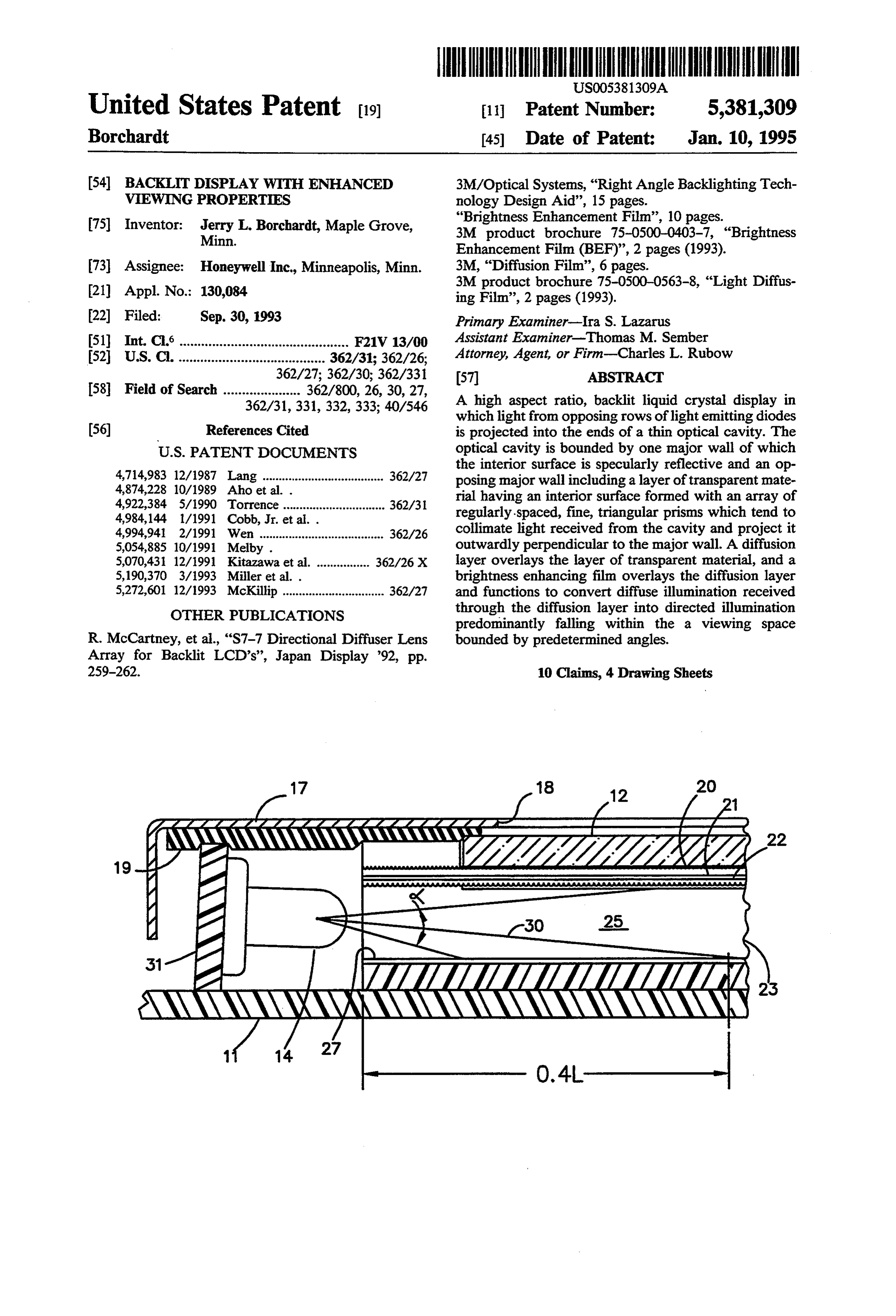
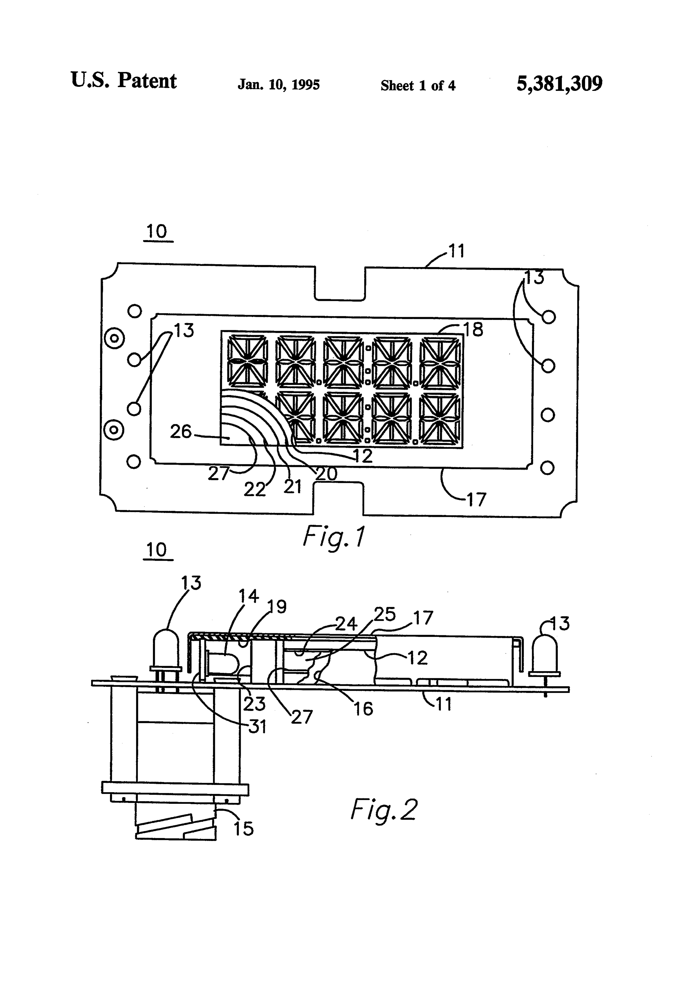
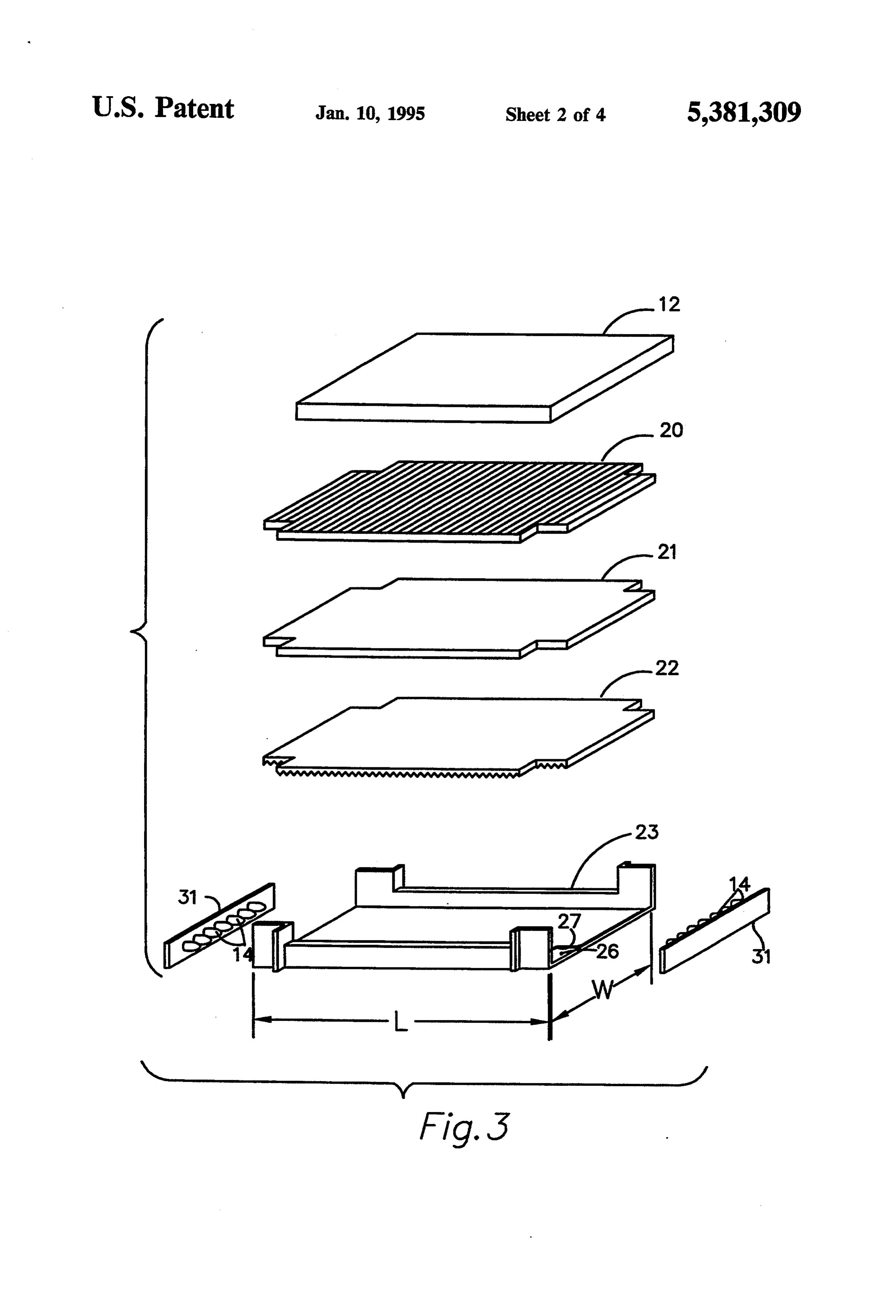
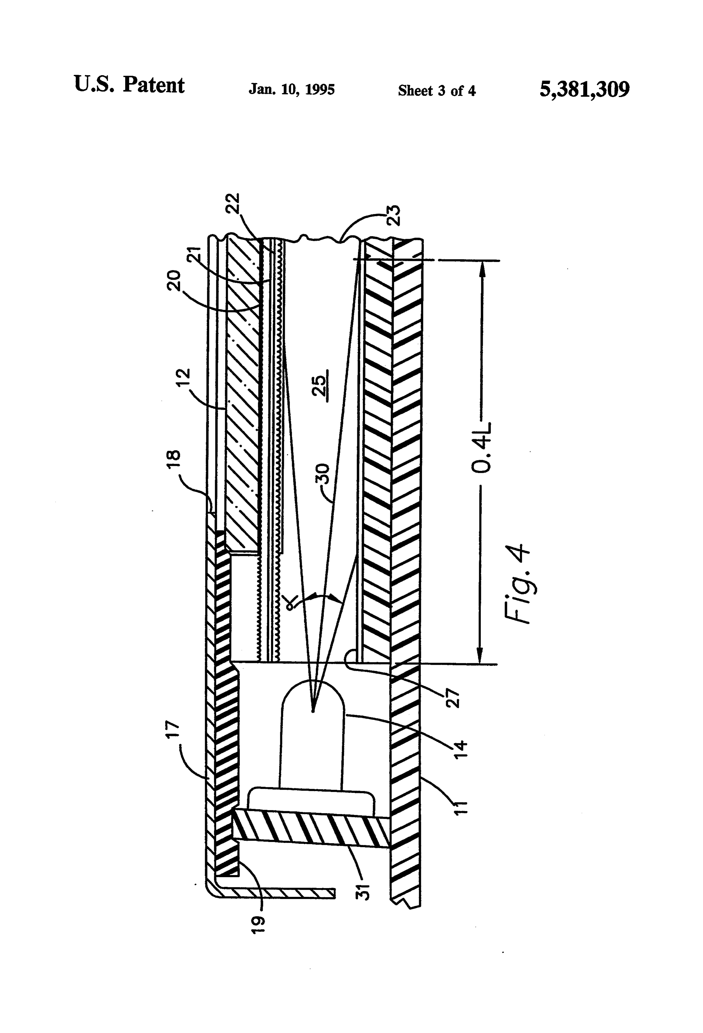
BRIEF DESCRIPTION OF THE DRAWINGS light beam along a center line identified by reference numeral 30 in FIG. 4. The light beam predominantly
FIG. 1 is a frontal view of a display device in accor falls within a cone having an apical angle a of nominally dance with the applicant's invention, partially broken 15 degrees for the diodes selected for this application. a. away to show internal optical layers; represents the angle at which light output from diodes FIG. 2 is an edge view of the display device of FIG. 14 drops to one half of its intensity on center line 30. 1, partially in section and partially broken away; It has been found that best performance of display FIG. 3 is an exploded perspective view in simplified device 10, in terms of intensity and evenness of light form of the principal optical elements in the display distribution, is achieved by orienting light emitting di device of FIGS. 1 and 2; O odes 14 so that their beam center lines 30 each intersect FIG. 4 is an enlarged partial cross sectional view of specular surface 27 at a point 40 percent of the length L the display device of FIGS. 1 and 2, showing its internal of cavity 25 from the end at which the diode is located. geometry; and This is accomplished by mounting diodes 14 on a pair of FIG. 5 is a much enlarged schematic representation daughter boards 31 which are mounted on circuitboard in exploded form of certain optical layers in the display 15 11 at a slight angle from perpendicular to the board. device of FIGS. 1 and 2, illustrating light processing As is apparent from the above described geometry, within the device. and is most clearly illustrated in FIG. 4, light is trans DESCRIPTION OF THE PREFERRED mitted to the inner surface of transmissive right angle EMBODIMENT film 22, which is the inner element of the lens assembly 20 forming major wall 24 of the optical cavity structure,
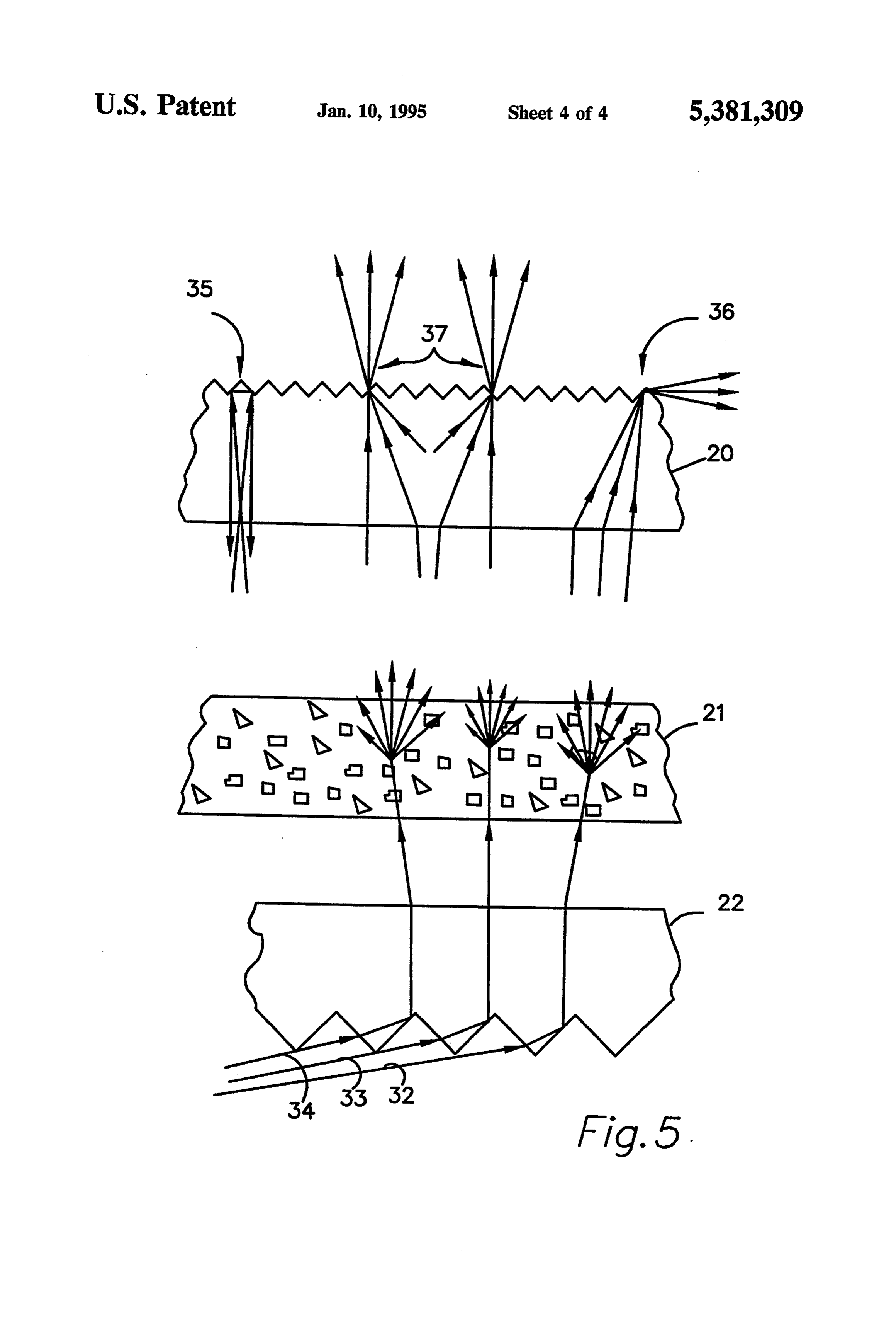
In FIGS. 1 and 2, reference numeral 10 generally both directly from diodes 14 and indirectly from the identifies a display device in accordance with the appli diodes by means of reflection from specular surface 27. cant's invention. The invention pertains primarily to A general understanding of the light distribution char optical elements which, in the embodiment shown in acteristics of the lens assembly can be obtained from FIGS. 1 and 2, are assembled on a printed circuit board 25 FIG. 5 which illustrates the paths taken by representa 11. Circuitboard 11 in addition to providing astructural tive light rays.
base for the optical elements, carries electronic circuitry for selectively energizing segments of a liquid crystal areItnot is pointed out that the features illustrated in FIG. 5 to scale. In addition, the adjacent surfaces of display panel 12 and other indicator lamps, such as films 20, 21 and 22 are preferably contiguous. The those identified by reference numeral 13, in addition to 30 spaces in FIG. 5 between the films are provided only to supplying electric power to backlighting lamps 14, as facilitate a general description of the optical character will be further described hereinafter, in response to istics. Reference may be made to available product signals received through an interface connector 15. literature on brightness enhancing film 20, diffusion film Display panel 12 is electrically connected to circuit 21 and transmissive right angle film 22 for more detailed board 11 through edge connectors, of which one is 35 information on these products.
identified by reference numeral 16 in FIG. 2. As shown in FIGS. 4 and 5, the angle at which the Liquid crystal display panel 12 is one of several pla predominant light rays arrive at the faceted surface of nar optical elements or layers sandwiched together and film 22 are within a few degrees from horizontal. The held in place between printed circuit board 11 and a most horizontal rays travel directly from diode 14 to the bezel or cover 17 having an aperture 18 through which 40 end offilm 22 most remote from the diodes which emit the display surface of liquid crystal display panel 12 can ted the rays. The rays which arrive at the greatest angle be viewed. Reference numeral 19 identifies a gasket from horizontal are those reflected from the end of between display panel 12 and cover 17. specular surface 27 nearest the emitting diodes. Refer Beneath liquid crystal display panel 12 are several ence numerals 32, 33 and 34 identify rays within this optical layers, including a brightness enhancing film 20, 45 range at progressively greater angles from horizontal. a diffuser 21 and a transmissive right angle film 22, As illustrated in FIG. 5, rays 32, 33 and 34 are subject whose functions will be described in greater detail here to total internal reflection from the facets on the inner inafter. These elements are mounted on the open face of surface of film 22, and are redirected at approximately a shallow. open ended trough 23 which can be better 90 from the original direction. Thus, the rays emerge visualized from examination of the exploded perspec 50 from the surface of film 22 opposite the faceted surface tive view FIG. 3. Elements 20-22 form a lens assembly thereof throughout a small range of angles from perpen which provides one major wall (identified by reference dicular to the plane of the film.
numeral 24 in FIG. 2) of an optical cavity structure Light transmitted through film 22 is then dispersed defining a high aspect ratio optical cavity 25 having a over a wide range of directions by diffusion film 21 to length L and a width W, as shown in FIG. 3. 55 achieve evenly distributed illumination. The light trans A second major wall 26 of the optical cavity struc mitted through diffusion film 21 is then supplied to ture is formed by a bottom wall of trough 23. At least brightness enhancing film 20 which functions to redi web 26 is provided with a specularly reflective interior rect a majority of the light to directions within angles surface 27, which may be in the form of a highly reflec bounding a desired viewing space. In particular, light tive film applied to the surface. A reflective polyester transmitted to brightness enhancing film 20 internally is film product designated as Silverlux available through treated in one of three ways depending on the angle at Minnesota Mining and Manufacturing Company has which light rays enter the film.
been found suitable for this application. As shown at reference numeral 35, light rays ap Backlighting illumination is provided by two rows of proaching film 20 at angles close to perpendicular to the light emitting diodes 14 at the opposite ends of the 65 film undergo double internal reflection from the facets optical cavity structure. The rows extend across the on an outer faceted surface of the film, and returned to width of optical cavity 25. Each light emitting diode 14 diffuser film 21 to be diffusely recycled. Light rays is essentially a point source of light which projects a entering film 20 within a small range of angles slightly
Page 8
less than the angles which result in double internal re ular prisms on the inner layer at a small angle rela flection undergo reflection and refraction, and emerge tive to an interior surface of the second major wall. from the faceted surface of the film in approximately 2. The display device of claim 1 wherein said light horizontal directions, as shown at reference numeral 36. source is adapted and oriented to produce a light beam These rays represent a small amount of lost light. A whose center line intersects the interior surface of the majority of the light rays enter film 20 throughout a second major wall at a point substantially 40 percent of relatively broad range of angles less than the angles of the length of the optical cavity from the end thereof at rays at 35 and 36, and represent illumination useful for which said light source is located. backlighting display panel 12. Such rays are shown at 3. The display device of claim 2 wherein said light reference numeral 37. As illustrated, the rays entering 10 source comprises first and second pluralities of light film 20 within this range of angles are refracted by the emitting diodes located at first and second opposing faceted surface of the film, and emerge from the faceted ends of the cavity respectively.
surface distributed throughout a range of angles cover 4. The display device of claim 3 wherein the first and ing the desired viewing space for the display. second pluralities of light emitting diodes each comprise The applicant has discovered that the particular com 15 a linear array of light emitting diodes substantially par bination of elements and geometry described above Structure. allel to the first and second major walls of the optical results in a display device having significantly enhanced viewing properties. In particular, this arrangement max 5. The display device of claim 4 wherein each of the imizes the amount of illumination produced by the light 20 diodes in the first and second pluralities of light emitting source which is effectively used to backlight the display diodes produce a light beam having a half peak intensity panel. This illumination is evenly distributed, thereby aperture of substantially 15.
avoiding voids, "hot spots', streaking and other unde carrying 6. The display device claim 5 wherein said message sirable characteristics. It also directs a maximum member is a liquid crystal display panel which amount of the illumination to within angles bounding 25 of is translucent when unenergized, and having a plurality the desired viewing space, resulting in uniform readabil come selectively energizable display segments which be ity throughout a desired extended range of angles. substantially opaque when energized. Accordingly, the applicant has provided a high as 7. The display device of claim 6 wherein said optical structure is mounted on a printed circuit board with the pect ratio, backlit display device having superior view second ing characteristics. A particular embodiment is shown adjacentmajor wall of said optical cavity structure being printed circuit board, said optical structure and described for illustrative purposes. However it is 30 being not intended that coverage be limited to that embodi diodeslocated carried between opposing rows of light emitting on said printed circuitboard and forming ment, but only by the terms of the following claims. said light source, said printed circuit board also carry The embodiments of the invention in which an exclu ing electronic circuitry for selectively energizing the sive property or right is claimed are defined as follows: 35 display segments of said liquid crystal display panel. 1. A high aspect ratio, backlit display device with 8. A high aspect ratio illumination source for back enhanced viewing properties, comprising: lighting a planar, at least partially translucent, display a message carrying member having a display surface surface with directed illumination predominantly falling of predetermined length and width of which at within a viewing least a portion is translucent, said message carrying gles relative to thespace bounded by predetermined an display surface, the display surface member having a first side from which the message having a predetermined length and width, the light is to be readable within a viewing space bounded source comprising:
by predetermined angles relative to the first side, an optical cavity structure defining an optical cavity said message carrying member having a second having opposite ends, and having a length and side opposite the first side; 45 width at least equal to the predetermined length an optical structure having first and second generally and width of the display surface, said optical cavity parallel major walls at least partially enclosing a structure having a first major wall with an interior thin cavity having a length and width at least as surface adapted to provide specular reflection and great as the predetermined length and width of the a second major wall including an interior layer of display surface, the cavity having a first end sub 50 transparent material, the interior layer of transpar stantially parallel with the width of the cavity and ent material having an interior surface configured transverse to the first and second major walls with an array of regularly spaced triangular prisms thereof, the first major wall of said optical struc extending across the optical cavity substantially ture including an inner layer of transparent mate parallel with the ends thereof; rial having an interior surface bounding the cavity, 55 a light source adapted to project light into the optical an intermediate optical diffusion layer and an outer cavity from at least one end thereof; brightness enhancing film layer having an inner a diffusion layer overlaying the exterior surface the surface adjacent the diffusion layer and an outer interior layer of transparent material in the second surface adjacent the display surface, the interior major wall of said optical cavity structure; and surface of the inner layer and the outer surface of 60 a brightness enhancing film overlaying said diffusion the outer layer each being configured with an array layer, said brightness enhancing film having a first of regularly spaced triangular prisms parallel with surface adjacent said diffusion layer and a second the width of the cavity, the second major wall of opposing surface configured with an array of regu said optical structure being adapted to provide larly spaced triangular prisms parallel with the specular reflection; and 65 triangular prisms formed in the interior layer of the a light source adapted to project light from the end of second major wall of said optical cavity structure, the cavity onto the second major wall of said opti the prisms on said brightness enhancing film having cal structure in a direction transverse to the triang faces whose included angles and angular orienta
Page 9
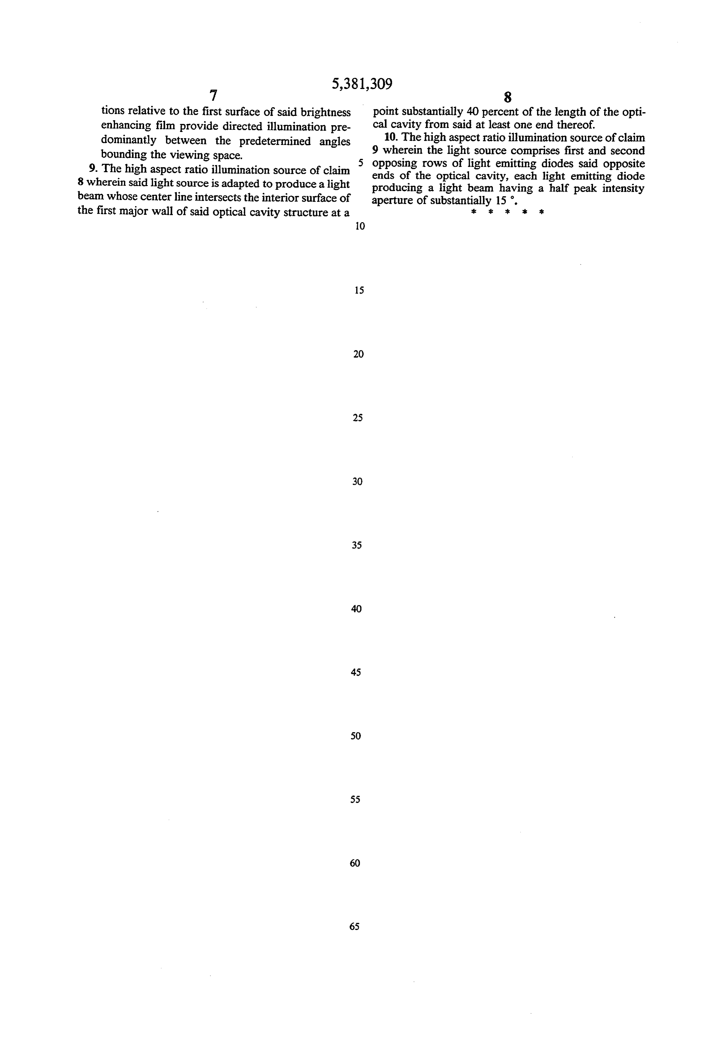
tions relative to the first surface of said brightness point substantially 40 percent of the length of the opti enhancing film provide directed illumination pre cal cavity from said at least one end thereof. dominantly between the predetermined angles 10. The high aspect ratio illumination source of claim bounding the viewing space. 9 wherein the light source comprises first and second 9. The high aspect ratio illumination source of claim opposing rows of light emitting diodes said opposite 8 wherein said light source is adapted to produce a light ends of the optical cavity, each light emitting diode producing a light beam having a half peak intensity beam whose center line intersects the interior surface of aperture of substantially 15. the first major wall of said optical cavity structure at a : : sk it st
Page 10
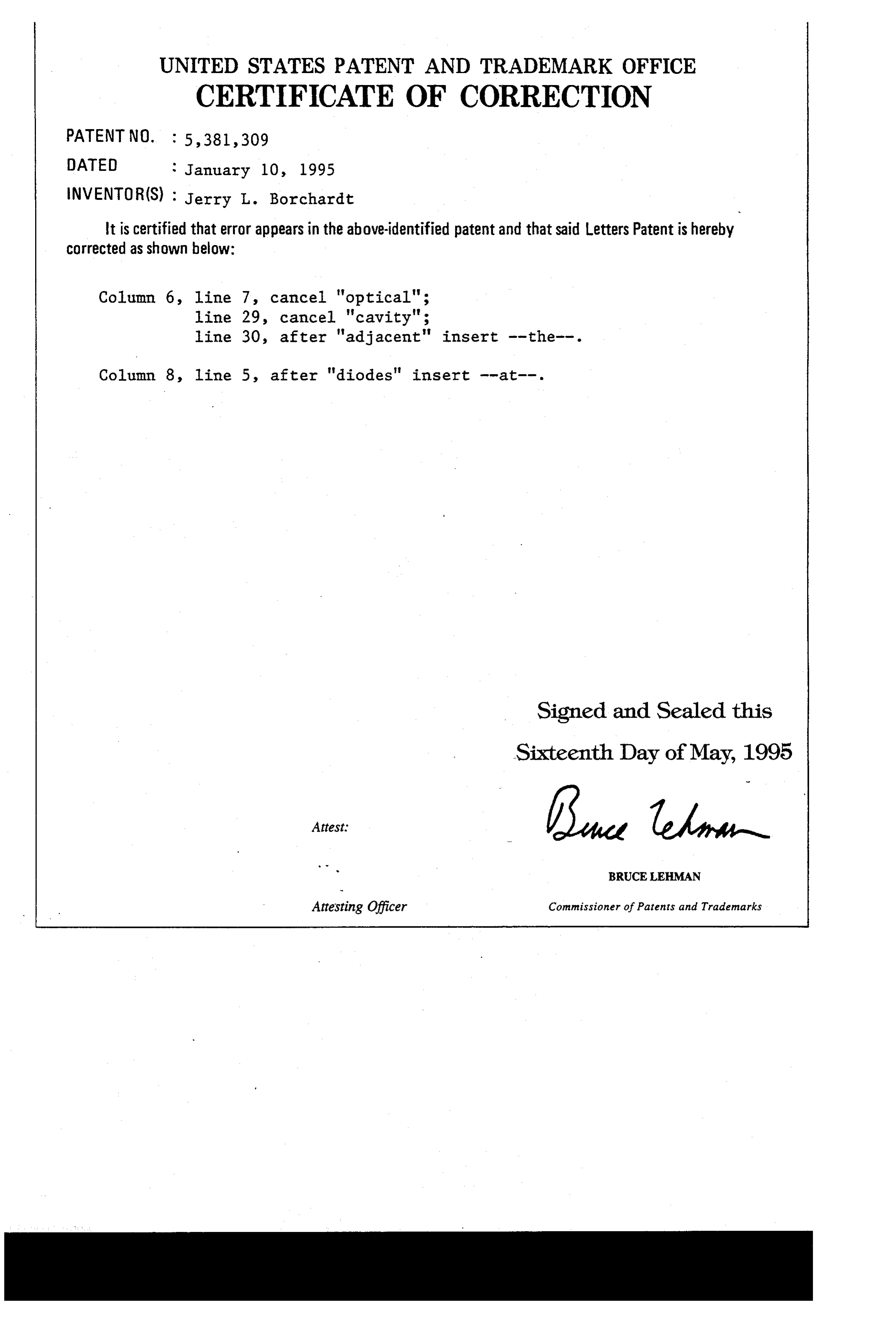
UNITED STATES PATENT AND TRADEMARK OFFICE
CERTIFICATE OF CORRECTION
INVENTOR(S) : Jerry L. Borchardt
It is certified that error appears in the above-identified patent and that said Letters Patent is hereby Corrected as shown below:
Column 6, line 7, cancel 'optical";
line 29, cancel 'cavity";
line 30, after "adjacent' insert --the--. Column 8, line 5, after "diodes' insert --at--.
Signed and Sealed this
Sixteenth Day of May, 1995
BRUCE LEEMAN
Attesting Officer Commissioner of Patents and Trademarks
Provenance
- Collection
- Cited prior art
- Original PDF
- patentimages.storage.googleapis.com →
- Filed
- 1993-09-30
- Pages
- 10
- Method
- pdftotext (the PDF's own text layer) + pdftoppm 300dpi page scans
- Source
- Google Patents bibliographic record
- Granted
- 1995-01-10
- Inventors
- Jerry L. Borchardt; Honeywell Inc
- Transcribed from
- patentimages.storage.googleapis.com →