patent · US3425056
Warning lens having concentric lenticular elements
28 January 1969
Page 1
Drawing sheet — no readable text.
Page 2
Drawing sheet — no readable text.
Page 3
Drawing sheet — no readable text.
Page 4
United States Patent Office 3,425,056 Patented Jan. 28, 1969
3,425,056 10 in circular and has parallel curve front and rear base
WARNING LENS HAVING CONCENTRIC Surfaces 11 and 12, arcuate in cross section. The central LENTICULAR ELEMENTS portion 13 of the lens is of the fresnel type for focusing Robert E. Dawson, Huntingdon Valley, Pa., assignor to and distributing light from a light source, centered at S on R. E. Dietz Company, Syracuse, N.Y. the lens axis 14, divergently to the area in front of the Filed Nov. 27, 1964, Ser. No. 414,103 lens. The outer annular flange or rim portion 15 is pro U.S. C. 340-383 6 Claims vided with reflex reflector means, not shown, as is usual Int. C. G09f 13/04 in warning lenses.
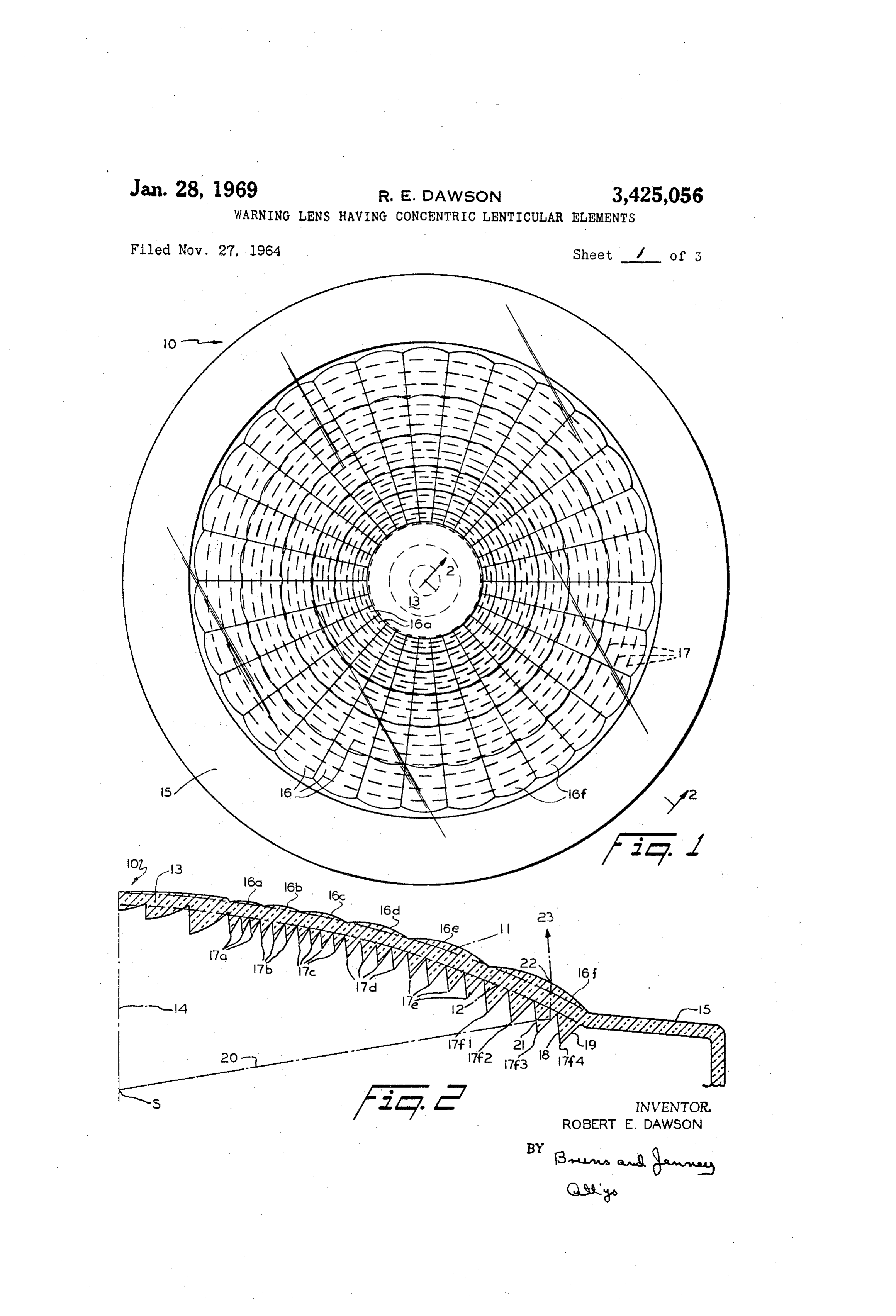
Between the central portion 13 and rim 15 the front 0 base surface 11 is provided with projecting light-emitting
ABSTRACT OF THE DISCLOSURE spherically-surfaced lenticular elements 16. The elements A dished warning lens having spherically surfaced len 16 are arranged in successive circular rows or annular ticular elements projecting from the arcuate front base bands of elements 16a, 16b, 16c, 1.6d, 16e and 16f, respec surface and V-shaped catadioptric rings projecting from tively. The surfaces of the elements are of successively the rear base surface. The elements are contiguous and 15 larger spherical radius from the row 16a adjacent the lens arranged in successive annular bands, the successive ele center portion to the row 16f adjacent the reflective rim ments of the bands being arranged radially of the lens. 15. The separate elements 16 of the circular rows of ele The rings are concentric and there are a plurality of rings ments 16 are divided along equiangularly spaced radii or opposite each band of elements, the reflective surface of 20 lines from the lens center, as shown, to form an arrange each ring being disposed at a different selected angle for ment in a radial and circular grid pattern. distributing the light from each band across the conical To those skilled in the art, it will be apparent that the lens beam. straight sides and the curved ends of the surfaces of len ticular elements 16 result from the intersection of spher
This invention relates to lenses and more particularly to 25 ical recesses formed in the mold cavity, the centers of the recesses being disposed along radial lines and the recesses warning or signalling lenses.
The principal object of the invention is to provide a of Alarger spherical radii being of greater depth. plurality of catadioptric rings or annular teeth 17 are warning or signalling lens which projects a highly luminous formed on the rear base surface 12 of the lens 10, by the beam from a comparatively low intensity light source, the beam being of conical configuration about the lens axis 30 usual method of providing the male portion of the mold with tubular elements having angularly related annular and of substantially uniform intensity across the beam. end surfaces as described in Patent 2,831,394 to Heenan Another important object is to provide a lens for con et al., dated April 22, 1958.
verting a beam of large spherical angle into a compara The catadioptric rings 17 are grouped opposite the cir tively narrow beam which, at any given distance, has a cular rows or annular bands of lenticular elements 16, light intensity near the side of the beam closely approach rings 17a being opposite elements 16a, rings 17b being ing that at the center of the beam.
A further object is to provide a warning lens having opposite elements 16b, etc. It will be understood that each ring 17 has a light receiving and refracting surface 18 and lenticular elements of spherical surface-configuration at a total light reflecting surface 19, as indicated with respect the front of the lens and catadioptric rings at the rear of to the ring 17 fa in FIGURE 2, for reflecting a ray of light the lens, the latter being so arranged as to direct light rays 40 from the source toward the lenticular element 16 opposite through the lens body to the lenticular elements to form the respective apparent glowing spots on each element when viewed from at S strikes thering. For example, a ray 20 from the source any point within a predetermined area in front of the lens. 21 and is refracted toward surface refracting 18 of the ring 17f3 at
Other objects and advantages will be apparent from the ring and is then reflected the reflecting surface 19 of the following description in conjunction with the accompany 45 16f opposite the ring, as toward the lenticular element indicated in broken lines in ing drawing in which: FIGURE 2. At the surface of the element 16f, the ray FIGURE 1 is a front elevational view of a lens accord is again refracted at 22, and, as it emerges from the front ing to the invention; surface of the lens, is thereby given a direction as indi FIGURE 2 is sectional view on the line 2-2 of FIG cated by the arrow at 23.
URE 1;
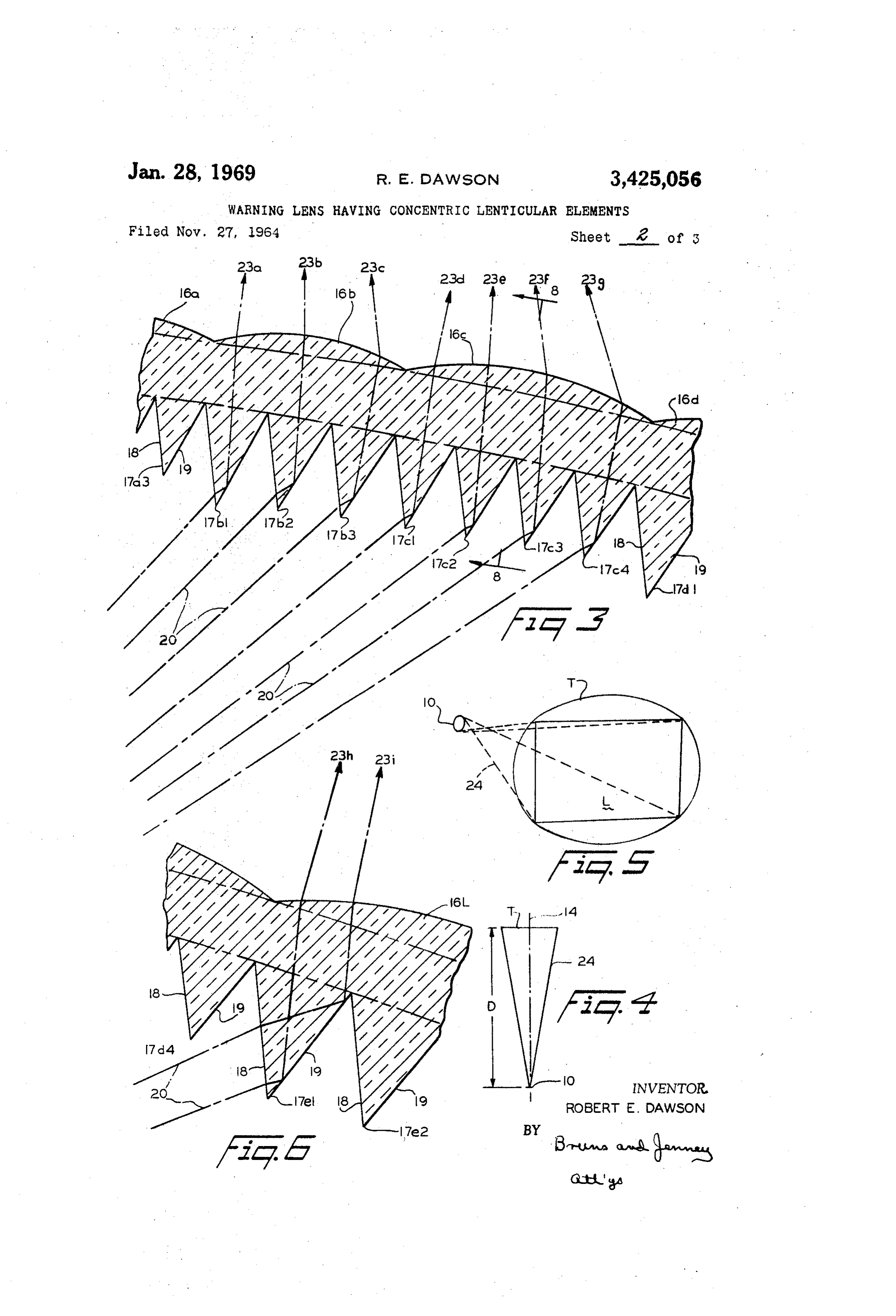
FIGURE 3 is a greatly enlarged sectional view, similar 50 andReferring
now to FIGURE 3, the rings 17b1, 17b2 shown, greatly enlarged, opposite a lenticu to FIGURE 2, showing two adjacent lenticular elements lar elment 16b and rings 17c1, 17c2, 17c3 and 17c4 are and their associated catadioptric rings; shown opposite an element 16c. Rays 20, in the plane of FIGURE 4 is a diagrammatic plan view of a conical the paper, are shown in broken lines coming from a beam cast by the lens; 55 source at S, not shown, striking the refracting surfaces FIGURE 5 is a diagrammatic perspective view of a lens 18 of the respective rings 17, being reflected by the sur and a testing area at a selected distance therefrom; faces 19 of the rings, being again refracted upon emerg FIGURE 6 is an enlarged sectional view similar to FIG ing from the front surface of the lenticular elements 16 URE 3, showing the dispersion of light rays along a and thereby given directions indicated by the arrows 23a, single catadioptric reflecting surface;
FIGURE 7 is a diagrammatic elevational view of the 60 23b, 23c, 23d, 23e, 23f, and 23g.
Each of the surfaces 18 is disposed at the same small testing area of FIGURE 5; angle to the axis of lens 10 for convenience in calculating FIGURE 8 is a sectional view on the line 8-8 of FIG
URE 3; the optics of the lens. The reflecting surfaces 19 of the FIGURES 9 and 10 are enlarged elevational views of rings, however, are given different, carefully calculated an single lenticular elements at the top and one side, respec 65 rection gles with respect to the lens axis for controlling the di of the light emerging from the front surface of tively, of FIGURE 1;
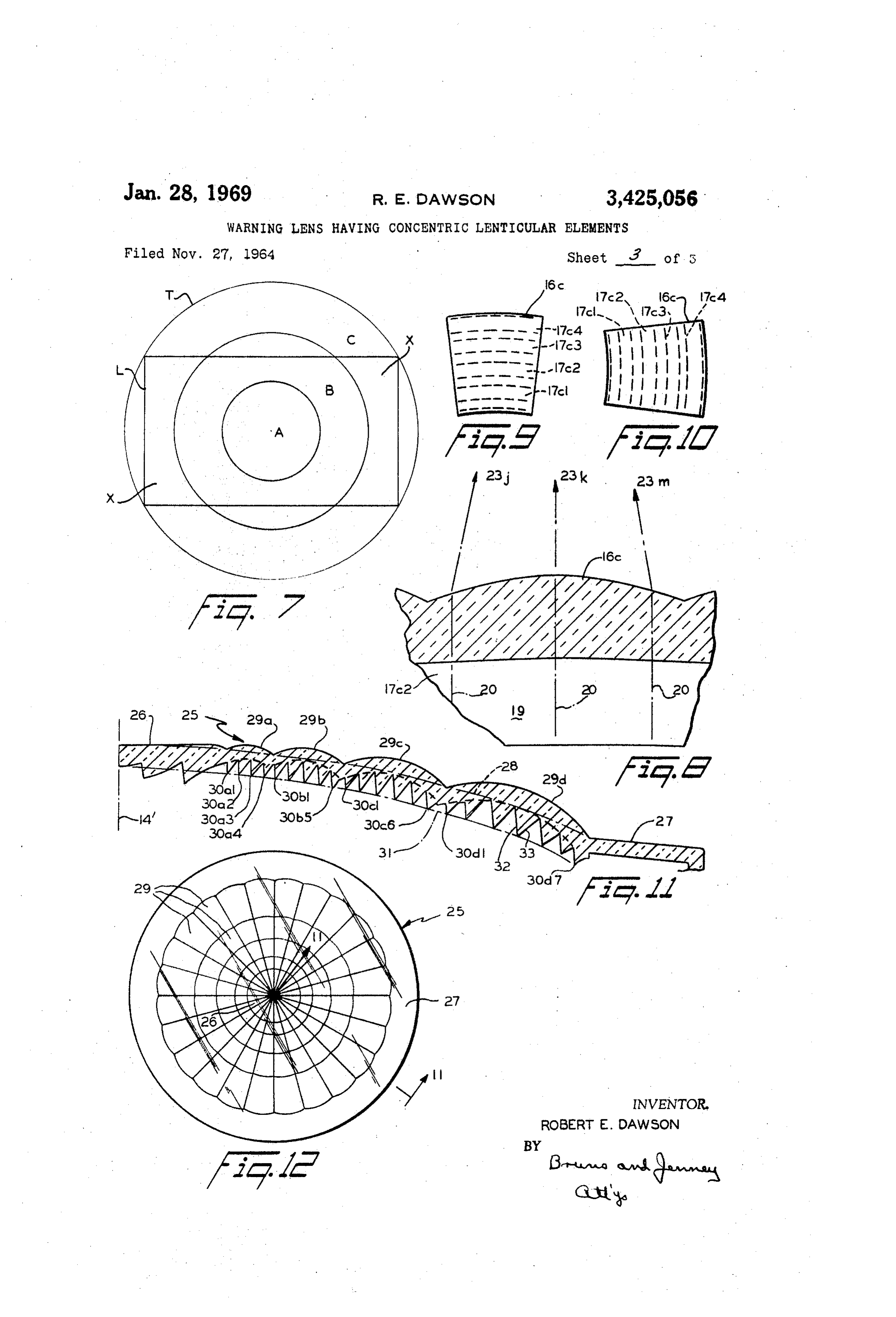
FIGURE 11 is an enlarged sectional view on the line the lens. The rings 17 are selectively disposed in groups 11-11 of FIGURE 12; and opposite the bands of lenticular elements 16 so that light FIGURE 12 is front elevational view of a modified 70 rays received by the refracting surfaces 18 of the rings form of lens according to the invention. are reflected by the reflecting surfaces 19 toward an ele Referring more particularly to FIGURES 1 and 2, lens ment 16 of the opposite band for emergence therefrom.
Page 5
The reflecting surface of each ring in each group is given zone of the target T. The angular disposition of the sur a different angle so as to disperse the emerging light over face 19 of ring 17b2 is computed to direct the emerg a carefully calculated angular area in front of the lens. ing light illustrated by arrow 23b at another zone, and Light received by rings 17b1, 17b2, and 17b3, for exam the surface 19 of ring 17b3 is computed to direct the ple, emerges along the arrows 23a, 23b and 23c, and emerging light along arrow 23c at still another zone. light received by rings 17c1-17c4, inclusive, emerges in Since the rings 17b1, 17b2 and 17b3 are opposite a the directions indicated at 23d-23g, inclusive. The light cooperating group or circular row of elements 16b, it is along 23d and 23g, for example, converges at some point not necessary, in considering light intensity, to consider in front of the lens and crosses, forming a diverging the actual zone on which the light along arrow 23a from beam of light having a definite angular spread and direc 10 any particular element is directed, but only the radial ex tion according to the selected angles at which the reflect tent of this zone, since similar and overlapping zones ing surfaces 19 are disposed, and also according to the are illuminated by other elements 16b in the circular radius of curvature of the surfaces of elements 16 and row. The circular row of elements 16b and the cooperat the index of refraction of the material used in molding ing rings 17b1, 17b2 and 17b3 may, therefore, be re the lens. 5 garded as a complete lens system in the computation of While the rays 20, indicated in FIGURES 2 and 3, are the angular disposition of the surfaces 19 and the light all in the plane of the paper, the rings 17 are annular reflected from each reflecting surface 19 may, in this and the lenticular elements 16 are disposed in cooperat sense, be regarded as collimated light. ing circular rows and all the elements in each row have Referring to FIGURE 7, a circular target area T is the same angular relation to the lens axis and hence the 20 shown divided into a circular central area A, and suc same relation with the reflecting surfaces of the rings cessive annular areas B and C. Light emitted in the di opposite each element. By a careful selection of the angu rection of the arrow 23b of FIGURE 3 falls mainly on lar disposition of the reflecting surfaces of the rings that the zone A, light along the arrow 23a on Zone B and cooperate with each circular row of elements, therefore, light along arrow 23c on zone C. There is an overlapping the distribution of light as it emerges from all of the ele 25 of zones, of course, but the diagram shown in FIGURE ments of the row can be controlled throughout the cone 7 is illustrative of the effect actually achieved by the of light that is emitted by that row of elements. optics system comprised by the 16b element circular row, Referring now to FIGURES 4 and 5, a lens 10 may be as demonstrated by candlepower measurement tests. said to have a conical beam 24, since the distribution of With respect to the rectangular area L., which is the light from the whole lens is the same about the axis 14 30 area actually tested for state approval, it will be seen of the lens. If a screen is placed at a given distance D, that an increase of light intensity in the area C may be a circular portion T of the screen will be illuminated, as made by a slight angular adjustment of the reflecting indicated in FIGURE 5. The lens 10 described above, for surfaces 19 of rings 17b1 and 17b3 without substantial example, has a conical beam having a vertex angle of reduction in the light intensity in area A. Alternatively, substantially twenty degrees, or a half angle of ten de a slight angular adjustment of the surface 19 of ring grees on all sides of the lens axis 14. 17b3 may be made to increase the effective light inten Since warning lenses are used in highway barrier sity in area C, without substantially affecting the meas lamps, some state highway safety laws require that a lured intensity in areas A and B. Any change in light rectangular portion of the screen, as indicated at L in intensity in area C is the same for that portion X of the FIGURE 5, be illuminated throughout with light of a cer 40 rectangular test area L which lies in area C. Lens 10 is tain minimum intensity, measured in candle power. The therefore tailored to be acceptable in states having high intensity of illumination at the center of the rectangle requirements for illumination intensity. Moreover, as the may be easily increased but the problem of increasing requirements are changed, light intensity distribution can the candle power of the illumination at the corners, with easily be changed by a simple alteration of the dies in out appreciable sacrifice of illumination intensity at the 45 which lenses are molded.
center, is more difficult because of the overlap of the The importance of this flexibility, the ease with which conical beam at the sides, top and bottom of the rectangle the light intensity distribution may be varied by an ad as shown in FIGURE 5. However, the overlapping of justment in angular disposition of the reflecting surface of the rectangular area by the circular resultant of the coni one or more of the catadioptric rings, will be apparent cal beam on the test screen provides a much wider tol 50 to those skilled in the art. The tubular elements in the male erance in positioning a highway barrier lamp than would portion of the die, which control the contours of the rings be the case if the beam had a rectangular pattern on the 17, may be simply and inexpensively removed from the die Screen. and refinished to change the angular disposition of any of Referring now to FIGURE 6, light rays from the cen the reflecting surfaces 19 of lenses thereafter molded in the ter of the source at S, not shown, are received, and re 55 die, should actual tests reveal the necessity therefor. flected by the entire reflecting surface 19 of any given Furthermore, aside from corrections which are neces ring, for example, ring 17e, from the inner to the outer sary because of miscalculations in computing the theoreti edge thereof. Reflected and refracted rays at substantial cal optics of the lens or in imperfect execution in the manu ly opposite edges of the ring reflecting surface are illus facture of the die, warning lenses are usually molded in trated emerging from the front of the lens in the direction 60 plastic material which may warp, after removal from the of the arrows 23h and 23i. These emitted rays converge, die, in unexpected ways due to the conformation of the cross at some point in front of the lens and then diverge lens. Correction for the imperfect light distribution caused at the same angle in a conical or quasi-conical beam to by any warpage, which is constant for all lenses produced illustrate the divergence of the various rays along each by the die, may also be made in the same manner. reflecting surface. It will be understood that this di 65 It should be noted, also, that the disposition of the vergence occurs in connection with the emitted light ill lenticular elements over the front surface of the lens re lustrated by each of the arrows 23a-23g, inclusive, shown sults in a surface which is comparatively regular in out in FIGURE 3. line. There are no deep irregularities or sharp crevices in Referring again to FIGURE 3, and considering only the front surface in which dirt may accumulate and this the catadioptric rings 17b1, 17b2 and 17b3 and lenticular 70 outer surface is easily kept clean. element 16b, the particular angular relationship of the In warning lenses, another consideration is important. reflecting surface 19 of ring 17b1 with the lens axis 14 Light intensity distribution at any given distance is one is computed to direct the emerging light, which diverges aspect of the problem, but equally important is the "warn in a beam as described in connection with FIGURE 6, ing power' or appearance of brightness on the lighted in the general direction illustrated by arrows 23a, at one 75 lens to a viewer in front of the lens. As is well known
Page 6
in the art, a plurality of spots of light apparently on the fifteen degrees in width, and the elements are centered front face of the lens, or in front of the lens, appears to in groups along radial lines. The spherical radius of each the observer as a uniformly illuminated surface due to the circular row of elements is successively larger as the dis limited resolving power of the human eye. tance from the lens center increases and the elements pro It has been found that the circular and radial grid ject outward from the front base surface 28 which is arrangement of the lenticular elements 16, each row of arcuate in cross-section.
which cooperates with a group of catadioptric rings 17, The inner surface of the lens 25 is provided with a plu results in the lighted lens having brilliantly illuminated rality of catadioptric rings 30, each circular row of spots apparent to a viewer substantially anywhere within lenticular elements having a plurality of rings opposite and the conical illuminated area 24 shown in FIGURE 4. 10 cooperating therewith. Lens 25 differs from lens 10 par Moreover, the illuminated spots appear in each of the ticularly in that the rear or inner ends of the rings, the lenticular elements 16, resulting in an apparent illumina points of the "teeth,” lie along the curved inner "base tion of substantially the whole lens front surface. surface' 31, which parallel the outer base surface 28. The Referring to FIGURES 3 and 8, a lenticular element "roots' of the toothed rings, or spaces therebetween, there 16c, disposed to the viewer as shown in FIGURE 9, has fore lie somewhat closer to the actual front surface of the rays 20 reflected from the reflecting surface 19 of cata 15 lens dioptric ring 17c2, for example, and emerging along the each along the radial lines forming the straight sides of lenticular element than at the center of the elements arrows 23i, 23k, and 23m. The emerging rays converge shown in the sectional view of FIGURE 11. The wall and cross at same point in front of the lens and diverge thickness of the lens at all points in FIGURE 11 along again at the same angles. It will therefore be apparent that 20 the high points of the lenticular elements is substantially a viewer in front of the lens will see a bright spot on the uniform and along any of the radial dividing lines is uni surface of this particular element 16c at some point de formly about half that along the centers as shown in sec pending on his position to the left or right of the lens tion in FIGURE 11. The depth of the space between rings axis. Since there are four catadioptric rings 17 cooperating in certain cases is limited by spacing the teeth apart, as with this particular element, the bright spot may appear 25 shown.
vertically across one or more rings depending on the posi It will be noted that the circular row of elements 29a tion of the viewer above or below the lens axis. has four cooperating rings 30a opposite thereto, 29b has Similarly, with respect to an element 16c disposed as five rings, 29c has six, and 29d has seven. Each ring has shown in FIGURE 10, a viewer in front of the lens will see a refracting surface 32 and a reflecting surface 33, as a bright spot across one or more of the rings 17 accord indicated in FIGURE 11, just as described in connec ing to his position to the right or left of the lens axis. 30 tion with the lens 10.
The spot will also extend along the ring or rings for a Rays of light from a light source are refracted and re greater or less distance according to the viewer's position flected as described above in connection with lens 10 and, above or below the lens axis. by carefully computing the angular relation of the light Accordingly, the entire lenticulated front surface of reflecting surface 33 of each ring 30 to the lens axis 14, the lens appears to be lit up when viewed from substan light is distributed over the entire zone of illumination of tially any angle within the illuminated cone 24 shown in each circular row of elements 29.
FIGURE 4. Furthermore, since the front surface is broken Substantially uniform distribution of the light intensity up into six circular rows of lenticular elements and each over the target area is enhanced in lens 25 by the in row is divided into thirty segmental elements of twelve 40 crease in number of rings cooperating with each row of degree width, the effect of a continuous glowing Surface lenticular elements and by the fact that the construction is obtained. The dispersal of light from each lenticular ele ment is sufficient to eliminate the so-called spoke-effect and shown permits broader reflecting surfaces for many of the catadioptric rings. The "warning power' or apparent since the outline of lenticular elements conforms to and glowing of the entire lenticular surface of the lighted lens follows the outline of the catadioptric rings, there is no “on-and-off" effect, that is, appearance of the brilliant is As enhanced also by the same characteristics. will be apparent to those familiar with the art, the spot of light going off at one element and suddenly ap pearing at the adjacent element when the viewer moves invention may be embodied in other specific forms with out departing from the spirit or essential characteristics from one side to the other of the illuminated area. thereof. The embodiments disclosed are therefore to be When the lens 10 is constantly illuminated with a low 50 considered intensity light source approximately at the point S, as strictive, thein scope all respects as illustrative rather than re shown in FIGURE 2, a rectangular test Zone at a distance the appended claims.of the invention being indicated by of 45 feet from the lens is illuminated ten degrees on either What is claimed is:
side of the lens axis and 5 degrees above and below the 1. A dished warning lens for directing light from a lens axis. Because the light from each circular row of Source on the lens axis in back of the lens in a conical lenticular elements is distributed across the conical beam beam about the lens axis in front of the lens of substan of light from the lens and concentrated within the beam, it is possible to obtain illumination of an intensity, meas tially and equal intensity across the beam, comprising front back base surfaces arcuate in cross section, a plurality ured by photoelectric instruments, higher, on the average, of concentric catadioptric rings projecting from said at any given point in the test zone than heretofore possible 60 back surface, each ring being V-shaped in cross-section with other warning lenses. By actual tests, readings at and having a light refracting surface for receiving light the four corners of the rectangular test Zone, the hardest from the source and a light reflecting surface for reflecting area to illuminate adequately, show a candle power in light from the refracting surface through the lens to the tensity of 60% when compared to the peak candle power front surface thereof, and a plurality of cooperating con intensity of the center zone. As described above, the visual brightness, or apparent glowing of the lens, also extends 65 tiguous light-emitting spherically-surfaced lenticular ele ments projecting from said front surface, the element cen substantially over the whole surface of the lens when ters viewed from substantially any angle in this test Zone. being arranged circularly about the lens centers in Referring now to FIGURES 11 and 12, a modified form successive circular successive rows, the centers of the elements in the rows being arranged radially of the lens along of lens 25 is shown. Lens 25 is also circular and has a equiangularly fresnel lens portion 26 at the center and a reflex-reflecting 70 dioptric rings spaced being lines, a separate group of said cata arranged for reflecting light toward rim 27 therearound. The front base surface 28 has a plu each of said rows, the rings having their reflective sur rality of spherical-surfaced lenticular elements 29 arranged thereon in a circular and radial pattern. faces at different predetermined angles to the light source There are four circular rows of elements 29a, 29b, 29c for distributing the emitted light from the lens evenly and 29d, each row divided into 24 individual elements, 75 across the beam.
Page 7
2. A warning lens for collecting light from a source for receiving light from the source and a total light reflect axially back of the lens and projecting it forward in a ing surface positioned to receive the rays of light re conical beam, having coaxial front and back base surfaces fracted from the refracting surface and reflect them arcuate in cross-section, a plurality of successive con through the lens toward the opposite circular band of centric catadioptric rings projecting from the rear base elements, each ring having its reflecting surface disposed surface, each ring being V-shaped in cross-section and at a preselected angle to the lens axis, said angle being having a light refracting surface for receiving light from determined with respect to the direction of the rays of the source and a total light reflecting surface positioned refracted light and the disposition of the curved surfaces to receive and reflect the rays of refracted light through of the elements in the circular band opposite the ring the lens toward the front surface, and a plurality of con 10 so as to distribute the emitted light from each circular tiguous lenticular elements projecting from the front base band of elements over the whole conical beam of light surface, the elements being arranged in successive con emitted from the lens and to direct light from some of the centric annular bands about the lens center, each element rings to a predetermined angular area of the conical beam having a spherical light emitting surface substantially to increase the intensity of illumination at the outer por axially normal to the base surface, the centers of the ele 5 tions of the beam.
ments in each band being equiangularly spaced around 4. The warning lens defined in claim 3 having a the lens center, the light emitting surfaces of all the ele uniform wall thickness between the front base surface and ments in each band having the same radius of curvature, a the front extremities of the catadioptric rings. different group of said catadioptric rings being arranged 5. The warning lens defined in claim 3 having the front opposite each band of lenticular elements for directing 20 extremities of the catadioptric rings lying along arcs sub light toward the elements of said band, the catadioptric stantially parallel to the front surfaces of the lenticular rings having their reflecting surfaces at different prede elements, and having the rear extremities of the rings termined angles to the lens axis for distributing light from lying substantially along the lens rear base surface. each band of lenticular elements over a predetermined 6. The warning lens defined in claim 3 in which the angular area of the beam in front of the lens. 25 reflecting surfaces of the catadioptric rings are each so dis 3. A warning lens for directing light from a source posed with respect to the opposite circular band of lenticu axially back of the lens in a forward conical beam about lar elements as to distribute the light emitted from each the lens axis and having front and rear base surfaces sub circular band of elements over a conical area in front of stantially arcuate in cross section, a plurality of contiguous the lens having a vertex angle of substantially twent lenticular elements projecting from the front base surface 30 degrees.
and arranged in successive concentric circular bands about References Cited the lens center and in equiangular radial rows, each ele UNITED STATES PATENTS ment having a light emitting spherical surface substantially 1,585,578 5/1926 Warner ------------ 340-383 axially normal to the front base surface, the elements in 2,113,829 4/1938 Condon ------------. 340-383 each circular band having the same radius of surface 2,798,147 7/1957 Orsatti ----------- 340-383 X curvature and the successively outer elements in each radial row having successively larger radii of surface JOHN W. CALDWELL, Primary Examiner. curvature, and a plurality of concentric and contiguous catadioptric rings projecting from the rear base surface 40 H. PITTS, Assistant Examiner.
opposite each circular band of elements, each ring being U.S. C. X.R.
V-shaped in cross section and having a refracting surface 350-106
Provenance
- Collection
- Cited prior art
- Original PDF
- patentimages.storage.googleapis.com →
- Filed
- 1964-11-27
- Pages
- 7
- Method
- pdftotext (the PDF's own text layer) + pdftoppm 300dpi page scans
- Source
- Google Patents bibliographic record
- Granted
- 1969-01-28
- Inventors
- Robert E Dawson; RE Dietz Co
- Transcribed from
- patentimages.storage.googleapis.com →