patent · US5150966
Uniform intensity profile catadioptric lens
29 September 1992
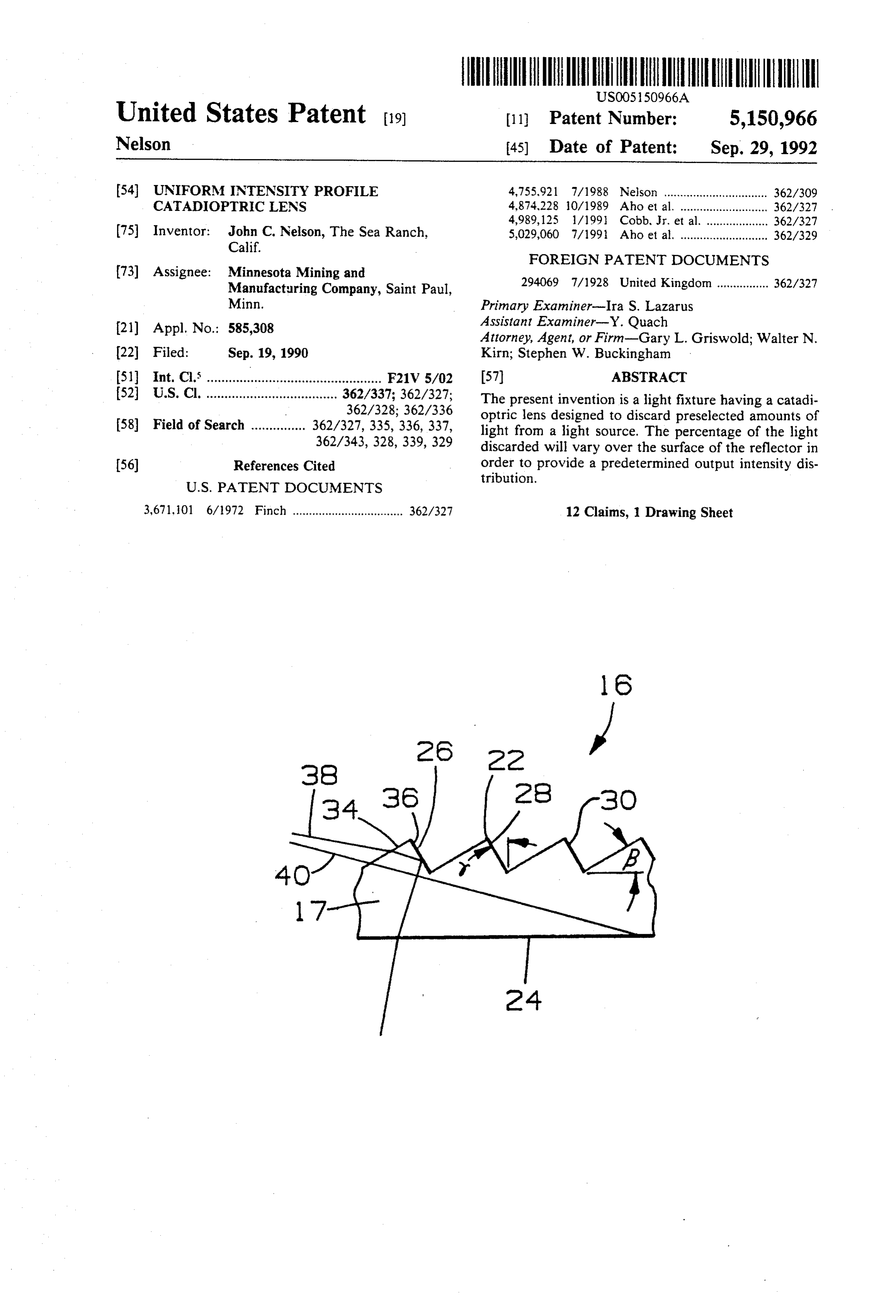
Page 1 — bibliographic record
United States Patent (19) 11 Patent Number: 5,150,966 Nelson 45) Date of Patent: Sep. 29, 1992 (54) UNIFORM INTENSITY PROFILE 4,755,921 7/1988 Nelson ................................ 362/309 CATADIOPTRC LENS 4,874,228 10/1989 Aho et al. ... 362/327 4,989,125 l/199 Cobb, Jr. et al. ... ... 362/327 75) Inventor: John C. Nelson, The Sea Ranch, 5,029,060 7/1991 Aho et al. ........................... 362/329 Calif.
FOREIGN PATENT DOCUMENTS
73) Assignee: Minnesota Mining and 2.94069 7/1928 United Kingdom ................ 362/327 Manufacturing Company, Saint Paul,
Minn. Primary Examiner-Ira S. Lazarus 21) Appl. No.: 585,308 Assistant Examiner-Y. Quach
Attorney, Agent, or Firm-Gary L. Griswold; Walter N.
22 Filed: Sep. 19, 1990 Kirn; Stephen W. Buckingham 5 Int. Cl. ............r F21V 5/02 57) ABSTRACT 52 U.S. Cl. .................................... 362/337; 362/327; The present invention is a light fixture having a catadi 362/328; 362/336 optric lens designed to discard preselected amounts of 58) Field of Search ............... 362/327, 335, 336, 337, light from a light source. The percentage of the light 362/343, 328,339, 329 discarded will vary over the surface of the reflector in (56) References Cited order to provide a predetermined output intensity dis tribution.
3,671, 01 6/1972 Finch .................................. 362/327 12 Claims, 1 Drawing Sheet
Page 2
Drawing sheet — no readable text.
Page 3
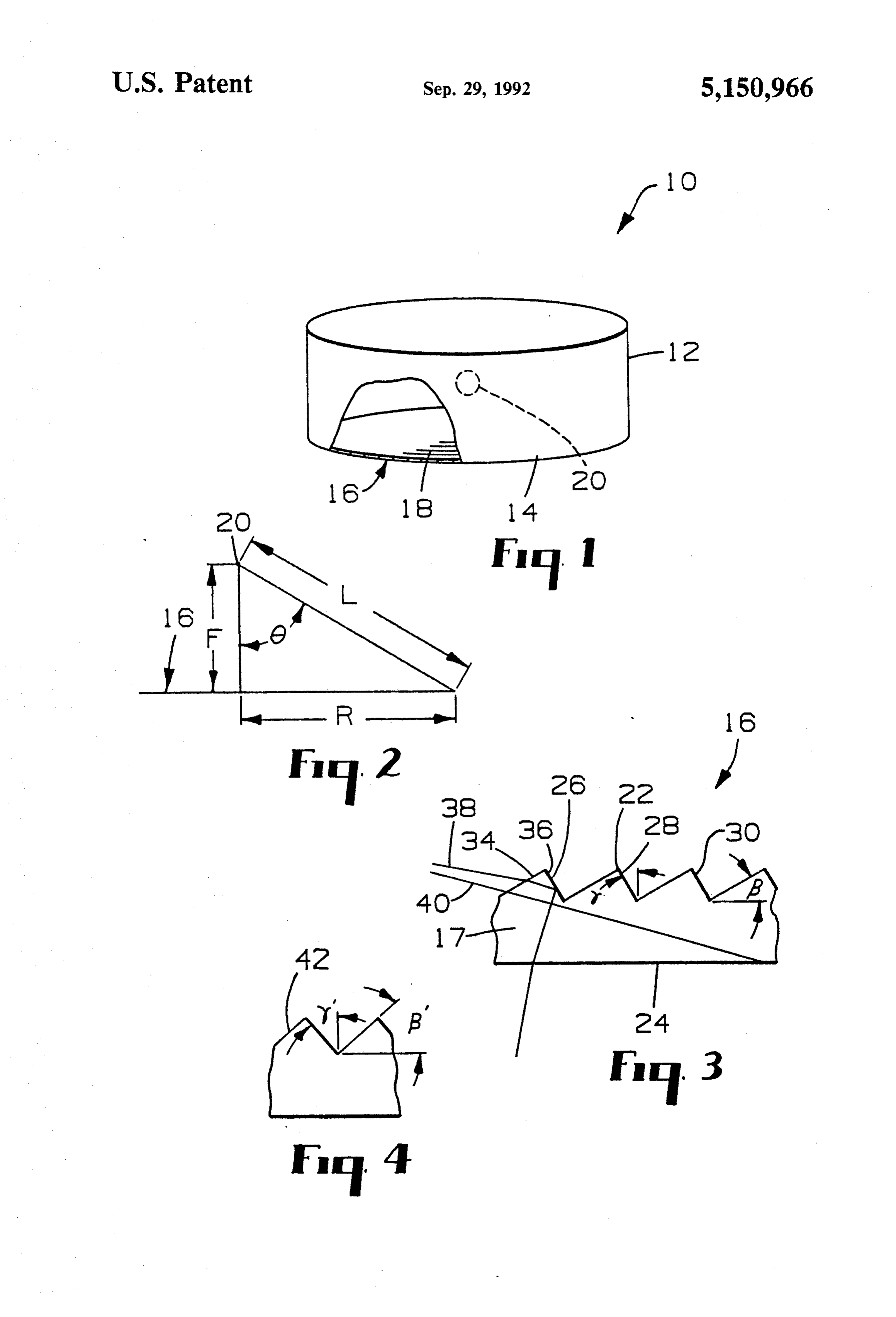
used in the subsequent description. F is the focal length
UNIFORM INTENSITY PROFILE CATADIOPTRIC of lens 16 and represents the distance between light LENS source 20 and lens 16. R is the radial distance from the
BACKGROUND OF THE INVENTION
center of lens 16 to a point under consideration. L is the 5distance from light source 20 to the point under consid
A common desire in designing a lighting fixture is to eration. The angle of incidence of a light ray on lens 16 provide such a fixture such that it will provide a uni is identified as 6.
form level of illumination across its entire aperture. The goal in designing a light fixture according to the Various techniques have been used to accomplish this. O invention is to provide the appearance of a uniform For example, one such light fixture is shown in com light intensity across the aperture. The expression ap monly-assigned U.S. Pat. 4,791,540. The system of that pearance is used because, in most situations, some varia patent uses specialized film in the aperture in order to tion will not be noticeable. Typically an intensity ratio ensure that the light will undergo multiple reflections as great as three to one from the brightest to darkest before emerging. In this way the light is evenly distrib region will not be noticed. Because the appearance of uted throughout the optical cavity providing a uniform 15 uniform intensity is provided by effectively discarding intensity output.
Another technique is shown in commonly-assigned some tion of the light, allowing the actual intensity distribu to be less than totally uniform provides greater copending application Ser. No. 192,212, filed May 10, efficiency.
1988. According to the technique taught therein, a Fres Thus the designer of a light fixture must specify a nel-type reflector is provided wherein some of the Fres 20 desired intensity profile for the aperture of the fixture. nel structures have multiple active faces. Some of these Such a profile may be expressed as shown below. faces are used to direct light out of the light fixture in the intended direction, while others are used to discard excess light in areas close to the light source.
SUMMARY OF THE INVENTION In this expression I is the intensity of the light projected According to the invention a light fixture has a hous on the optical window expressed as a function of the ing defining an optical cavity with an optical window radial distance from the center of aperture. V is the permitted variation in intensity, expressed as a ratio of for allowing light to escape from the housing. The light fixture further has a light source within the optical 30 the brightest to darkest region. Rax is the distance from cavity. A lens lies in said optical window and has a first the center of the aperture to the outer edge. Rnin is the radius of a central zone that is excluded from the calcu surface external to the optical cavity and a second sur face internal to the optical cavity. The second surface is lation. If the region of uniformity is to go to the center a structured surface. The structured surface has a plu of the aperture, Rnin is set equal to zero. rality of triangular prisms formed thereon. Each of the 35 The actual intensity profile obtained from a light triangular prisms has a transmissive facet and a reflec fixture may be expressed as tive facet, the transmissive facets making first angles with the optical window and the reflective facets mak ing second angles with a normal to the optical window, where T is the transmission function of the lens ex where the first and second angles for each prism are 40 chosen such that the light fixture will provide a prese pressed as a function of R and d(0) is the light source lected light intensity distribution over the optical win intensity as a function of incident angle. For an ideal dow. source d(6) is constant, but for a real source it may be necessary to consider it. In this expression a is a propor
BRIEF DESCRIPTION OF THE DRAWINGS 45 tionality constant.
FIG. 1 is a view of a light fixture according to the Combining these equations yields: invention;
FIG. 2 is a schematic diagram of a light fixture ac cording to the invention;
FIG. 3 is a side view of a first portion of a lens for use 50 where Tmax is value of the transmission function at in a light fixture according to the invention; and Rmax and 6max is the value of 6 at Rmax. Once the trans FIG. 4 is a side view of a second portion of a lens for mission function has been defined, a lens is designed to use in a light fixture according to the invention. provide that transmission function. That may be done iteratively, using a ray trace model.
DETAILED DESCRIPTION OF A PREFERRED FIG. 3 illustrates a portion of a typical lens that may EMBODIMENT be used as lens 16. Lens 16 is of a transparent material FIG. 1 illustrates an embodiment of the invention. In such as polycarbonate or an acrylic material. In the FIG. 1 a light fixture, 10, includes a housing 12 defining embodiment of FIG. 3, lens 16 has a structured surface, an optical cavity. It also includes an optical window 14 22, and a smooth surface, 24. Structured surface. 22 has through which the light escapes. In a preferred embodi structures 26, 28, and 30. It should be noted that the ment the optical window lies in a plane. Furthermore it term "smooth' as used to describe surface 24 is a rela includes a catadioptric lens, 16, having a structured tive term and the surface could have a matte finish in surface and lying in optical window 14. The structures order that a vapor coated metal on surface 24 would are schematically shown as 18 and are typically circular provide a diffuse reflector. In other embodiments sur and concentric. Light fixture 10 also includes a light 65 face 24 could have structures thereon. Typical struc source, 20. tures that might be desired would include pillow lenses FIG. 2 schematically shows the light fixture of the such as those used to provide the desired angular distri invention in order to define some of the symbols to be bution of light output in an automative taillight.
Page 4
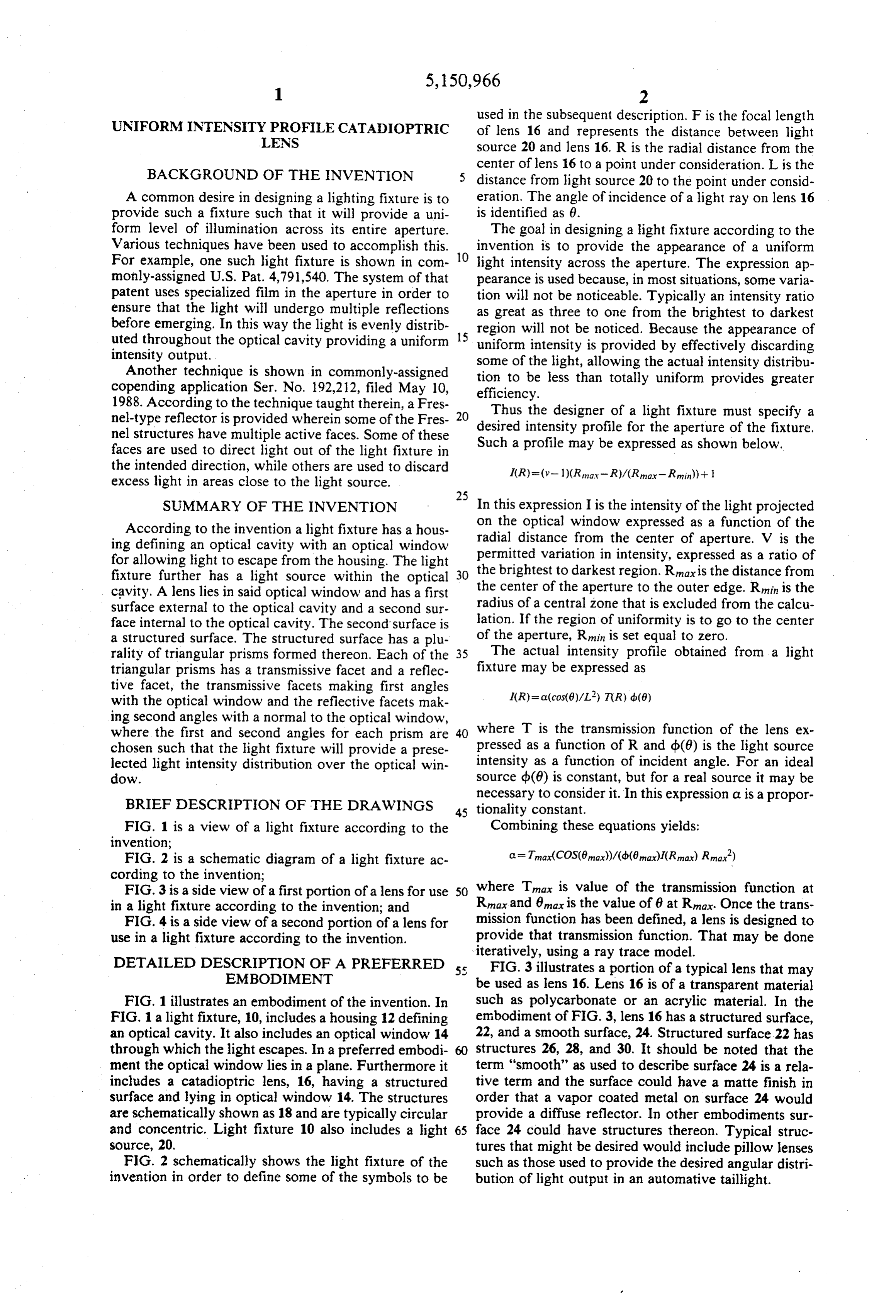
Structures 26 on structured surface 22 has facets 34 What is claimed is:
and 36 making it a triangular prism. A light ray, 38, 1. A light fixture comprising: from light source 20, enters lens 16 through facet 34 and a housing defining an optical cavity having an optical is refracted. Light ray 38 then travels across structure window for allowing light to escape from said 26 to facet 36 where it undergoes total internal reflec optical cavity;
tion. Thus facet 34 may be called a transmissive facet a light source in said optical cavity for producing and facet 36 may be called a reflective facet. Alterna light; and tively light ray 40 enters lens 16 through transmissive a lens lying in said optical window for directing light facet 34 but misses reflective surface 36. In the example from said optical cavity through said optical win of FIG. 3 it is totally internally reflected by surface 24 10 dow, said lens having a first surface external to said although in some situations it would be transmitted at a optical cavity and a second surface internal to said large angle to the primary output direction of the light optical cavity, said second surface being a struc ing element. In either case it is effectively discarded. tured surface, said structured surface having a plu The shape of each of the structures on structured rality of triangular prisms formed thereon, each surface 22 is defined by the selection of two angles, 15 said prisms having a transmissive facet and a reflec identified as angles (3 and y on structure 26 and by the tive facet positioned such that light from said light width of the prism. Angle f3 is the angle between trans source will enter said lens through one of said missive facet 34 and smooth surface 24 while angle y is transmissive facets, be totally internally reflected the angle between reflective facet 36 and a normal to by one of said reflective facets and exit through smooth surface 24. Angle (3 and the groove width are 20 said first surface, where each of said transmissive chosen to provide the desired transmission function for facets makes a first angle with said optical window a particular position on lens 16 and angle y is chosen to and each of said reflective facets makes a second insure that the light emerges through optical window 14 angle with a normal to said optical window, said in the desired direction. first and second angles for each of said prisms being By way of contrast with the structures shown in FIG. 25 selected to provide preselected light intensity dis 3, which might be designed to be positioned relatively tribution over said optical windown, said prese close to light source 20, structure 42 of FIG. 4 would be lected light intensity distribution being provided by intended for use at a greater val of R. As may be seen discarding a preselected percentage of said light the sizes (3' and y' of structure 42 are greater than those from said light source.
of g and y of structure 26 of FIG. 3. 30 2. The light fixture of claim 1 wherein said triangular
EXAMPLE
prisms are circular and concentric.
3. The light fixture of claim 2 wherein said prese
A lens was designed for a light fixture having a focal lected light intensity distribution has a region of greatest length of 0.6 inches, an Rnin of 0.0 inch, an Rnax of 5 intensity and a region of least intensity and said region inches, a fall-off factor (V) of 3 and a constant source 35 of greatest intensity has an intensity no more than three angular intensity distribution. Given these assumptions times as great as that in said region of least intensity. the following lens described in the table below was 4. The light fixture of claim 3 wherein said first sur designed. face is smooth.
5. The light fixture of claim 4 wherein said optical 40 window lies in a plane.
(inches) (degrees) (degrees) inches 6. The light fixture of claim 1 wherein said prese
lected intensity distribution has a region of greatest
intensity and a region of least intensity and said region .05 25.988 6.397 002 of greatest intensity has an intensity no more than three .1 2.5 6.972 005 45 times as great as that in said region of least intensity.
7. The light fixture of claim 1 wherein said first sur
face is smooth.
S 10.30 14.96 .01 8. The light fixture of claim 7 wherein said prese .6 15.822 O1 lected light intensity ion has a region of greatest inten .7 2 17.258 O1 50 sity and a region of least intensity and said region of .8 12.94 18.476 .01 greatest intensity has an intensity no more than three
5.5 20.621 .01 times as great as that in said region of least intensity. 1.3 19.04 22.551 .01 9. The light fixture of claim 7 wherein said optical
window lies in a plane.
2.5 29,658 28.522 0. 10. The light fixture of claim 1 wherein said optical 3 30.72 29.323 .01 window lies in a plane.
3.5 32.5 30,166 .01 11. The light fixture of claim 10 wherein said triangu
lar prisms are circular and concentric.
5 40 32.774 .01 12. The light fixture of claim 11 wherein said first surface is smooth.
Page 5
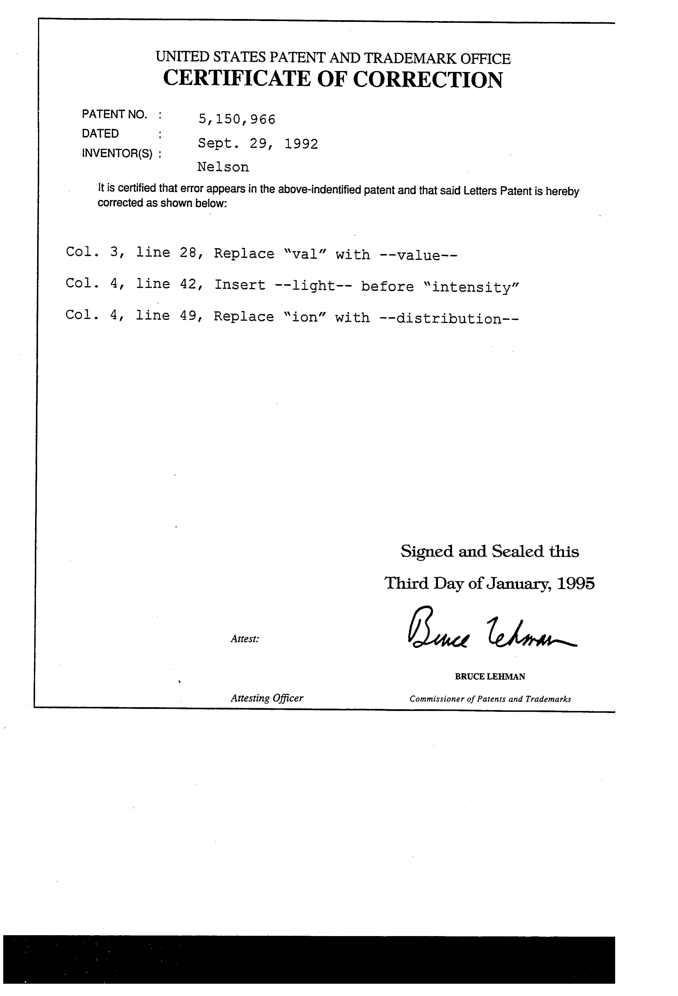
UNITED STATES PATENT ANDTRADEMARK OFFICE
CERTIFICATE OF CORRECTION
DATED
Nelson it is certified that error appears in the above-indentified patent and that said Letters Patent is hereby Corrected as shown below:
Col. 3, line 28, Replace val' with --value-- Col. 4, line 42, Insert --light-- before intensity" Col. 4, line 49, Replace ion' with --distribution--
Signed and Sealed this
Third Day of January, 1995
BRUCELEHMAN
Attesting Officer Commissioner of Patents and Trademarks
Provenance
- Collection
- Cited prior art
- Original PDF
- patentimages.storage.googleapis.com →
- Filed
- 1990-09-19
- Pages
- 5
- Method
- pdftotext (the PDF's own text layer) + pdftoppm 300dpi page scans
- Source
- Google Patents bibliographic record
- Granted
- 1992-09-29
- Inventors
- John C. Nelson; Minnesota Mining and Manufacturing Co
- Transcribed from
- patentimages.storage.googleapis.com →