patent · US4050789
Tracking lens system for solar collectors and skylights
27 September 1977
Page 1 — bibliographic record
United States
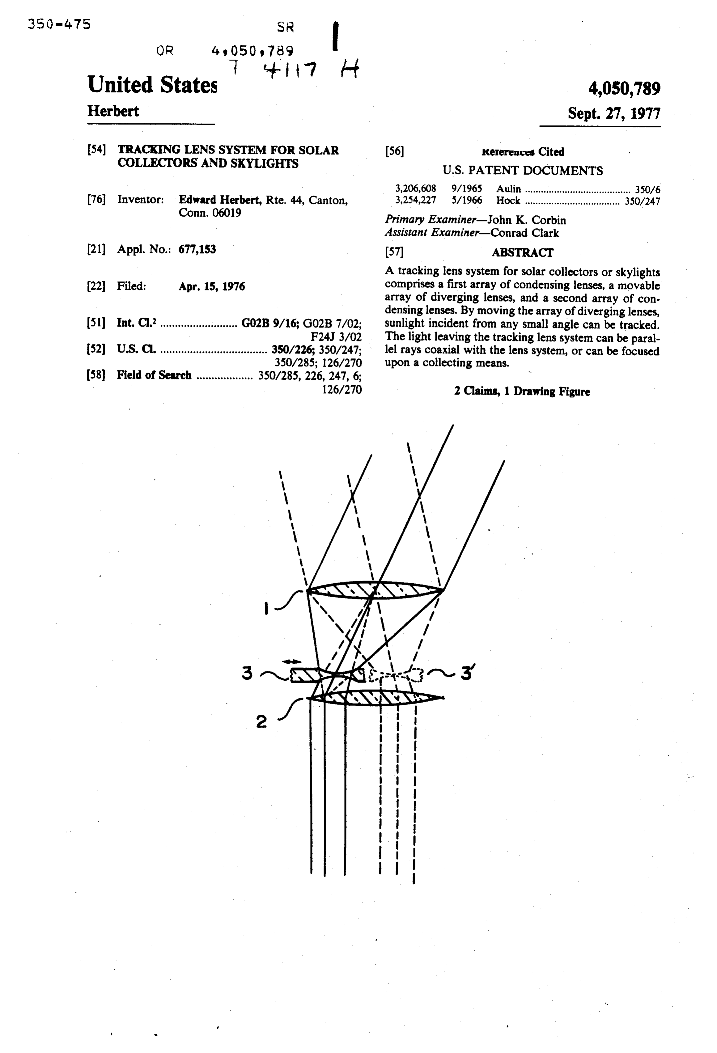
Herbert Sept. 27, 1977 (54) TRACKING LENS SYSTEM FOR SOLAR (56) Kererences Cited COLLECTORS AND SKYLIGHTS U.S. PATENT DOCUMENTS 3,206,608 9/1965 Aulin ........................................ 350/6 76 Inventor: Edward Herbert, Rte. 44, Canton, 3,254,227 5/1966 Hock .................................... 350/247
Primary Examiner-John K. Corbin
Assistant Examiner-Conrad Clark (21) Appl. No.: 677,153 (57) ABSTRACT A tracking lens system for solar collectors or skylights 22 Filed: Apr. 15, 1976 comprises a first array of condensing lenses, a movable array of diverging lenses, and a second array of con densing lenses. By moving the array of diverging lenses, 51) Int. Cl........................... G02B 9/16; G02B 7/02; sunlight incident from any small angle can be tracked. F24J 3/02 The light leaving the tracking lens system can be paral 52 U.S. C. .................................... 350/226; 350/247; lel rays coaxial with the lens system, or can be focused
Page 2
Drawing sheet — no readable text.
Page 3
with the incident light, and the apex of which would fall
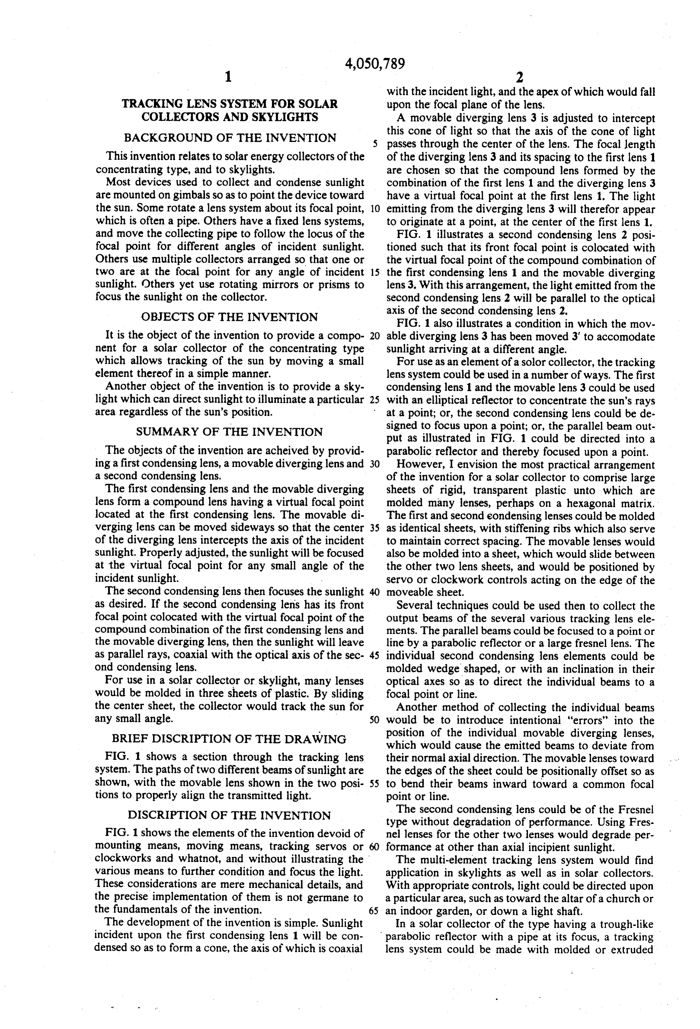
TRACKING LENS SYSTEM FOR SOLAR upon the focal plane of the lens, COLLECTORS AND SKYLIGHTS A movable diverging lens 3 is adjusted to intercept BACKGROUND OF THE INVENTION this cone of light so that the axis of the cone of light passes through the center of the lens. The focal length
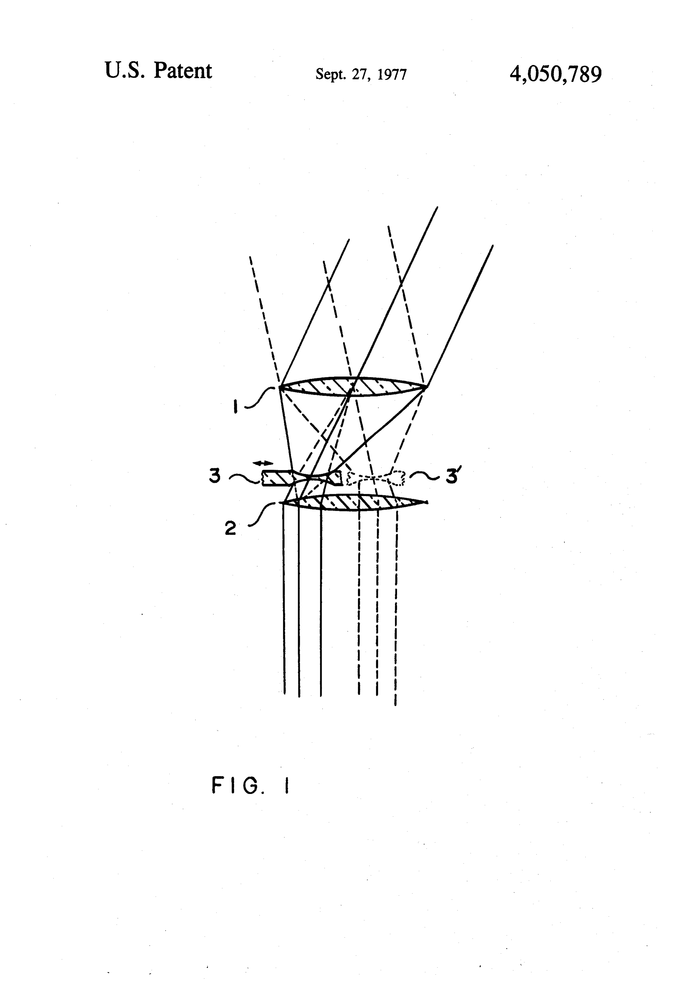
This invention relates to solar energy collectors of the of the diverging lens 3 and its spacing to the first lens 1 concentrating type, and to skylights. are chosen so that the compound lens formed by the Most devices used to collect and condense sunlight combination of the first lens 1 and the diverging lens 3 are mounted on gimbals so as to point the device toward have a virtual focal point at the first lens 1. The light the sun. Some rotate a lens system about its focal point, 10 emitting from the diverging lens 3 will therefor appear which is often a pipe. Others have a fixed lens systems, to originate at a point, at the center of the first lens 1. and move the collecting pipe to follow the locus of the FIG. 1 illustrates a second condensing lens 2 posi focal point for different angles of incident sunlight. tioned such that its front focal point is colocated with Others use multiple collectors arranged so that one or the virtual focal point of the compound combination of two are at the focal point for any angle of incident 15 the first condensing lens 1 and the movable diverging sunlight. Others yet use rotating mirrors or prisms to lens 3. With this arrangement, the light emitted from the focus the sunlight on the collector. second condensing lens 2 will be parallel to the optical OBJECTS OF THE INVENTION axis of the second condensing lens 2.
FIG. 1 also illustrates a condition in which the mov
It is the object of the invention to provide a compo 20 able diverging lens 3 has been moved 3' to accomodate nent for a solar collector of the concentrating type sunlight arriving at a different angle. which allows tracking of the sun by moving a small For use as an element of a solor collector, the tracking element thereof in a simple manner. lens system could be used in a number of ways. The first Another object of the invention is to provide a sky condensing lens 1 and the movable lens 3 could be used light which can direct sunlight to illuminate a particular 25 with an elliptical reflector to concentrate the sun's rays area regardless of the sun's position. at a point; or, the second condensing lens could be de SUMMARY OF THE INVENTION signed to focus upon a point; or, the parallel beam out put as illustrated in FIG. 1 could be directed into a
The objects of the invention are acheived by provid parabolic reflector and thereby focused upon a point. ing a first condensing lens, a movable diverging lens and 30 However, I envision the most practical arrangement a second condensing lens. of the invention for a solar collector to comprise large The first condensing lens and the movable diverging sheets of rigid, transparent plastic unto which are lens form a compound lens having a virtual focal point molded many lenses, perhaps on a hexagonal matrix. located at the first condensing lens. The movable di The first and second eondensing lenses could be molded verging lens can be moved sideways so that the center 35 as identical sheets, with stiffening ribs which also serve of the diverging lens intercepts the axis of the incident to maintain correct spacing. The movable lenses would sunlight. Properly adjusted, the sunlight will be focused also be molded into a sheet, which would slide between at the virtual focal point for any small angle of the the other two lens sheets, and would be positioned by incident sunlight. servo or clockwork controls acting on the edge of the The second condensing lens then focuses the sunlight moveable sheet.
as desired. If the second condensing lens has its front Several techniques could be used then to collect the focal point colocated with the virtual focal point of the output beams of the several various tracking lens ele compound combination of the first condensing lens and ments. The parallel beams could be focused to a point or the movable diverging lens, then the sunlight will leave line by a parabolic reflector or a large fresnel lens. The as parallel rays, coaxial with the optical axis of the sec 45 individual second condensing lens elements could be ond condensing lens. molded wedge shaped, or with an inclination in their For use in a solar collector or skylight, many lenses optical axes so as to direct the individual beams to a would be molded in three sheets of plastic. By sliding focal point or line.
the center sheet, the collector would track the sun for Another method of collecting the individual beams any small angle. 50 would be to introduce intentional "errors' into the BRIEF DISCRIPTION OF THE DRAWING position of the individual movable diverging lenses, which would cause the emitted beams to deviate from
FIG. 1 shows a section through the tracking lens their normal axial direction. The movable lenses toward system. The paths of two different beams of sunlight are the edges of the sheet could be positionally offset so as shown, with the movable lens shown in the two posi 55 to bend their beams inward toward a common focal tions to properly align the transmitted light. point or line.
DISCRIPTION OF THE INVENTION The second condensing lens could be of the Fresnel type without degradation of performance. Using Fres
FIG. 1 shows the elements of the invention devoid of nel lenses for the other two lenses would degrade per mounting means, moving means, tracking servos or 60 formance at other than axial incipient sunlight. clockworks and whatnot, and without illustrating the The multi-element tracking lens system would find various means to further condition and focus the light. application in skylights as well as in solar collectors. These considerations are mere mechanical details, and With appropriate controls, light could be directed upon the precise implementation of them is not germane to a particular area, such as toward the altar of a church or the fundamentals of the invention. 65 an indoor garden, or down a light shaft. The development of the invention is simple. Sunlight In a solar collector of the type having a trough-like incident upon the first condensing lens 1 will be con parabolic reflector with a pipe at its focus, a tracking densed so as to form a cone, the axis of which is coaxial lens system could be made with molded or extruded
Page 4
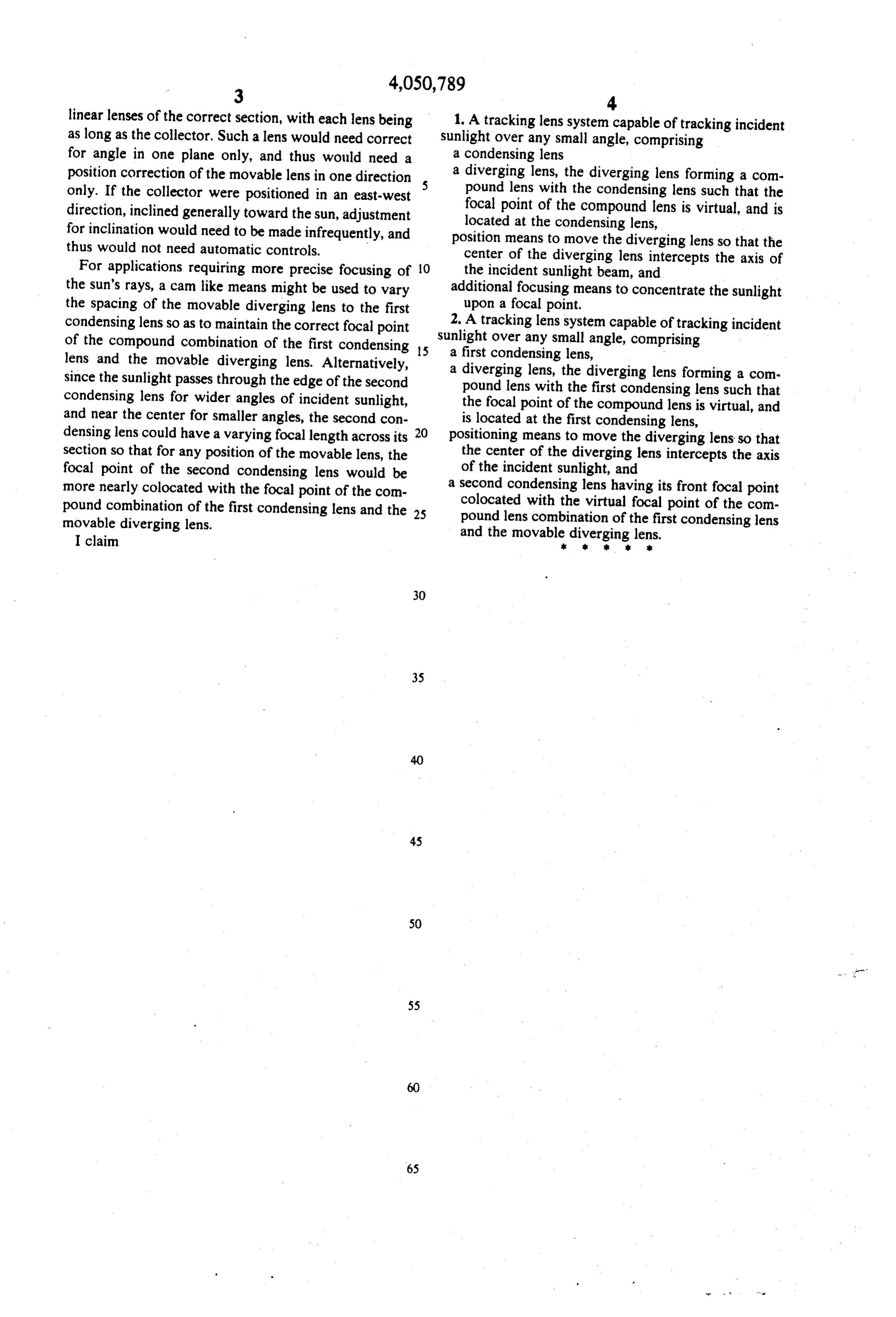
linear lenses of the correct section, with each lens being 1. A tracking lens system capable of tracking incident as long as the collector. Such a lens would need correct sunlight over any small angle, comprising for angle in one plane only, and thus would need a a condensing lens position correction of the movable lens in one direction a diverging lens, the diverging lens forming a com only. If the collector were positioned in an east-west pound lens with the condensing lens such that the direction, inclined generally toward the sun, adjustment focal point of the compound lens is virtual, and is for inclination would need to be made infrequently, and located at the condensing lens, thus would not need automatic controls. position means to move the diverging lens so that the center of the diverging
For applications requiring more precise focusing of 10 the incident sunlight beam, lens intercepts the axis of and the sun's rays, a cam like means might be used to vary additional focusing means to concentrate the sunlight the spacing of the movable diverging lens to the first upon a focal point.
condensing lens so as to maintain the correct focal point 2. A tracking lens system capable of tracking incident of the compound combination of the first condensing is sunlighta first over any small angle, comprising condensing lens, lens and the movable diverging lens. Alternatively, a diverging lens, the diverging lens forming a com since the sunlight passes through the edge of the second pound lens with the first condensing lens such that condensing lens for wider angles of incident sunlight, the focal point of the compound lens is virtual, and and near the center for smaller angles, the second con is located at the first condensing lens, densing lens could have a varying focal length across its 20 positioning means to move the diverging lens so that section so that for any position of the movable lens, the the center of the diverging lens intercepts the axis focal point of the second condensing lens would be of the incident sunlight, and more nearly colocated with the focal point of the com a second condensing lens having its front focal point pound combination of the first condensing lens and the 25 colocated with the virtual focal point of the com pound lens combination of the first condensing lens movable diverging lens. and the movable diverging lens. I claim is
Provenance
- Collection
- Cited prior art
- Original PDF
- patentimages.storage.googleapis.com →
- Filed
- 1976-04-15
- Pages
- 4
- Method
- pdftotext (the PDF's own text layer) + pdftoppm 300dpi page scans
- Source
- Google Patents bibliographic record
- Granted
- 1977-09-27
- Inventors
- Edward Herbert
- Transcribed from
- patentimages.storage.googleapis.com →