patent · US2469080
Unitary lens unit
3 May 1949
Page 1
Drawing sheet — no readable text.
Page 2
Drawing sheet — no readable text.
Page 3
Patented May 3, 1949 2,469,080
UNITED STATES PATENT OFFICE
UNITARY LENS UNIT
Seymour Rosin and George M. Cressaty, New
York, N. Y.; said Rosin assignor to said
Cressaty
Application May 9, 1945, Serial No. 592,742
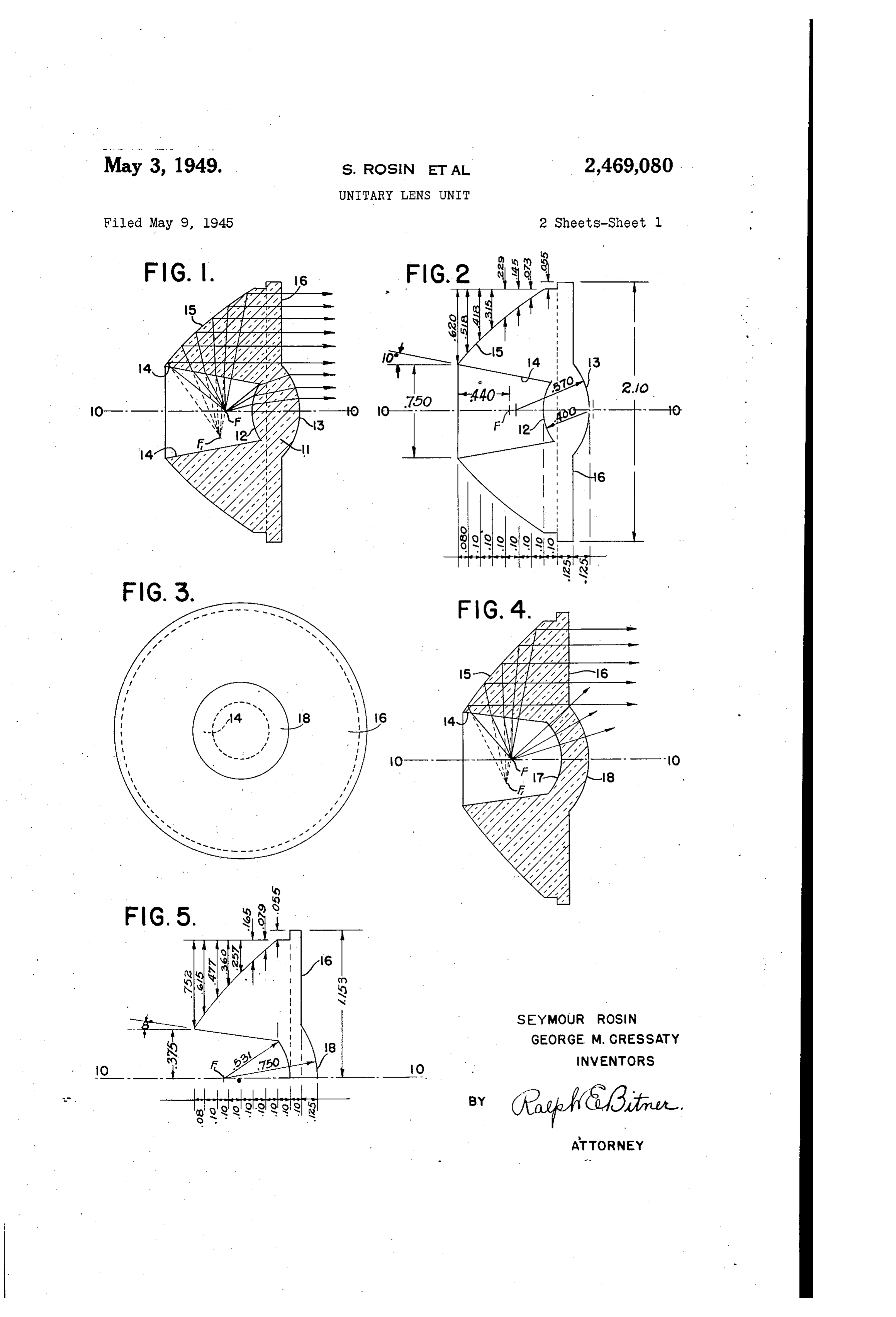
This invention relates to lens units that may be in diameter than a paraboloid metal reflector used to focus a beam of light from a concentrated having the same light gathering scope. source. It more particularly relates to that type Another object of the invention is to reduce the of lens unit Which utilizes both reflection and re cost of manufacturing such lens systems by de fraction in order to produce a desired beam of Signing the component surfaces so that the article light. may be molded in a simple single cavity mold. The focussing device generally used with beam Another object of the invention is to obtain flashlights consists of a parabolic reflector sur compiete utilization of almost all the rays given rounding the lamp With a piece of plane glass in Off by a Small lamp by constructing the lens sys front of both to protect them from dirt. The 10 ten so that part of the rays are reflected into a shape of the reflector is generally a true para parallel beam while the remainder are refracted boloid since it is the surface of revolution of a into a similar and parallel beam. parabola about its axis. While such a focussing Other objects and structural details of the in device is widely used, there are several disad vention will be apparent from the following de Wantages inherent to this type. First, there is a 5 Scription when read in connection with the ac tendency of the reflector to tarnish after con companying drawings, wherein tinued usage. Second, the reflecting surface even Fig. 1 is a Cross sectional view of one form of When new is not of the highest efficiency. And the lens and shows the paths of a number of light third, the reflector must be rade of considerable rays from the focal point to a parallel beam. diameter if it is to include a large percentage of 20 Fig. 2 is also a cross sectional view of the same the rays from the lamp. lens but shows the structural dimensions of all Lenses that both reflect and refract are not new surfaces.
in the art and a U. S. patent to Harris, No. Fig. 3 is an elevational View of the lens shown 2,254,961, and Harris and Bittner Patent No. in Fig. 2.
2.254962 describe some forms and Shapes that are 2. Fig. 4 is a cross Sectional view of an alternate useful for increasing the focussing efficiency of a form of lens wherein the axial rays are not focused lamp with a concentrated source. but are allowed to spread out to give general The present invention has been designed to illumination.
overcome all the objections to the well-known Fig. 5 is a cross sectional view of the same lens parabolic reflector and to present some improve 30 shown in Fig. 4 but shows the dimensional struct ments over the designs disclosed in the above men ture of all the surfaces.
tioned patents. Fig. 6 is an elevational view of the lens shown The present invention resides in a unitary in Fig. 4.
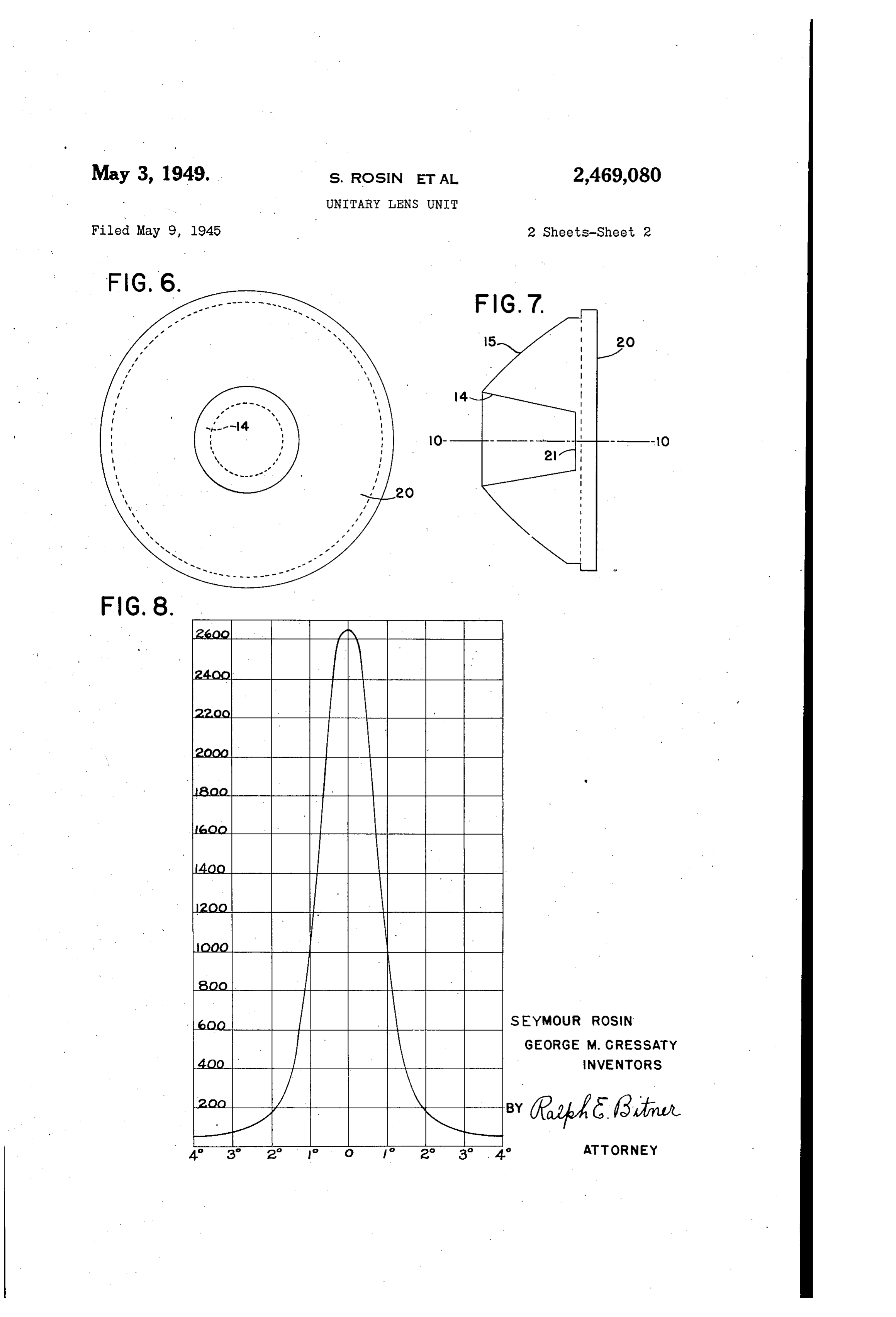
lens block having two principal modes of beam Fig. 7 is a cross sectional view of another alter formation. A central lens mounted on the optical 35 nate form of the invention similar to Fig. 4 but axis refracts light rays from the Source and sends having a plane OutSide face.
them out in a parallel beam of light. A marginal Fig. 8 is a graph showing the distribution of lens block receives the marginal rays and after beam candlepower plotted against degrees away transmittal through the block they are reflected from the optical axis.
by the surface which forms the outer boundary of 40 Referring now to Fig. 1, the point F on the the block. This surface, as will be hereinafter Ogtical axis 8-9 denotes the position of the described, is not a paraboloid but is formed by the ight source, Axial rays move to the right and surface of revolution of a parabola, about an axis enter a bull's eye lens through a spherical parallel but not coincident with the parabolic Surface 2. After traversing the thickness of the XS. 45 less, the rays emerge through surface 3 and One of the objects of the invention is to obtain travel parallel to the axis O-O in the usual a single unitary focussing device by which nearly manner. The curvatures and other character all the light from a small light bulb may be con istics of lens it are not important as long as the centrated into a parallel beam. lens is positioned so that its focal point coincides Another object of the invention is to secure a 50 With the Source of light.
high reflection efficiency without the use of The marginal rays travel from the Source F to metallic reflecting Surfaces. Ward the sides of conical cavity 8 and as the Another object of the invention is to provide a rays enter the lens block they are refracted lens block Which has an efficient light gathering through a definite angle so that they continue on characteristic but which is appreciably Smaller 55 the inside of the block in a direction away from
Page 4
the point F1. After traversing the block the the variation of beam candlepower plotted rays strike surface 5 where they are totally re against degrees measured on each side of the flected. A section of surface 5 as shown in Figs. optical axis.
1, 2, 4, and 5 is part of a parabola, which has its A Single intense beam of light is not always de focal point at F1 and its axis is a line drawn Sirable and the alternate form shown in Figs. 4, through F1 and parallel to the line 0-0. HoW 5, and 6 is designed to provide a general weak ever, to generate the surface 5, the parabola, field of illumination around the central beam. must be revolved about line 0-9 and not about In this alternate form the marginal rays are its own axis. Therefore, surface 5 is not a para treated in the same manner as in the first form bola, but is a higher order surface Which has no O and all the rays which Strike the surface 5 are definite name. After reflection the light rayS reflected into a parallel beam. The paraxial rays, travel in a parallel beam to the exit surface 6 however, first strike a curved surface 7 then where they emerge Without change of direction. traverse a small length of glass and emerge at In prior art descriptions of lenses having some Surface f8 without any change in direction. Both what similar shapes, the true nature of the back 5 Spherical Surfaces and 8 have their centers reflecting surface was generally not understood at the point F where the source of light is placed nor correctly described. The sectional view, Fig. and for this reason light rays originating at F 1, consists of two equal parabola S, the foci of Will not be bent from their original path. When which are far from being coincident. If the tranversing the glass wall.
parabolas are extended until they intersect, the 20 Fig. 7 ShoWS another variation which is easier point of intersection Will be a "pole,' or a point to manufacture but does not have as much space On a surface which has discontinuous first and for a lamp bulb. The optical characteristics are Second derivatives. the same as the lens shown in Figs. 4, 5, and 6. The displaced foci in section are in reality two While a detailed portrayal has been given of points on a circle in Space, which is traced out 25 Some of the forms the invention may take, not by rotation of the Section about the axis of the Only in its Optical characteristics but also in its lens. Such a circle may be termed correctly a mechanical features, it is not intended to limit “focal circle' of the surface. The only case in the invention to the above description. The in which the Surface of a lens block is a paraboloid vention may be used in connection with flash occurs when the light rays travel from the source 30 lights, Spotlights, lanterns, and headlights. into the lens block without change of direction. Either glass, transparent plastic, or any other This case is of no practical value since it involves tlanSparent substance may be used for the lens the formation of an internal spherical cavity, a unit, Various modifications may be made with molding technique that is impossible with present out departing from the spirit of the invention and day equipment. 35 the Scope of the appended claim. The phenomenon of total reflection is well We claim:
known in the art and occurs when light rays with A unitary lens unit comprising in combination, in a refractive medium strike a boundary sur a central transparent window for transmitting face at an angle from the normal which is greater paraxial rays without change of direction, a than the critical angle. The critical angle is a 40 marginal lens block having a well to receive a function of the refractive index of the refractive Source of light, a reflecting surface on the outer medium and is found by the following reiation: boundary of Said block for reflecting marginal rays from the Source of light into a parallei beam,
Sin A=.22, Said Source of light positioned on the optical axis 45 of Said reflecting Surface, said reflecting surface
Where A is the angle between the light ray and comprising a Surface of revolution of a parabola the normal to the surface and n is the refractive about an axis parallel but not coincident with index. the parabolic axis.
In all the designs shown in the drawings, total SEYMOUR ROSIN. reflection takes place at Surface 5 because of 50 GEORGE. M. CRESSATY. the peculiar design. Forming the lamp cavity
With an inclined boundary 4 contributes con REFERENCES CITED siderably to the requisite bending of the light The following references are of record in the rays So that they make the proper angle for total file of this patent:
The beam of light formed by the unit shown in UNITED STATES PATENTS Fig. 1 is composed of parallel rays and is capable Number Name Date of Creating an intense field of illumination when 325,656 Cloud -------------- Sept. 8, 1885 it strikes an object. The graph shown in Fig. 1,281,752 Bailey ------------- Oct. 15, 1918 8 is the result of a carefully made series of tests 60 2,254,961. Harris ------------ Sept. 2, 1941 by an independent testing laboratory and shows 2,254,962 Harris et al. -------- Sept. 2, 1941
Provenance
- Collection
- Cited prior art
- Original PDF
- patentimages.storage.googleapis.com →
- Filed
- 1945-05-09
- Pages
- 4
- Method
- pdftotext (the PDF's own text layer) + pdftoppm 300dpi page scans
- Source
- Google Patents bibliographic record
- Granted
- 1949-05-03
- Inventors
- Rosin Seymour; George M Cressaty; CRESSATY
- Transcribed from
- patentimages.storage.googleapis.com →