patent · US3915148
Thermostatically controlled non-tracking type solar energy concentrator
28 October 1975
Page 1 — bibliographic record
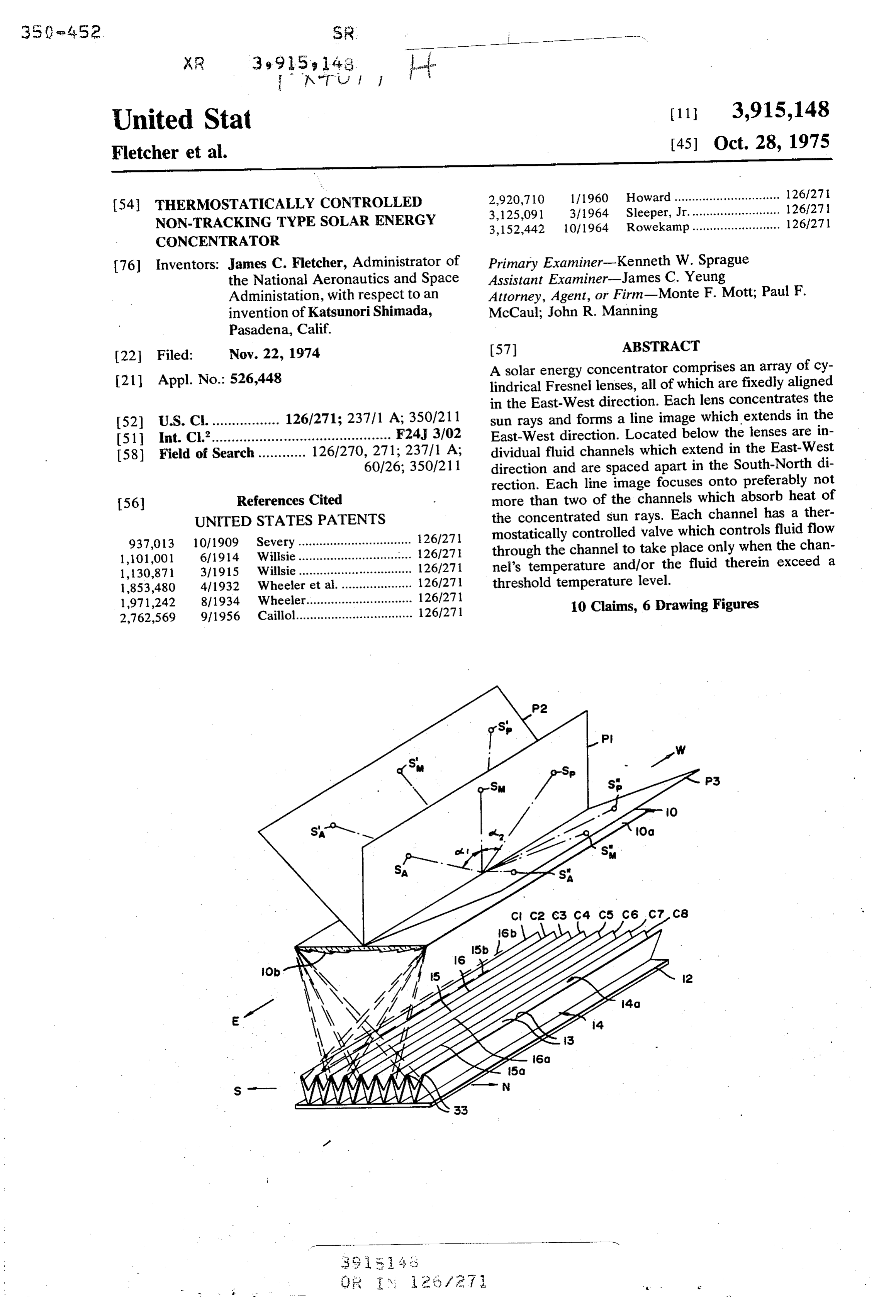
United Stat (11 3,915,148 Fletcher et al. [45] Oct. 28, 1975 2,920,710 111960 Howard.............................. 126/271 54 THERMOSTATICALLY CONTROLLED 3,125,091 3/1964 Sleeper, Jr.... ... 126/271 NON-TRACKING TYPE SOLAR ENERGY 3,152,442 10/1964 Rowekamp......................... 126/27 |
CONCENTRATOR
76) Inventors: James C. Fletcher, Administrator of Primary Examiner-Kenneth W. Sprague the National Aeronautics and Space Assistant Examiner-James C. Yeung
Administation, with respect to an Attorney, Agent, or Firm-Monte F. Mott; Paul F. invention of Katsunori Shimada, McCaul; John R. Manning
Pasadena, Calif.
22 Filed: Nov. 22, 1974 57 ABSTRACT A solar energy concentrator comprises an array of cy 21 Appl. No.: 526,448 lindrical Fresnel lenses, all of which are fixedly aligned in the East-West direction. Each lens concentrates the 52 U.S. C. ................. 126/271; 237/1 A; 350/211 sun rays and forms a line image which extends in the 51l int. Cl.’............................................. F24, 3/02 East-West direction. Located below the lenses are in 58 Field of Search ............ 126/270, 271; 237/1 A; dividual fluid channels which extend in the East-West 60/26; 350/211 direction and are spaced apart in the South-North di rection. Each line image focuses onto preferably not 56 References Cited more than two of the channels which absorb heat of UNITED STATES PATENTS the concentrated sun rays. Each channel has a ther 937,013 10/1909 Severy ................................ 126/271 mostatically controlled valve which controls fluid flow 1,101,001 6, 1914 Willsie.... ...... 126/271 through the channel to take place only when the chan 1,130,871 3, 1915 Willsie................................ 126/271 nel's temperature and/or the fluid therein exceed a 1853,480 4/1932. Wheeler et al..................... 126/271 threshold temperature level. 1971,242 8/1934. Wheeler.............................. 126/271 10 Claims, 6 Drawing Figures 2,762,569 9, 1956 Caillol................................. 126/271
Page 2
Drawing sheet — no readable text.
Page 3
Drawing sheet — no readable text.
Page 4
JUNE 2
NCIDENT ANGLE: NORMAL DECEMBER 2
GEOGRAPHICAL LOC: 42N
SKY CONDITION: CLEAR
soLAR TIME
UUNE 2
LQUID TEMP. 5 OC
INCIDENT ANGLE: NORMAL DECEMBER 2
GEOGRAPHICAL LOC: 42N
SKY CONDITION: CLEAR
SOLAR TIME
Page 5
THERMOSTATICALLY CONTROLLED South-North direction depends on the lens width in this NON-TRACKING TYPE SOLAR ENERGY direction and the concentration ratio provided by the CONCENTRATOR lens. Hereinafter the image will be referred to as a line ORIGIN OF INVENTION image. The collectors are arranged so that regardless of 5 the sun angle, which due to sun movement changes
The invention described herein was made in the per with time of day and season of the year, the line image formance of work under a NASA contract and is sub produced by each lens focuses on very few, preferably ject to the provisions of Section 305 of the National not more than two of the collector elements. Aeronautics and Space Act of 1958, Public Law The novel features of the invention are set forth with 85-568 (72 Stat. 435; 42 USC 2457). 10 particularity in the appended claims. The invention will BACKGROUND OF THE INVENTION best be understood from the following description when read in conjunction with the accompanying draw 1. Field of the Invention: lings.
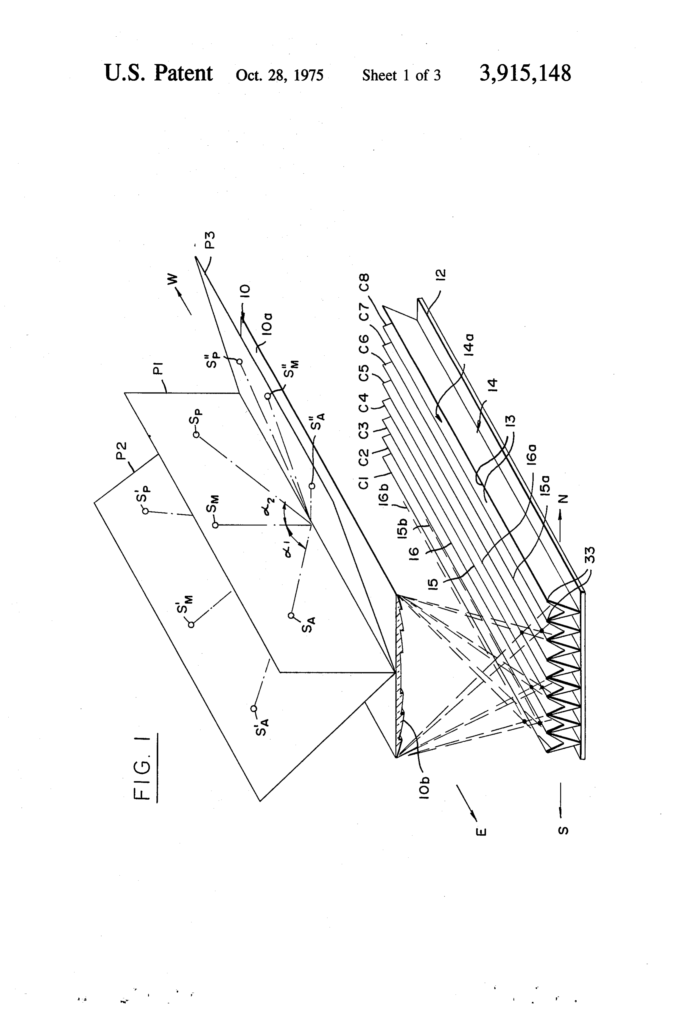
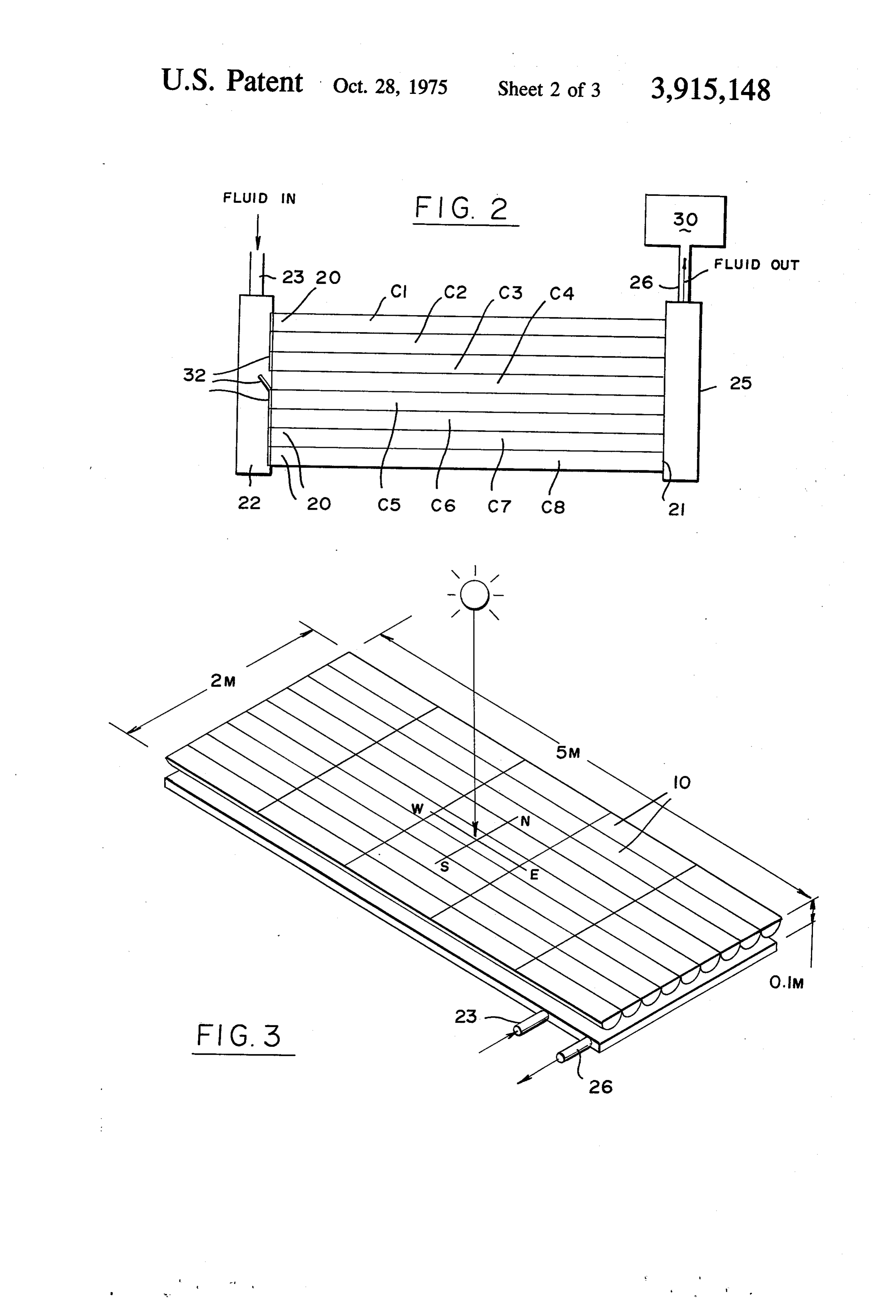
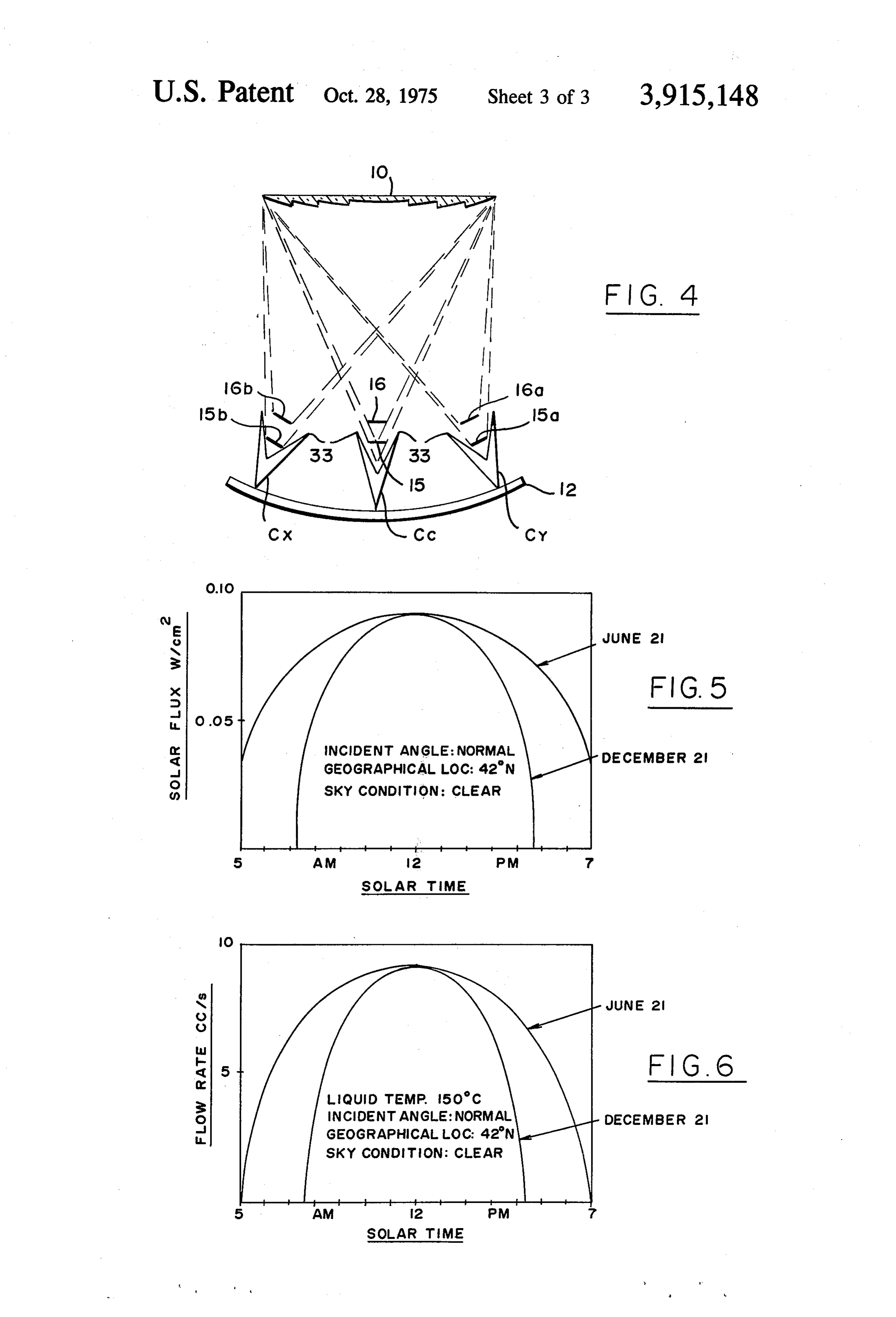
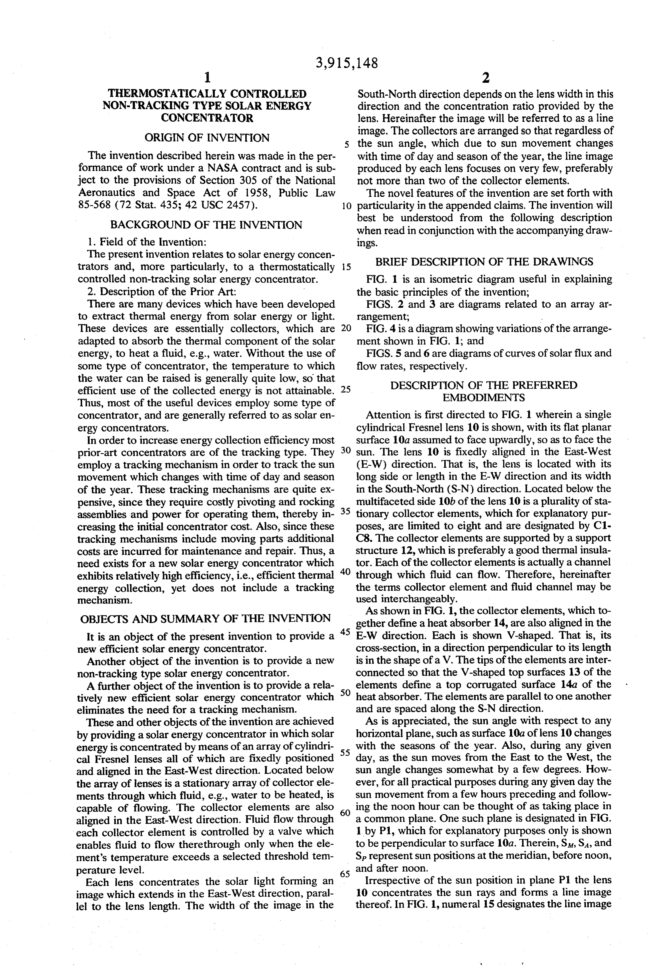
The present invention relates to solar energy concen trators and, more particularly, to a thermostatically 5 BRIEF DESCRIPTION OF THE DRAWINGS controlled non-tracking solar energy concentrator. FIG. 1 is an isometric diagram useful in explaining 2. Description of the Prior Art: the basic principles of the invention; There are many devices which have been developed FIGS. 2 and 3 are diagrams related to an array ar to extract thermal energy from solar energy or light. rangement;
These devices are essentially collectors, which are 20 FIG. 4 is a diagram showing variations of the arrange adapted to absorb the thermal component of the solar ment shown in FIG. 1; and energy, to heat a fluid, e.g., water. Without the use of FIGS. 5 and 6 are diagrams of curves of solar flux and some type of concentrator, the temperature to which flow rates, respectively.
the water can be raised is generally quite low, so that DESCRIPTION OF THE PREFERRED efficient use of the collected energy is not attainable. 25 EMBODIMENTS Thus, most of the useful devices employ some type of concentrator, and are generally referred to as solar en Attention is first directed to FIG. 1 wherein a single ergy concentrators. cylindrical Fresnel lens 10 is shown, with its flat planar In order to increase energy collection efficiency most surface 10a assumed to face upwardly, so as to face the prior-art concentrators are of the tracking type. They 30 sun. The lens 10 is fixedly aligned in the East-West employ a tracking mechanism in order to track the sun (E-W) direction. That is, the lens is located with its movement which changes with time of day and season long side or length in the E-W direction and its width of the year. These tracking mechanisms are quite ex in the South-North (S-N) direction. Located below the pensive, since they require costly pivoting and rocking multifaceted side 10b of the lens 10 is a plurality of sta assemblies and power for operating them, thereby in 35 tionary collector elements, which for explanatory pur creasing the initial concentrator cost. Also, since these poses, are limited to eight and are designated by C1 tracking mechanisms include moving parts additional C8. The collector elements are supported by a support costs are incurred for maintenance and repair. Thus, a structure 12, which is preferably a good thermal insula need exists for a new solar energy concentrator which tor. Each of the collector elements is actually a channel exhibits relatively high efficiency, i.e., efficient thermal 40 through which fluid can flow. Therefore, hereinafter energy collection, yet does not include a tracking the terms collector element and fluid channel may be mechanism. used interchangeably.
As shown in FIG. 1, the collector elements, which to
OBJECTS AND SUMMARY OF THE INVENTION gether define aheat absorber 14, are also aligned in the It is an object of the present invention to provide a 45 E-W direction. Each is shown V-shaped. That is, its new efficient solar energy concentrator. cross-section, in a direction perpendicular to its length Another object of the invention is to provide a new is in the shape of a V. The tips of the elements are inter non-tracking type solar energy concentrator. connected so that the V-shaped top surfaces 13 of the A further object of the invention is to provide a rela 50 elements define a top corrugated surface 14a of the tively new efficient solar energy concentrator which heat absorber. The elements are parallel to one another eliminates the need for a tracking mechanism. and are spaced along the S-N direction. These and other objects of the invention are achieved As is appreciated, the sun angle with respect to any by providing a solar energy concentrator in which solar horizontal plane, such as surface 10a of lens 10 changes energy is concentrated by means of an array of cylindri with the seasons of the year. Also, during any given cal Fresnel lenses all of which are fixedly positioned 55 day, as the sun moves from the East to the West, the and aligned in the East-West direction. Located below sun angle changes somewhat by a few degrees. How the array of lenses is a stationary array of collector ele ever, for all practical purposes during any given day the ments through which fluid, e.g., water to be heated, is sun movement from a few hours preceding and follow capable of flowing. The collector elements are also 60 ing the noon hour can be thought of as taking place in aligned in the East-West direction. Fluid flow through a common plane. One such plane is designated in FIG. each collector element is controlled by a valve which 1 by P1, which for explanatory purposes only is shown enables fluid to flow therethrough only when the ele to be perpendicular to surface 10a. Therein, S, SA, and ment's temperature exceeds a selected threshold tem Sp represent sun positions at the meridian, before noon,
and after noon.
Each lens concentrates the solar light forming an Irrespective of the sun position in plane P1 the lens image which extends in the East-West direction, paral 10 concentrates the sun rays and forms a line image lel to the lens length. The width of the image in the thereof. In FIG. 1, numeral 15 designates the line image
Page 6
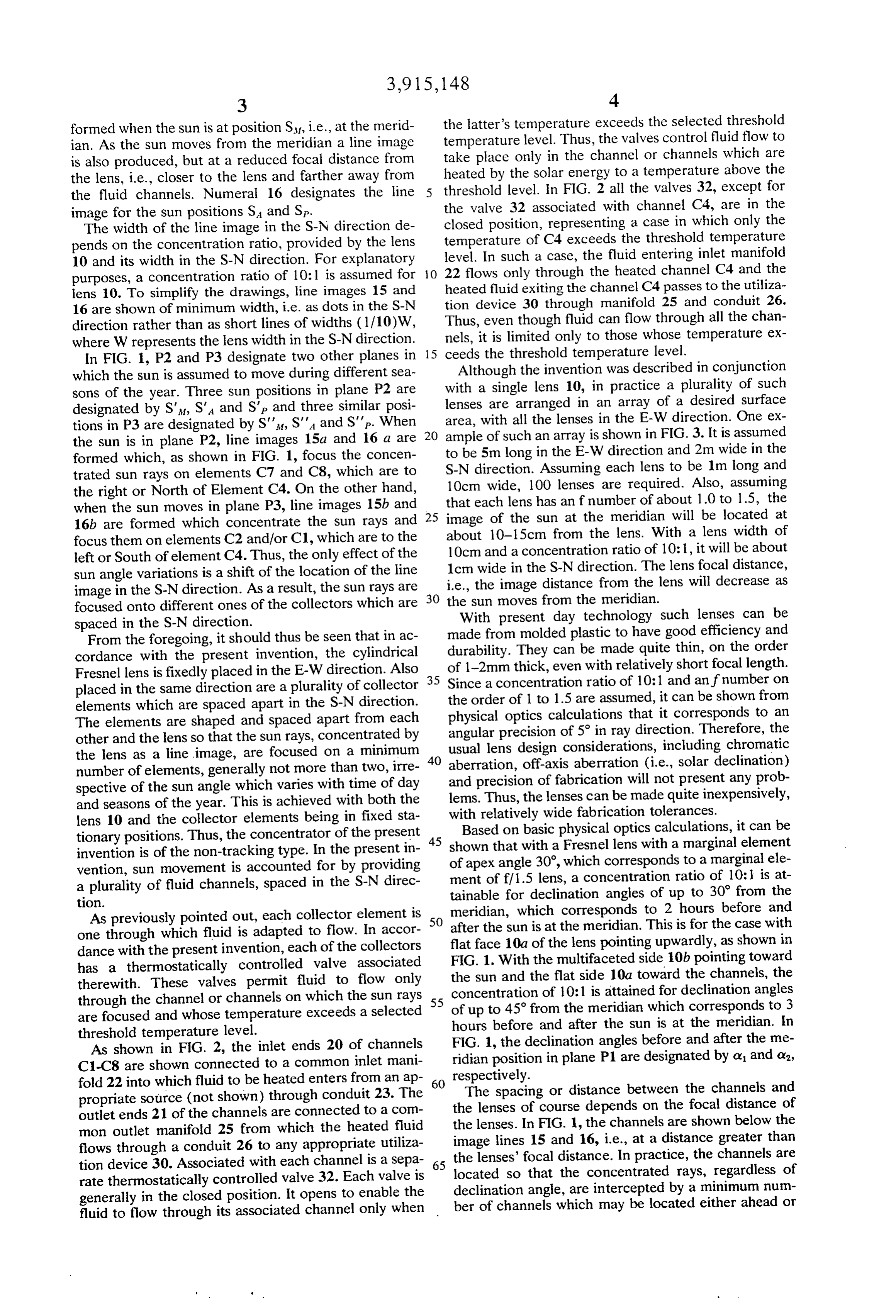
formed when the sun is at position St, i.e., at the merid the latter's temperature exceeds the selected threshold ian. As the sun moves from the meridian a line image temperature level. Thus, the valves control fluid flow to is also produced, but at a reduced focal distance from take place only in the channel or channels which are the lens, i.e., closer to the lens and farther away from heated by the solar energy to a temperature above the the fluid channels. Numeral 16 designates the line threshold level. In FIG. 2 all the valves 32, except for image for the sun positions S and Sp. the valve 32 associated with channel C4, are in the The width of the line image in the S-N direction de closed position, representing a case in which only the pends on the concentration ratio, provided by the lens temperature of C4 exceeds the threshold temperature level. In such a case, the fluid entering inlet manifold 10 and its width in the S-N direction. For explanatory O 22 flows only through the heated channel C4 and the purposes, a concentration ratio of 10:1 is assumed for lens 10. To simplify the drawings, line images 15 and heated fluid exiting the channel C4 passes to the utiliza 16 are shown of minimum width, i.e. as dots in the S-N tion device 30 through manifold 25 and conduit 26. direction rather than as short lines of widths (1/10)W, Thus, even though fluid can flow through all the chan where W represents the lens width in the S-N direction. 5 nels, it is limited only to those whose temperature ex In FIG. 1, P2 and P3 designate two other planes in ceeds the threshold temperature level. Although the invention was described in conjunction which the sun is assumed to move during different sea sons of the year. Three sun positions in plane P2 are with a single lens 10, in practice a plurality of such designated by S', S'A and SP and three similar posi lenses are arranged in an array of a desired surface tions in P3 are designated by S', S', and S'p. When 20 area, with all the lenses in the E-W direction. One ex the sun is in plane P2, line images 15a and 16 a are ample of such an array is shown in FIG. 3. It is assumed formed which, as shown in FIG. 1, focus the concen to be 5m long in the E-W direction and 2m wide in the trated sun rays on elements C7 and C8, which are to S-N direction. Assuming each lens to be 1m long and the right or North of Element C4. On the other hand, 10cmeach wide, 100 lenses are required. Also, assuming when the sun moves in plane P3, line images 15b and 25 that image of lens has an f number of about 1.0 to 1.5, the the sun at the meridian will be located at 16b are formed which concentrate the sun rays and focus them on elements C2 and/or C1, which are to the about 10-15cm from the lens. With a lens width of left or South of element C4. Thus, the only effect of the 1cm10cm and a concentration ratio of 10:1, it will be about wide in the S-N direction. The lens focal distance, sun angle variations is a shift of the location of the line i.e., the image distance from the lens will decrease as image in the S-N direction. As a result, the sun rays are 30 the sun moves focused onto different ones of the collectors which are from the meridian. spaced in the S-N direction. With present day technology such lenses can be From the foregoing, it should thus be seen that in ac made fromThey molded plastic to have good efficiency and cordance with the present invention, the cylindrical durability. can be made quite thin, on the order Fresnel lens is fixedly placed in the E-W direction. Also 35 Since a concentration with of 1-2mm thick, even ratio relatively short focal length.
of 10:1 and an if number on placed in the same direction are a plurality of collector elements which are spaced apart in the S-N direction. the order of 1 to 1.5 are assumed, it can be shown from The elements are shaped and spaced apart from each physical optics calculations that it corresponds to an angular precision of 5 in ray direction. Therefore, the other and the lens so that the sun rays, concentrated by usual lens design considerations, including chromatic the lens as a line image, are focused on a minimum 40 number of elements, generally not more than two, irre aberration, off-axis aberration (i.e., solar declination) spective of the sun angle which varies with time of day lems. Thus, theoflenses and precision fabrication will not present any prob can be made quite inexpensively, and seasons of the year. This is achieved with both the with relatively wide fabrication tolerances. lens 10 and the collector elements being in fixed sta Based on basic physical optics calculations, it can be tionary positions. Thus, the concentrator of the present 45 shown that with a Fresnel lens with a marginal element invention is of the non-tracking type. In the present in vention, sun movement is accounted for by providing of apex angle 30, which corresponds to a marginal ele ment of f/1.5 lens, a concentration ratio of 10:l is at a plurality of fluid channels, spaced in the S-N direc tainable for declination angles of up to 30 from the tion.
As previously pointed out, each collector element is 50 meridian, after the sun which corresponds to 2 hours before and is at the meridian. This is for the case with one through which fluid is adapted to flow. In accor flat face 10a of dance with the present invention, each of the collectors FIG. 1. With thethemultifaceted lens pointing upwardly, as shown in side 10b pointing toward has a thermostatically controlled valve associated the sun and the flat side 10a toward the channels, the therewith. These valves permit fluid to flow only concentration of 10:1 is attained for declination angles through the channel or channels on which the sun rays 55 of up to 45° from the meridian which corresponds are focused and whose temperature exceeds a selected hours before and after the sun is at the meridian.toIn3 threshold temperature level. FIG. 1, the declination angles before and after the me As shown in FIG. 2, the inlet ends 20 of channels ridian position in plane P1 are designated by ox and o, C1-C8 are shown connected to a common inlet mani fold 22 into which fluid to be heated enters from an ap 60 respectively.
propriate source (not shown) through conduit 23. The theThe spacing or distance between the channels and lenses of course depends on the focal distance of outlet ends 21 of the channels are connected to a com mon outlet manifold 25 from which the heated fluid the lenses. In FIG. 1, the channels are shown below the flows through a conduit 26 to any appropriate utiliza image lines 15 and 16, i.e., at a distance greater than tion device 30. Associated with each channel is a sepa 65 the lenses' focal distance. In practice, the channels are rate thermostatically controlled valve 32. Each valve is located so that the concentrated rays, regardless of generally in the closed position. It opens to enable the declination angle, are intercepted by a minimum num fluid to flow through its associated channel only when ber of channels which may be located either ahead or
Page 7
S 6 beyond the image plane, i.e., the plane where the image may be used to reduce heat losses and thereby maxi is formed. With an assumed image width of lcm the mize the amount of heat which is received by each tips of each channel should preferably be spaced apart channel to heat the fluid passing therethrough. not less and preferably more than 1cm. The tips of the The surfaces 13 of the channels which are exposable channels are designated in FIG. 1 by numerals 33. The to the concentrated sun rays should preferably be cov number of channels which need be associated with ered with an infrared (IR) selective coating in order to each lens depends on the width (in the S-N direction) reduce IR reradiation, and thereby increase the ther of each channel and the extent of the shift of the image mal energy absorbed by the channels from the concen in the S-N direction as the sun angle changes with the trated rays for delivery to the fluid flowing through the seasons of the year. 10 heated channel. Various IR selective coatings for such In Fig. 1, all the channels are shown with their tips 33 a purpose are available commercially. They include sil above the image plane of any of the image lines formed icon carbide and combinations of molybdenum and sili by the lens 10. Also, all the channels are shown with con oxides.
their tips in a plane parallel to the flat surface 10a of It should be appreciated that the working fluid need the lens and in addition the channels are shown of 15 not be limited to water. It can include ethylene glycol, equal widths, i.e., equal spacing between their tips 33. pressurized water or other organic compounds. The Such an arrangement is shown for explanatory pur utilization device 30 to which the heated fluid is sup poses only. In order to minimize the number of chan plied may be any system in which heated fluid is uti nels on which the concentrated rays focus or impinge, lized. For example, the heated fluid may be directed to an arrangement as shown in FIG. 4 may be employed. 20 heat exchangers to provide domestic or commercial As shown therein, the channels may be supported on a heating or hot water, or for effecting refrigerative cool curved rather than flat support member 12. Also, the ing or operating heat engines for electricity generation. tips 33 may be closer to the lens so that some of the line Since the ultimate use of the heated fluid is not part of images, such as 15, 15a and 15b are formed beyond the 25 this invention it will not be described in any detail. channels' tips. In FIG. 4, the images are shown as short oneAsvalve previously pointed out, each channel has at least 32 associated therewith, to control fluid to lines in the S-N direction rather than as points, as in
FIG. 1. As appreciated, the widths of these lines are flow through the channel only when its temperature ex 1/10 of the lens width for a concentration ratio of 10:1. ceeds a desired level. The valve may be one with a bi Also, the channels may be of variable widths. As metallic snap action element with two positions, one shown in FIG. 1, for the sun in either planes P2 and P3 stable when hot and the other when cold. Alternately, the concentrated rays are assumed to be absorbed by a valve which proportionately controls fluid rate as a function of temperature may be used to maintain the at least two channels, such as C1 and C2 for the sun in desired plane P3 and channels C7 and C8 for the sun in plane valve output temperature of the fluid. Also, each P2. If desired, the outer channels designated C. and C, 35 solar energybestriking may mounted to be influenced directly by the the outside of the channel surface in Fig. 4 may be wider than the width of the center as well as by the actual temperature of the fluid in the channel C, thereby reducing the number of channels heated channel.
receiving the concentrated rays when the sun is at other It can be shown that at 42°N latitude under clear sky than in a plane P1 perpendicular to the lens surface. conditions conversion efficiency of the order of about With the channel arrangement of FIG. 1, the maximum 40 60% is achievable with a lens with a transmission coef number of channels on which the concentrated rays are ficient g.9, a channel with an equivalent absorptivity focused may be limited to three even with channel o,9, and a concentration width of not less than the image width. With the chan ceived by the heat absorberfactor 14 y=10. The power re may be defined as P.
nel arrangement of FIG. 4, the maximum number may be reduced to two. It should also be pointed out that 45 and expressed
P = orgpinA,
the lens 10 needs to be placed with its flat surface 10a where p is the solar flux in wicm' and A is the area of in a horizontal tip. In practice, it may be tipped so that during the particular season when highest efficiency is the receiver facing the sun. In FIG. 3, A is assumed to be 10m = 10cm. The received power p is equal to desired, the sun would be moving in a perpendicular the power removed by the fluid, represented by Po, plus plane and its associated rays absorbed by preferably 50 the losses due to reradiation P, structural conduction one channel. P and convection P. That is,
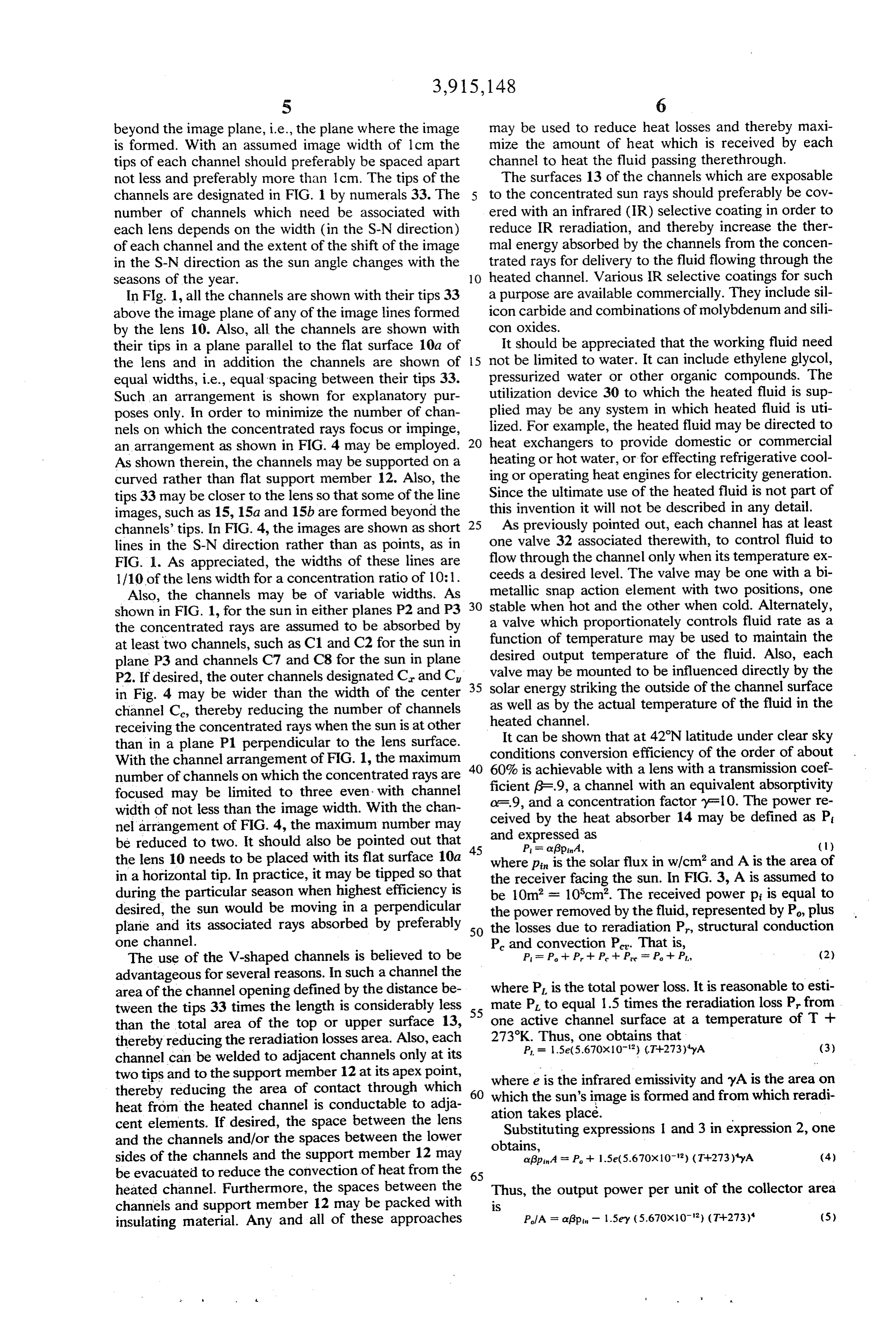
The use of the V-shaped channels is believed to be P = P -- P - P -- P = P + Pl, (2) advantageous for several reasons. In such a channel the area of the channel opening defined by the distance be where P is the total power loss. It is reasonable to esti tween the tips 33 times the length is considerably less 55 mate P to equal 1.5 times the reradiation loss P from than the total area of the top or upper surface 13, one active channel surface at a temperature of T - thereby reducing the reradiation losses area. Also, each 273K.P =Thus, one obtains that
channel can be welded to adjacent channels only at its two tips and to the support member 12 at its apex point, thereby reducing the area of contact through which 60 where e is the infrared emissivity and yA is the area on heat from the heated channel is conductable to adja ation takessun's which the image is formed and from which reradi place.
cent elements. If desired, the space between the lens Substituting expressions l and 3 in expression 2, one and the channels and/or the spaces between the lower obtains, sides of the channels and the support member 12 may agp4 = P + 1.5e(5.670x10') (T+273)A (4) be evacuated to reduce the convection of heat from the 65 heated channel. Furthermore, the spaces between the Thus, the output power per unit of the collector area channels and support member 12 may be packed with S insulating material. Any and all of these approaches P/A = app - 1.5ey (5.670x10') (T+273) (5)
Page 8
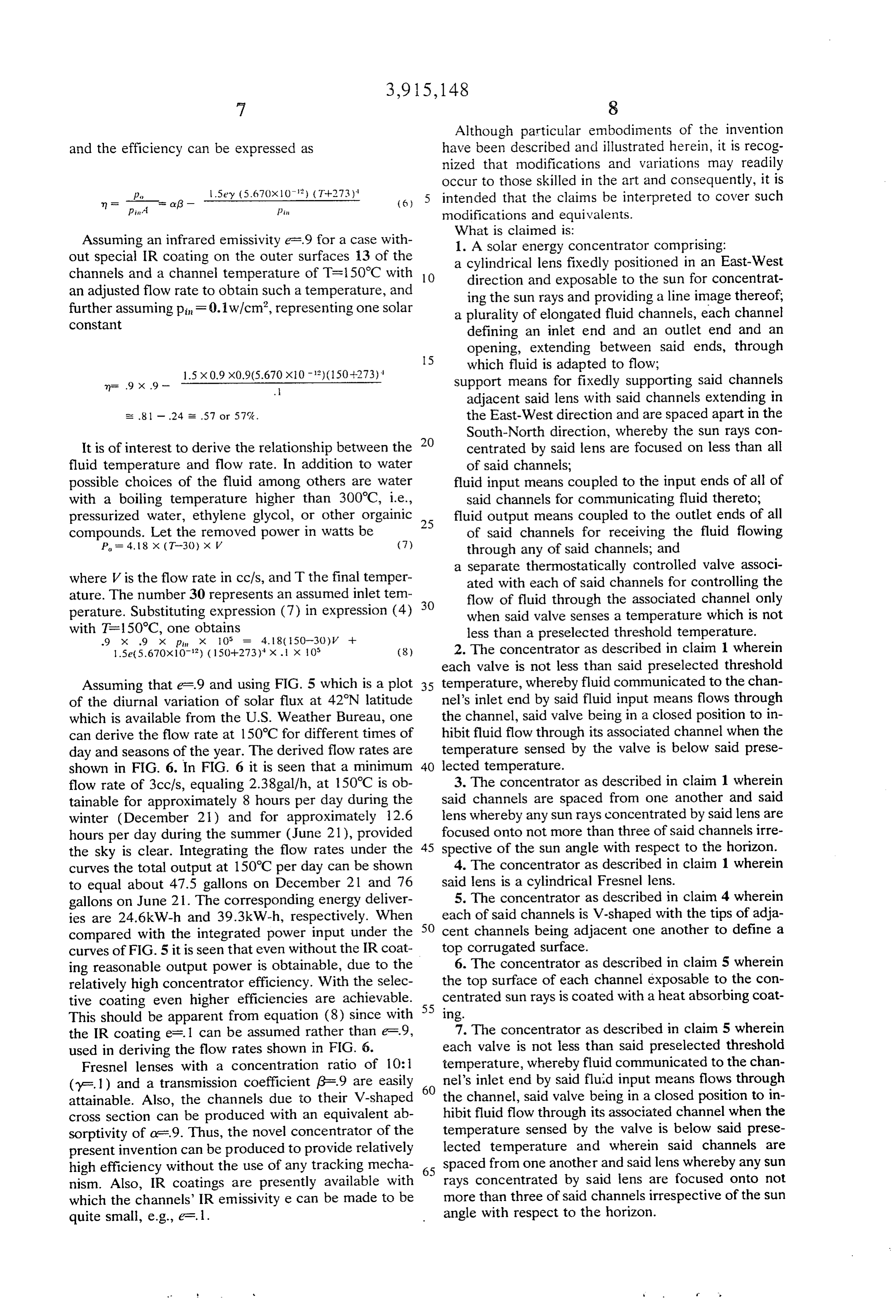
Although particular embodiments of the invention and the efficiency can be expressed as have been described and illustrated herein, it is recog nized that modifications and variations may readily occur to those skilled in the art and consequently, it is
(6) 5 intended that the claims be interpreted to cover such
Pin modifications and equivalents.
What is claimed is:
Assuming an infrared emissivity e.9 for a case with 1. A Solar energy concentrator comprising: out special IR coating on the outer surfaces 13 of the a cylindrical lens fixedly positioned in an East-West channels and a channel temperature of T=150°C with 10 direction and exposable to the sun for concentrat an adjusted flow rate to obtain such a temperature, and ing the sun rays and providing a line image thereof, further assuming pin-F 0.1 W/cm, representing one solar a plurality of elongated fluid channels, each channel COnStant defining an inlet end and an outlet end and an opening, extending between said ends, through 15 which fluid is adapted to flow;
1.5 x 0.9 x0.9(5.670 x0 - 12) (150-273) 4 support means for fixedly supporting said channels
adjacent said lens with said channels extending in s: .81 - .24 E. 57 or 57%. the East-West direction and are spaced apart in the South-North direction, whereby the sun rays con
It is of interest to derive the relationship between the 20 centrated by said lens are focused on less than all fluid temperature and flow rate. In addition to water of said channels;
possible choices of the fluid among others are water fluid input means coupled to the input ends of all of with a boiling temperature higher than 300°C, i.e., said channels for communicating fluid thereto; pressurized water, ethylene glycol, or other orgainic 25 fluid output means coupled to the outlet ends of all compounds. Let the removed power in watts be of said channels for receiving the fluid flowing P = 4, 18 x (T-30) x V (7) through any of said channels; and a separate thermostatically controlled valve associ where V is the flow rate in cc/s, and T the final temper ated with each of said channels for controlling the ature. The number 30 represents an assumed inlet tem 30 flow of fluid through the associated channel only perature. Substituting expression (7) in expression (4) when said valve senses a temperature which is not with T-150°C, one obtains less than a preselected threshold temperature. .9 x 9 X pin X 10° 4.18 (50-30)V -- 2. The concentrator as described in claim 1 wherein 1.5e(5,670x10-12) (150+273) x . x 105 (8) each valve is not less than said preselected threshold
Assuming that e-.9 and using FIG. 5 which is a plot 35 temperature, whereby fluid communicated to the chan of the diurnal variation of solar flux at 42N latitude nel's inlet end by said fluid input means flows through which is available from the U.S. Weather Bureau, one the channel, said valve being in a closed position to in can derive the flow rate at 150°C for different times of hibit fluid flow through its associated channel when the day and seasons of the year. The derived flow rates are temperature sensed by the valve is below said prese shown in FIG. 6. In FIG. 6 it is seen that a minimum 40 lected temperature.
flow rate of 3ccfs, equaling 2.38gal/h, at 150°C is ob 3. The concentrator as described in claim 1 wherein tainable for approximately 8 hours per day during the said channels are spaced from one another and said winter (December 21) and for approximately 12.6 lens whereby any sun rays concentrated by said lens are hours per day during the summer (June 21), provided focused onto not more than three of said channels irre the sky is clear. Integrating the flow rates under the 45 spective of the sun angle with respect to the horizon. curves the total output at 150°C per day can be shown 4. The concentrator as described in claim 1 wherein to equal about 47.5 gallons on December 21 and 76 said lens is a cylindrical Fresnel lens. gallons on June 21. The corresponding energy deliver 5. The concentrator as described in claim 4 wherein ies are 24.6kW-h and 39.3kW-h, respectively. When 50 each of said channels is V-shaped with the tips of adja compared with the integrated power input under the cent channels being adjacent one another to define a curves of FIG. 5 it is seen that even without the IR coat top6. corrugated surface.
The concentrator as described in claim 5 wherein ing reasonable output power is obtainable, due to the relatively high concentrator efficiency. With the selec the top surface of each channel exposable to the con tive coating even higher efficiencies are achievable. 55 centrated sun rays is coated with a heat absorbing coat This should be apparent from equation (8) since with ing.
the IR coating e=. 1 can be assumed rather than e-F.9, 7. The concentrator as described in claim 5 wherein used in deriving the flow rates shown in FIG. 6. each valve is not less than said preselected threshold Fresnel lenses with a concentration ratio of 10: 1 temperature, whereby fluid communicated to the chan (y=. 1) and a transmission coefficient g-9 are easily 60 nel's inlet end by said fluid input means flows through attainable. Also, the channels due to their V-shaped the channel, said valve being in a closed position to in cross section can be produced with an equivalent ab hibit fluid flow through its associated channel when the sorptivity of a .9. Thus, the novel concentrator of the temperature sensed by the valve is below said prese present invention can be produced to provide relatively lected temperature and wherein said channels are high efficiency without the use of any tracking mecha 65 spaced from one another and said lens whereby any sun nism. Also, IR coatings are presently available with rays concentrated by said lens are focused onto not which the channels' IR emissivity e can be made to be more than three of said channels irrespective of the sun quite small, e.g., e.l. angle with respect to the horizon.
Page 9
8. The concentrator as described in claim 1 including closed position to inhibit fluid flow through its associ a plurality of cylindrical lenses arranged in a rectangu ated channel when the temperature sensed by the valve lar array of selected surface area with all the lenses is below said preselected temperature. fixedly positioned in the East-West direction, with said 9. The concentrator as described in claim 8 wherein channels disposed below said lenses in the East-West each of said lenses is a cylindrical Fresnel lens. direction and spaced apart in the South-North direc 10. The concentrator as described in claim 9 wherein tion and wherein each valve is not less than said prese each of said channels is V-shaped with the tips of adja lected threshold temperature, whereby fluid communi cent channels being adjacent one another to define a cated to the channel's inlet end by said fluid input top corrugated surface.ck xk :k k >k means flows through the channel, said valve being in a 10
Provenance
- Collection
- Cited prior art
- Original PDF
- patentimages.storage.googleapis.com →
- Filed
- 1974-11-22
- Pages
- 9
- Method
- pdftotext (the PDF's own text layer) + pdftoppm 300dpi page scans
- Source
- Google Patents bibliographic record
- Granted
- 1975-10-28
- Inventors
- James C Administrator Fletcher; Katsunori Shimada
- Transcribed from
- patentimages.storage.googleapis.com →