patent · US4103673
Non-tracking solar energy concentrator
1 August 1978
Page 1 — bibliographic record
350 a 4,52 SR
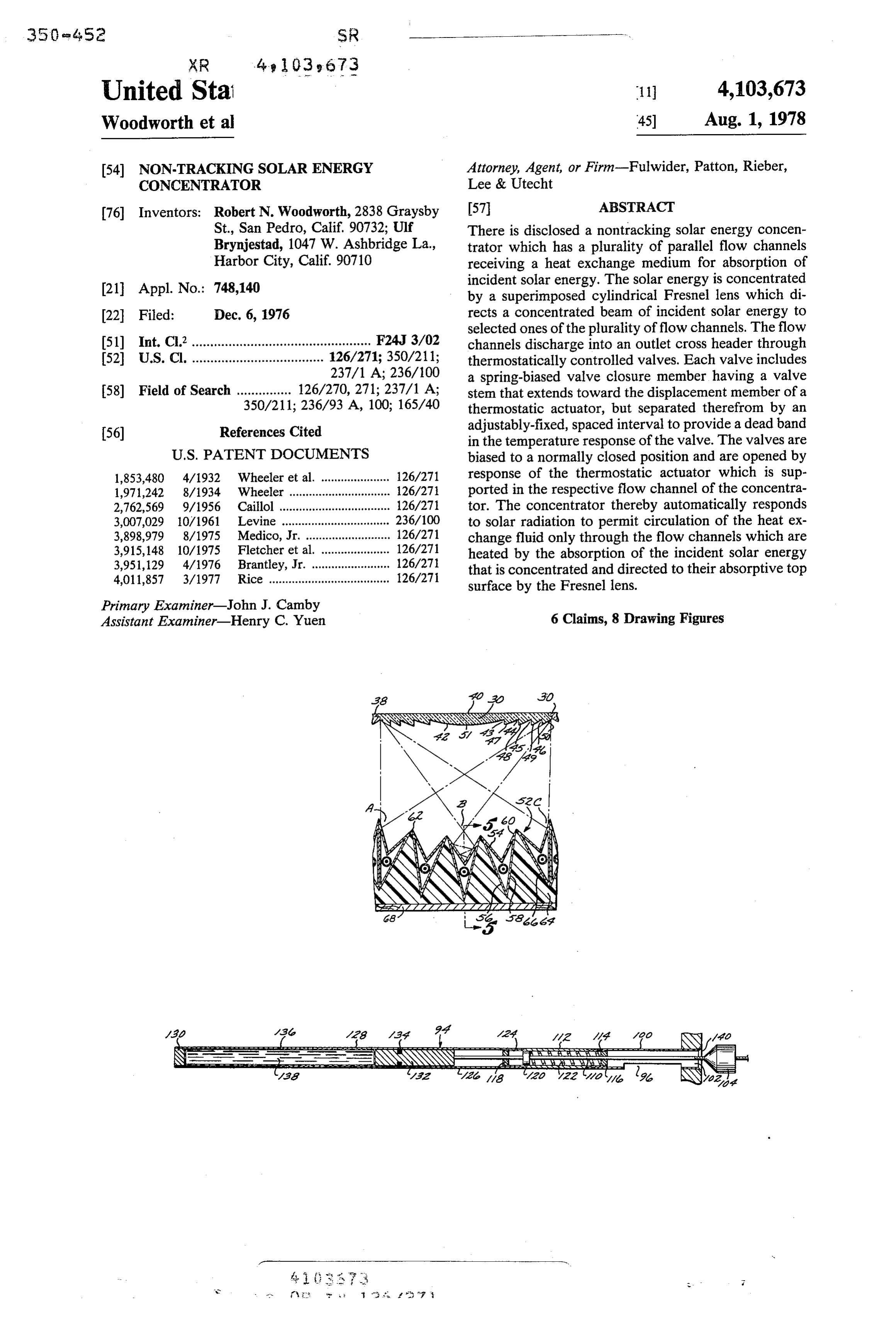
United Stal 11 4,103,673 Woodworth et a 45) Aug. 1, 1978 (54) NON-TRACKING SOLAR ENERGY Attorney, Agent, or Firm-Fulwider, Patton, Rieber, CONCENTRATOR Lee & Utecht 76 Inventors: Robert N. Woodworth, 2838 Graysby 57 ABSTRACT St., San Pedro, Calif. 90732; Ulf There is disclosed a nontracking solar energy concen Brynjestad, 1047 W. Ashbridge La., trator which has a plurality of parallel flow channels Harbor City, Calif. 90710 receiving a heat exchange medium for absorption of (21) Appl. No.: 748,140 incident solar energy. The solar energy is concentrated by a superimposed cylindrical Fresnel lens which di (22 Filed: Dec. 6, 1976 rects a concentrated beam of incident solar energy to selected ones of the plurality of flow channels. The flow 51) Int. C.’................................................. F24J 3/02 channels discharge into an outlet cross header through 52 U.S. Cl. .................................... 126/271; 350/211; thermostatically controlled valves. Each valve includes 237/1 A; 236/100 a spring-biased valve closure member having a valve 58) Field of Search ............... 126/270, 271; 237/1 A; stem that extends toward the displacement member of a 350/211; 236/93 A, 100; 165/40 thermostatic actuator, but separated therefrom by an 56) References Cited adjustably-fixed, spaced interval to provide a dead band in the temperature response of the valve. The valves are
1,853,480 4/1932. Wheeler et al. ..................... 126/271 response of the thermostatic actuator which is sup 1,971,242 8/1934 Wheeler ......... ... 126/27 ported in the respective flow channel of the concentra 2,762,569 9/1956 Caillol ........ ... 126/27 tor. The concentrator thereby automatically responds 3,007,029 10/1961 Levine ........... ... 236/100 to solar radiation to permit circulation of the heat ex 3,898,979 8/1975 Medico, Jr. ........ ... 126/271 change fluid only through the flow channels which are 3,915, 148 10/1975 Fletcher et al. ... ... 126/271 heated by the absorption of the incident solar energy 3,951,129 4/1976 Brantley, Jr. ...... ... 126/27 that is concentrated and directed to their absorptive top 4,011,857 3/1977 Rice ..................................... 126/271 surface by the Fresnel lens. Primary Examiner-John J. Camby
Assistant Examiner-Henry C. Yuen 6 Claims, 8 Drawing Figures
Maa /30 /23 Maf 22 a? Mao
Page 2
Drawing sheet — no readable text.
Page 3
actuator suspended within the flow channel and me
NON-TRACKING SOLAR ENERGY chanically coupled to the closure member of the valve CONCENTRATOR with adjustable means to permit selection of the circula BACKGROUND OF THE INVENTION tion temperature of the heat exchange medium. The preferred valve construction is a coaxial assembly of a 1. Field of Invention plurality of tubular members including a valve body, This invention relates to a solar energy concentrator spring housing and thermostatic actuator to provide an and, in particular, to a solar energy concentrator of the elongated tubular assembly which is supported by the non-tracking type having temperature responsive apertured header wall and projects into the flow chan means for controlling the flow of heat exchange fluid 10 nel. The valve body has an aperture in its sidewall to therethrough. provide an inlet port and its open end is secured to the 2. Brief Statement of the Prior Art: header wall with a beveled lip to provide a tapered A number of designs have been developed for solar valve seat for the valve closure member. The latter is a energy concentrators with the objective of focusing or plug having a generally conical seating surface and a concentrating incident solar energy onto a flow channel 15 central, internally threaded aperture which receives a of lesser surface area. Radiant energy concentrating threaded valve stem. The valve stem is received within devices such as optical lens, mirrored reflectors and the the spring housing, passing through a central aperture like have been suggested for this purpose. Concentra of a spring retainer, and fixedly carries a second spring tion of the incident solar energy is desirable to obtain retainer. A helical coil compression spring is captured higher working temperatures of the heat exchange fluid 20 between the spring retainers to bias the closure member than possible with flat plate collectors, thereby permit into a sealing position against the valve seat. The ther ting more efficient power extraction. Most solar con mostatic actuator is distally carried by the spring hous centrators are of the tracking variety in which a flow ing and has a displacement member responsive to a channel for the heat exchange fluid is supported at the thermally expansive material within the actuator to focus of a lens or reflector and the assembly is mechani 25 move into abutment with the valve stem and move the cally actuated to track the incident angle of sunlight valve closure member into an open position against the which continually varies with the season of the year and bias of the spring. The spacing between the end of the time of day. valve stem and the displacement member is fixedly A solar concentrator of the non-tracking type is dis adjustable to provide a deadband in the response of the closed in U.S. Pat. No. 3,915,148. In this concentrator, 30 valve, thereby providing a fixed adjustability in the a plurality of parallel flow channels are supported be operating temperature of the concentrator. neath a cylindrical Fresnel lens which concentrates the BRIEF DESCRIPTION OF THE DRAWINGS incident solar energy into a narrow beam of concen trated lightenergy and directs the beam to selected ones The invention will be described by the illustrated, of the subjacent flow channels. The beam of concen 35 preferred embodiment of which:
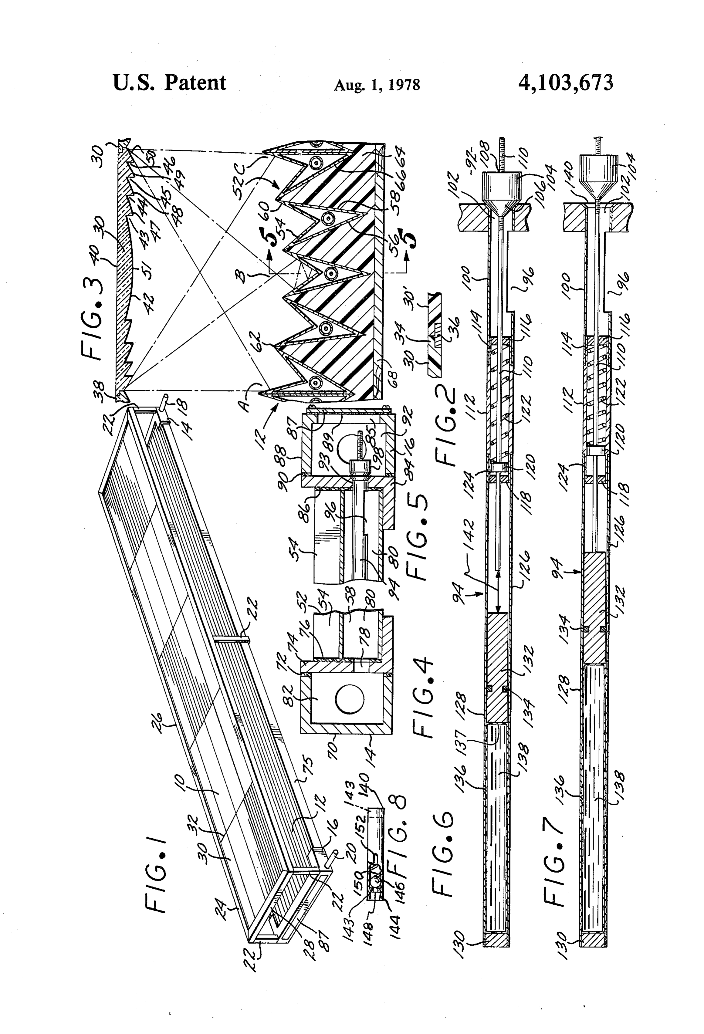
trated light energy shifts between adjacent flow chan FIG. 1 is a perspective view of the solar concentrator nels in response to the change in the incident angle of of the invention;
sunlight. FIG. 2 is a sectional view of a lens element support; While the aforementioned patent suggests a construc FIG. 3 is a cross-sectional end view of a portion of tion of a solar energy concentrator which eliminates the the concentrator;
complex mechanism necessary for tracking the continu FIGS. 4 and 5 are sectional elevational views of the ally varying incident angle of sunlight, it creates an inlet and outlet portions, respectively of the concentra other unsolved problem. This latter problem is the de tor;
sign of suitable valve means that can be mounted in each FIGS. 6 and 7 are sectional views of the thermostatic of the flow channels to permit flow through only the 45 valve used in the invention; and flow channel which receives the beam of concentrated FIG. 8 illustrates a useful check valve construction. light energy. For efficient operation of the solar energy DESCRIPTION OF PREFERRED concentrator, it is essential that the valves employed in EMBODIMENTS the flow channels tightly seal the flow channels which are not receptive to the beam of concentrated solar 50 Referring now to FIG. 1, the solar concentrator com energy. It is also necessary that the valves respond prises a lens panel 10 and a subjacent heat exchange quickly to temperature changes of the heat exchange flow panel 12. The flow panel 12 is formed of a plurality fluid as the respective flow channel is exposed to the of extruded metal channel units in side-by-side align beam of concentrated light energy. ment and extending the full length of the panel. The 55 flow panel assembly distally bears an inlet cross header
BRIEF STATEMENT OF THE INVENTION
14 and an outlet cross header 16 having nozzles 18 and
This invention comprises a solar energy concentrator 20 for connection to conduits communicating with a of the non-tracking type having a plurality of heat ex source of a heat exchange fluid and with the energy change flow channels supported beneath a Fresnel lens recover facilities employed with the solar energy con which concentrates the incident solar energy and di 60 centrator. A plurality of vertical posts 22 are provided rects a concentrated light beam to selected ones of the at each corner of the concentrator and along the length flow channels. The flow channels of the concentrator thereof as necessary to support the lens panel 10. A are distally secured to cross headers which provide frame 24 formed of longitudinal spars 26 and lateral communicating apertures to each of the flow channels. spars 28 is carried on the vertical posts 22. A plurality of The apertures of the outlet cross header are provided 65 extruded plastic lens elements 30 are supported in the with the thermostatically actuated valves of the inven flat plane defined by frame 24. The lens elements are tion. Each flow channel is sealed, at its outlet port, by joined, end-to-end by support bars which span across normally closed valve means having a thermostatic the frame, between the longitudinal spars 26 at each of
Page 4
the joint lines 32. FIG. 2 illustrates this joint where the The opposite end of the channel unit 54 is scalably abuting ends of the lens elements 30 and 35 have a flat secured against the upright wall of angle member 84 by lip 34 which laps over the cross bar 36 that extends angle gasket 86. The outboard face of this upright wall of between the longitudinal spars of the frame. member 84 is sealably engaged by channel mem Referring now to FIG. 3, the individual lens elements 5 ber 88 with gasket 90 to define an outlet header cham 30 of the lens panel 10 are joined to adjacent elements in ber 92. The upright wall of angle member 84 also bears a longitudinal joint 38 using a half lap joint wherein the a plurality of apertures, one each positioned for commu adjoining panels have opposing lips. FIG.3 also shows nication with the channel fluid passageway 80. Each of the cross-sectional lens configuration of the lens ele the apertures receives a normally closed valve 94 hav ments 30. Each element has a flat upper surface 40 and 10 ing an inlet port 96 which communicates through the a multifacited undersurface 42 which has a plurality of ber 92body valve to its open end which discharges into cham stepped zones defined by parallel grooves 43–46 which memberand98.which is sealably closed by the valve closure form facets 47-50, each of which has a cylindrical un Referring now to FIGS. 6 and 7, the valves 94 will be dersurface and each of which is capable of serving as a described in greater detail. As there illustrated, each refractory lens for bending light and focusing the light valve is formed energy into a narrow beam. The central portion 51 of aperture means 96byinaa tubular sidewall valve body 100 having to serve as a fluid inlet each lens element also has a cylindrical undersurface to port and an open end 102 discharging into chamber 92 function as a refractory lens. As well known in Fresnel and serving as an outlet port. Each valve has a valve lens construction, the width of the facets or zones of 0 closure member 104, a generally plug-shaped member each lens element progressively decreases in the lateral 2 having a conical inboard end 106 and a central, inter directions. nally threaded aperture 108. Aperture 108 thrcadably The flow channel plate 12 is defined by a plurality of flow channel units 52. Each unit comprises a plurality of receives a distal portion of valve stem 110. The valve body 100 distally bears a tubular spring
V-shaped flow channels 54 which are defined by two, 25 housing 112 which has an end 114 of a slightly reduced inclined and intersecting sidewalls 56 and 58 and a top diameter to be received within the inboard end of valve wall 60 which has a V-shape. A plurality of the channel units 52 are aligned, side-by-side, to provide the flow body 100. The spring housing has end plates 116 and 118 with central apertures for receiving valve stem 110.
channel plate 12 of the concentrator. The valve stem 110 has a piston 120 fixedly secured The lens elements 30 are molded plastic elements formed of plastics having suitable optical properties, thereto and a helical coil compression spring 122 is biased between end plate 116 and piston 120 to bias the e.g., acrylic, polycarbonate resins and the like. The lens valve closure member 104 into its closed position, as are provided with optical finishes as can be achieved shown in FIG. 6.
using conventional plastics molding technology. The The inboard end of spring housing 112 is of slightly flow channel units 52 can be formed of a single metal is reduced diameter to receive the end of the thermal extrusion, e.g., an aluminum extrusion. Preferably, the actuator 126. The thermal actuator 126 is formed of a edges of adjacent flow channels are secured together by tubular member 128 having an end plate 130 and a dis a joint 62 which presents a minimal area, e.g., a line placeable member 132, e.g., a piston, slidably mounted joint. therein. The displacement member 132 can have a pe The units 52 are supported on a suitable insulating 40 ripheral groove for receiving a sealing means such as material 64 having a top surface with a contour of V O-ring 134. The chamber 136 behind displaceable mem grooves 66 to receive the V-shaped flow channels. The ber 132 is filled with a thermally expansive material 138, insulating material can be any suitable thermally insulat e.g., oil, water, wax and the like. Preferably, the ther ing solid closed cell cellular plastic foams such as poly mally expansive liquid 138 is contained within a sack styrene foam, polyurethene foam and the like are pre- 45 137 of an elastomeric material, e.g., rubber, Neopreme ferred. The V-grooves are preferably disposed on the and the like, thereby insuring against leakage of this top surface of the insulation 64 on a common radius, liquid.
matching the radius of curvature of the cylindrical The valve 94 is illustrated in FIG. 7 in its open posi Fresnel lens elements 30, thereby insuring that the indi tion in which the valve closure member 104 has moved vidual top surfaces 54 of the respective flow channels 50 away from the tapered valve seat 140 which is formed are equidistant from the Fresnel lens elements. The about the open end 102 of the valve body 100. The thermally insulating foam solid can be supported on a valve closure member 104 is lifted from its closed posi suitable backing plate 68. tion shown in FIG. 6 to the open position of FIG. 7 by FIG. 4 is a partial sectional view through the inlet the expansion of the thermally expansive liquid 138 cross header 14. This header is formed by channel 70 55 which moves the displaceable member 132 sufficiently which is compressed against a sealing gasket 72 and the to abut this member against the inboard end of valve outboard face of angle member 74. The angle member stem 110 and lift the valve closure member. 74 has an upright wall which is sealably secured against The valves 94 employed in the invention are pro the open end of the flow channel unit 52 by gasket 76. vided with adjustment means whereby the temperature The upright wall of angle member 4 has a plurality of 60 of response, i.e., opening of the valves is fixedly adjust apertures 78 which communicate from the chamber 82 able. This is accomplished by providing an adjustable, to the interior passageway 80 of each flow channel. spaced interval 142 (see FIG. 6) between the inboard Suitable check valve means can, if desired, be em end of the valve stem 110 and the abuting end of dis ployed in apertures 78 to insure that the heat exchange placement member 132. This spacing provides a dead fluid flow in the assembly is from chamber 82 to the 65 band in the thermal response of the valve, requiring that respective flow channel passageway 80, thereby pre the liquid 138 be raised to a preselected or threshold venting any possible back mixing of fluid during its temperature before any actuation of the valve closure heating in the channel passageway 80. member occurs. The adjustability in the spaced interval
Page 5
142 is accomplished by the threaded engagement of invention be defined by the means, and their obvious valve stem 110 with the valve closure member 104. The equivalents, set forth in the following claims. rotation of the valve closure member on valve stem 110 What is claimed is:
causes retraction or extension of the valve stem in the 1. A solar energy concentrator comprising: assembly, increasing or decreasing the magnitude of the a lens element to receive incident solar energy and dead band, i.e., space 142. focus the received solar energy into a narrow, The entire assembly of inlet and outlet headers, angle concentrated beam;
members 74 and 84 and flow channel units is retained in a plurality of parallel flow channels having inlet and the base frame which includes longitudinal frame mem outlet ends and in side-by-side relationhsip beneath bers 75 (See FIG. 1). Tie rods or bolts can be provided 10 said lens element and oriented with respect thereto to compress the assembly longitudinally, thereby for reception of said concentrated beam of solar tightly sealing gaskets 72,76, 86 and 90. Access to outlet energy on respective ones of said flow channels; header 16 is provided by an opening 85 in the front face inlet cross header means in open communication to of the header which is covered by removable plate 87 each of said flow channels to supply a heat ex and sealed by gasket 89, shown in FIGS. 1 and 5. 15 change fluid to the inlet of said flow channels;
FIG. 8 illustrates a suitable check valve which can be mounted in aperture 78. The valve has a tubular housing outlet cross header means in communciation through 140 having opposite end plates 143. The end 144 of outlet valve port means with each of said flow housing 140 is mounted in aperture 78 and its respective channels to remove heated heat exchange fluid end plate has an aperture 148. A ball 146 is seated in 20 from the other said flow channels; aperture 148 by compression spring 150 and serves as a valve means in each of said flow channels including a valve closure member. Fluid flow through the valve is tubular valve body having an open end received in unidirectional; through aperture 148, past ball 146 and said outlet cross header and positioned within its out through slots 152 on opposite sides of housing 140. respective flow channel with inlet port means in In operation, the solar concentrator is placed with its 25 the wall of said tubular member and valve seat longitudinal axis in a generally east-west alignment to means extending about the open end of each of said receive incident sunlight on the flat lens panel 10. The outlet port means, a valve closure member carried Fresnel lens elements 30 are effective in focusing the on a valve stem for movement between closed and received sunlight into a narrow beam such as identified open registration with said valve seat means; by letters A, B and C in FIG. 3. The narrow band of 30 a coaxial tubular spring housing received on the in concentrated light energy falls on one of the individual board end of said valve body and bearing an end flow channels. The channels are flooded with the heat plate and receiving said valve stem with the latter exchange fluid since the inlet apertures 78 are normally fixedly carrying a piston; open to permit free flow into the flow channels but are a helical coil spring received between said end plat closed at the outlet apertures 93 by their respective 35 and piston;
valves 94. When the concentrated light energy falls on thermostatic actuator means supported within its the receptive surface 54 of one of the flow channels, the respective flow channel and including a displace heat exchange fluid in the channel is rapidly heated, able member moveably responsive to temperature heating the thermally expansive liquid 138 within the changes experienced by said thermostatic actuator thermal actuator of the valve 94. When the displaceable 40 and moveable into an abutment position with the member 132 is moved in response to the expansion of received end of said valve stem to effect relative the liquid 138 a sufficient degree to traverse the spaced movement of said closure member; and interval 142 and abut against valve stem 110, any con adjustment means whereby the spacing between said tinued heating lifts the valve closure member 104 from displaceable member and the received end of said the valve seat 140 of the valve 94, permitting the hot 45 valve stem is adjustably variable to provide a con fluid to escape into the chamber 92 of the outlet cross trollable deadband in response of said valve closure header. The hot fluid is removed through nozzle 20 and member to temperature changes of said thermo appropriate conduits to heat recovery stages for the static actuator.
development of power, heat, or cooling therefrom. A 2. The solar concentrator of claim 1 wherein said suitable pump is used to return cold heat exchange fluid 50 flow channels have inclined, intersecting sidewalls and to inlet header 14, establishing circulation through the a V-shaped top surface for reception of said concen concentrator. trated beam of solar energy.
A typical solar concentrator can be constructed hav 3. The solar concentrator of claim 1 wherein said ing the features shown in the figures with an area of flow channels are mounted on a thermally insulating approximately 10 square meters. The overall dimen 55 support.
sions of this concentrator is 2 by 5 meters using a total 4. The solar concentrator of claim 1 wherein said lens of 100 lens elements 30 supported over 20, side-by-side element is a cylindrical Fresnel lens. disposed, flow channel units 52 which provide a total of 5. The solar concentrator of claim 1 wherein said 100 flow channels spanning the two meter width of the resilient means comprises a helical coil spring biased concentrator. At an incident solar flux of 1 Langley the 60 between a fixed position spring retainer secured to said outlet temperature of the heat exchange liquid is about valve body and a piston fixedly secured to said valve 150 C at a flow rate of about 38 cm/sec. A suitable stem.
heat exchange fluid for use in this application is a ortho 6. The solar concentrator of claim 1 wherein said dichlorobenzene (Dowtherm E). thermostatic actuator comprises a tubular cylinder and The invention has been described with reference to 65 piston motor actuator coaxially carried on the inboard the illustrated and presently preferred embodiment. It is end of said spring retainer and receiving the inboard not intended that the invention be unduly limited by the end of said valve stem.
illustrated embodiment. Instead, it is intended that the
Provenance
- Collection
- Cited prior art
- Original PDF
- patentimages.storage.googleapis.com →
- Filed
- 1976-12-06
- Pages
- 5
- Method
- pdftotext (the PDF's own text layer) + pdftoppm 300dpi page scans
- Source
- Google Patents bibliographic record
- Granted
- 1978-08-01
- Inventors
- Robert N. Woodworth; Ulf Brynjestad
- Transcribed from
- patentimages.storage.googleapis.com →