patent · US1676464
Headlight
10 July 1928
Page 1
Drawing sheet — no readable text.
Page 2
Patented July 10, 1928. 1,676,464
WALTER D'ABCY RYAN, OF SCHENECTADY, NEw Yor.
- BEADGEE,
Application filed September 2, 1924. Serial No. 735,409.
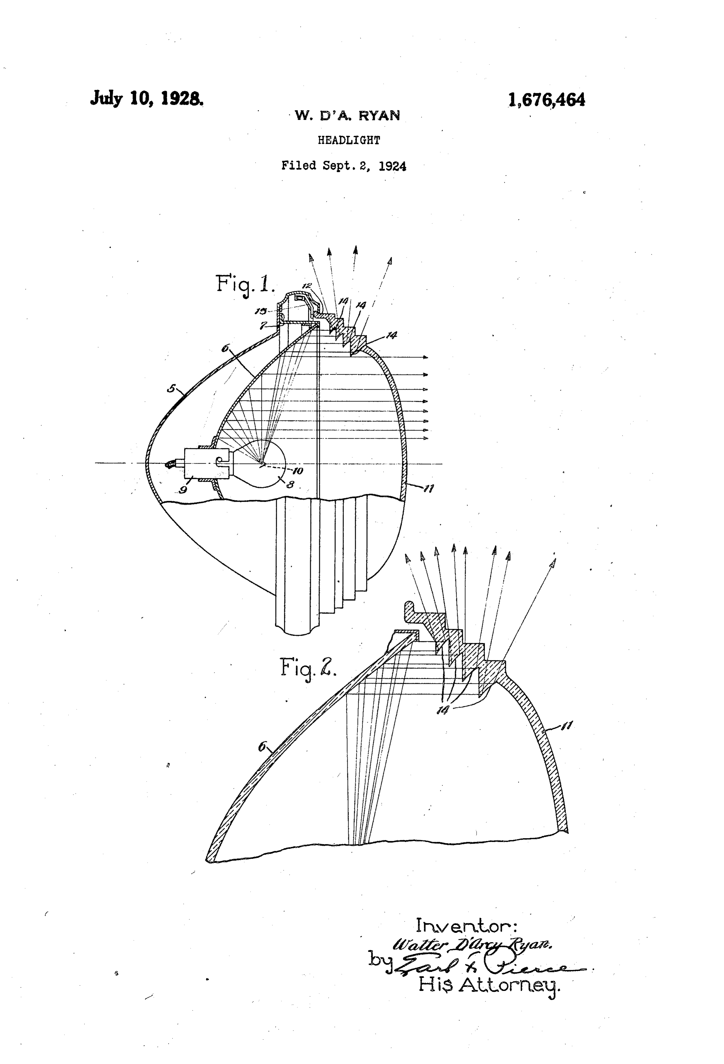
My invention relates to improvements in portions of the reflector 6 and deflect it. headlights, and is particularly concerned laterally and to the rear of the headlight. 55 with improvements in headlights for use on From an inspection of the drawings it will automobiles and other automotive vehicles. be seen that one face of each of the prisms 14 The objects of my present invention are: is disposed substantially at right angles to First, to provide a headlight comprising means for adequately illuminating the road the face axis of the reflector, whereas the other 6 is disposed at an acute angle to the axis.
way in advance of the vehicle carrying the It will also be noted that the angle between headlight; the two faces of each prism is larger in each Second, to provide a headlight compris succeeding prism. The outer face of the ing means for illuminating the sides of the lens, Opposite the prisms 14, is stepped, as 65 road immediately adjacent the vehicle, so as shown in Figure 2, so as to provide substan to enable the operator to perceive the mile tially non-deflecting surfaces through which posts and other signs at the sides of the the laterally deflected rays of light may pass. 5 road: By the arrangement described above, I Third, to provide a headlight, such as de provide a headlight in which practically all scribed, including means for illuminating the of the light reflected from the central por to sides of the road to the rear of the headlight, tion of the reflector is utilized for illuminat so as to illuminate a road into which the ing the roadway ahead of the vehicle, and 20 operator is turning; and the light reflected from the margin of the re Fourth, to provide a headlight of the char-. flector is used for illuminating those por 75 acter described that is simple in construc-‘tions of the sides of the road immediately ad tion and economical to manufacture. jacent the vehicle. The directions of the Other objects of my invention will appear forwardly projected rays and the laterally 25 as this description progresses, reference be and rearwardly projecting rays are clearly ing had to the accompanying drawings, in indicated by the arrows in the drawings. which By placing the annular prisms so as to 8 Figure 1 is a side elevation, partially in deflect the rays of light reflected from the section; and marginal portions of the reflector, I elimi 30 Figure 2 is a sectional detail on an en nate the source of glare in headlights of con larged scale.
Referring to the drawings, my improved that ventional design usually and make produces glare use for of headlight comprises a suitable casing or the roadway immediately ahead of the that light illuminating s housing 5, containing and supporting a re vehicle and for illuminating the sides of the flector 6 that may be either ellipsoidal, hy road immediately adjacent the vehicle. perboloidal or paraboloidal, as may be de While I have described the details of con sired. This reflector is supported by a ring struction of the preferred embodiment of 90 7 carried by the housing 5. An electric lamp my invention, it is to be clearly under 8 is carried by a suitable socket 9, Supported stood that my invention is not limited to 4. in the bottom of the reflector 6. The fila these details, but is capable of other adap ment 10 of the lamp 8 is preferably posi tations and modifications within the scope of tioned at or near the focal point of the re the appended claim. 95 flector 6. A bowl-shaped outwardly convex Having thus described my invention, lens 11 is positioned in front of the reflector what I claim is:
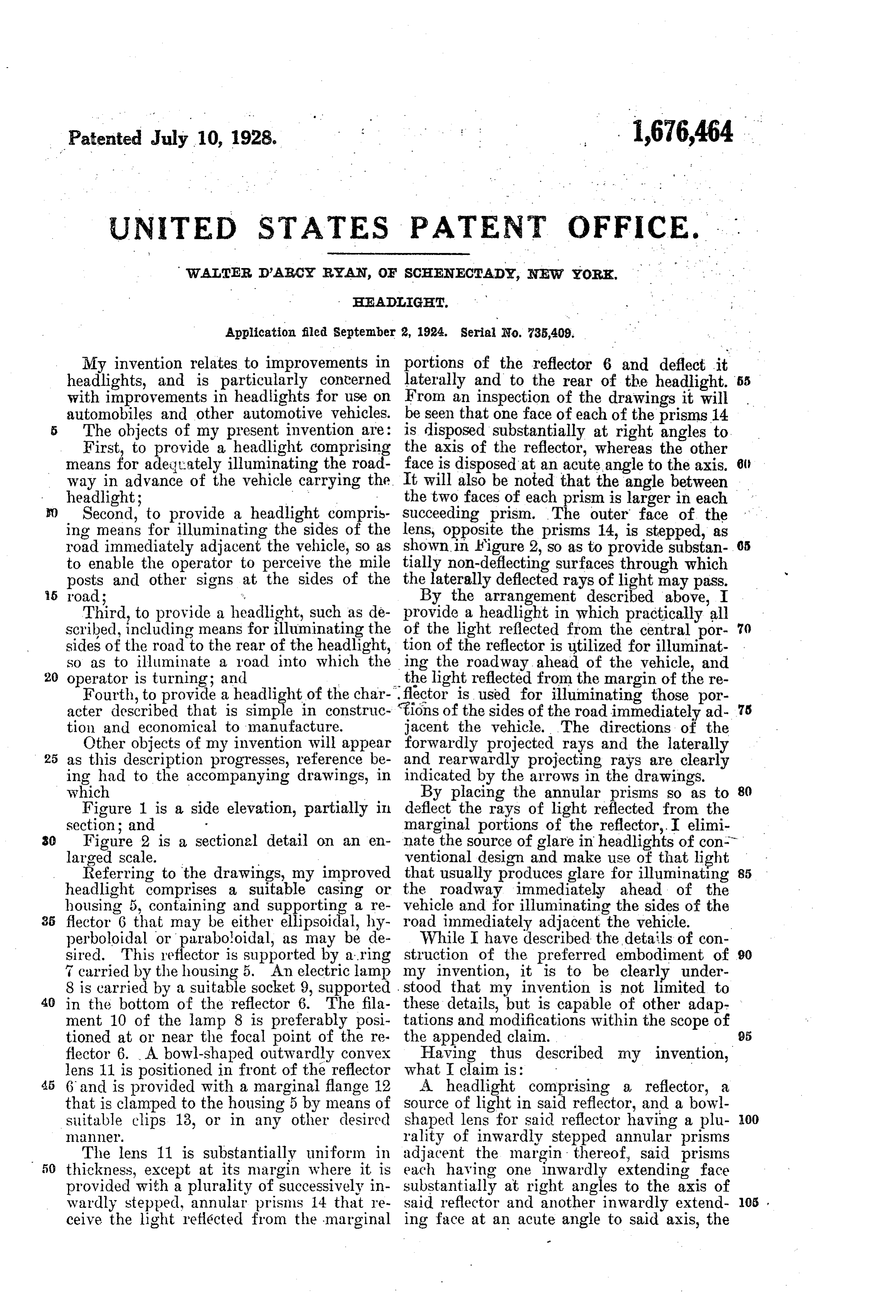
45 6 and is provided with a marginal flange 12 A headlight comprising a reflector, a that is clamped to the housing 5 by means of Source of light in said reflector, and a bowl suitable clips 13, or in any other desired shaped lens for said reflector having a plu OO le. rality of inwardly stepped annular prisms The lens 11 is substantially uniform in adjacent the margin thereof, said prisms 50 thickness, except at its margin where it is each having one inwardly extending face provided with a plurality of successively in substantially at right angles to the axis of wardly stepped, annular prisms 14 that re said reflector and another inwardly extend 05 ceive the light reflected from the marginal ing face at an acute angle to said axis, the
Page 3
angles between said faces increasing from ginal surface of said reflector will be inter the inner to the outer prism and the greater cepted by said prisms and refracted later O portion of said lens being substantially non- ally.
refractive whereby the greater portion of In witness whereof, I hereunto subscribe is the beam reflected from said reflector will be my name this 16th day of August, 1924. projected through said non-refractive por tion while the rays reflected from the mar- WALTER, D'ARCY RYAN.
Provenance
- Collection
- Cited prior art
- Original PDF
- patentimages.storage.googleapis.com →
- Filed
- 1924-09-02
- Pages
- 3
- Method
- pdftotext (the PDF's own text layer) + pdftoppm 300dpi page scans
- Source
- Google Patents bibliographic record
- Granted
- 1928-07-10
- Inventors
- Ryan Walter D Arcy
- Transcribed from
- patentimages.storage.googleapis.com →