patent · US4108540
Refractor-reflector radiation concentrator
22 August 1978
Page 1 — bibliographic record
w is Y. seves was w
United Stat 11) 4,108,540 Anderson et al. C/ 45) Aug. 22, 1978 54 REFRACTOR-REFLECTOR RADIATION FOREIGN PATENT DOCUMENTS
CONCENTRATOR
75) Inventors: Raymond H. Anderson, St. Mary's 666.222 2/1952 United Kingdom. Point; Dennis F. Wanderwerf, Cottage Primary Examiner-Conrad J. Clark
Grove, both of Minn. Attorney, Agent, or Firm-Cruzan Alexander; Donald 73 Assignee: Minnesota Mining and M. Sell; John C. Barnes
Manufacturing Company, St. Paul, 57 ABSTRACT
Minn.
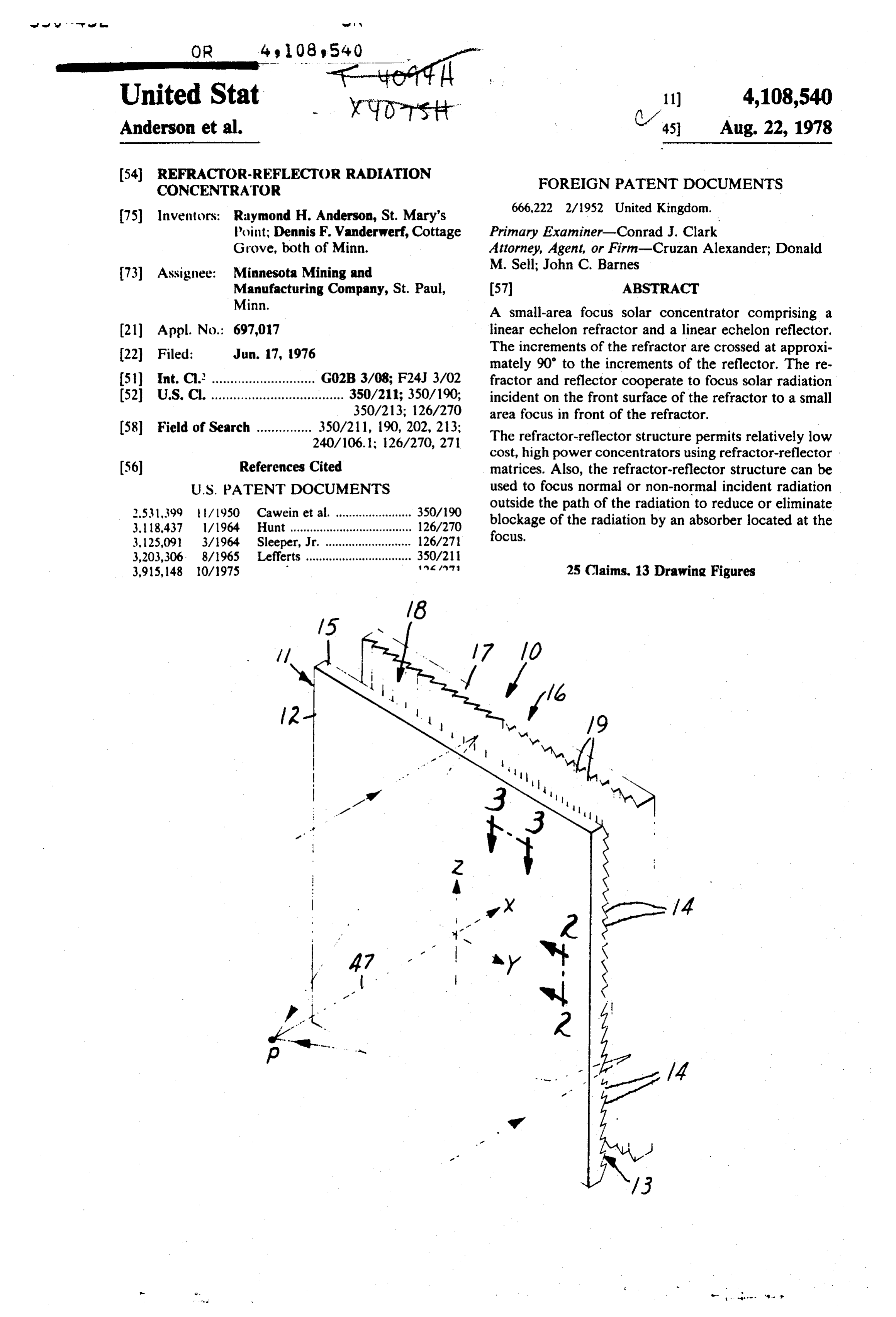
A small-area focus solar concentrator comprising a (21) Appl. No.: 697,017 linear echelon refractor and a linear echelon reflector. 22 Filed: Jun. 17, 1976 The increments of the refractor are crossed at approxi mately 90' to the increments of the reflector. The re 5 Int. Cl. ............................ G02B 3/08; F24J 3/02 fractor and reflector cooperate to focus solar radiation 52 U.S. C. .................................... 350/211; 350/190; incident on the front surface of the refractor to a small 350/213; 126/270 area focus in front of the refractor.
(58) Field of Search ............... 350/211, 190, 202, 23; The refractor-reflector structure permits relatively low
cost, high power concentrators using refractor-reflector (56) References Cited matrices. Also, the refractor-reflector structure can be
2.531,399 ft/1950 Cawein et al. ....................... 350/90 outside the path of the radiation to reduce or eliminate 3,118,437 l/1964 Hunt ..................................... 126/270 blockage of the radiation by an absorber located at the 3,125,091 3/1964 Sleeper, Jr. .......................... 126/271 focus.
3,203,306 - 8/1965 Lefferts ................................ 350/21 3,915,148 10/1975 Mav? a 25 Claims. 13 Drawing Figures
Page 2
Drawing sheet — no readable text.
Page 3
Drawing sheet — no readable text.
Page 4
Drawing sheet — no readable text.
Page 5
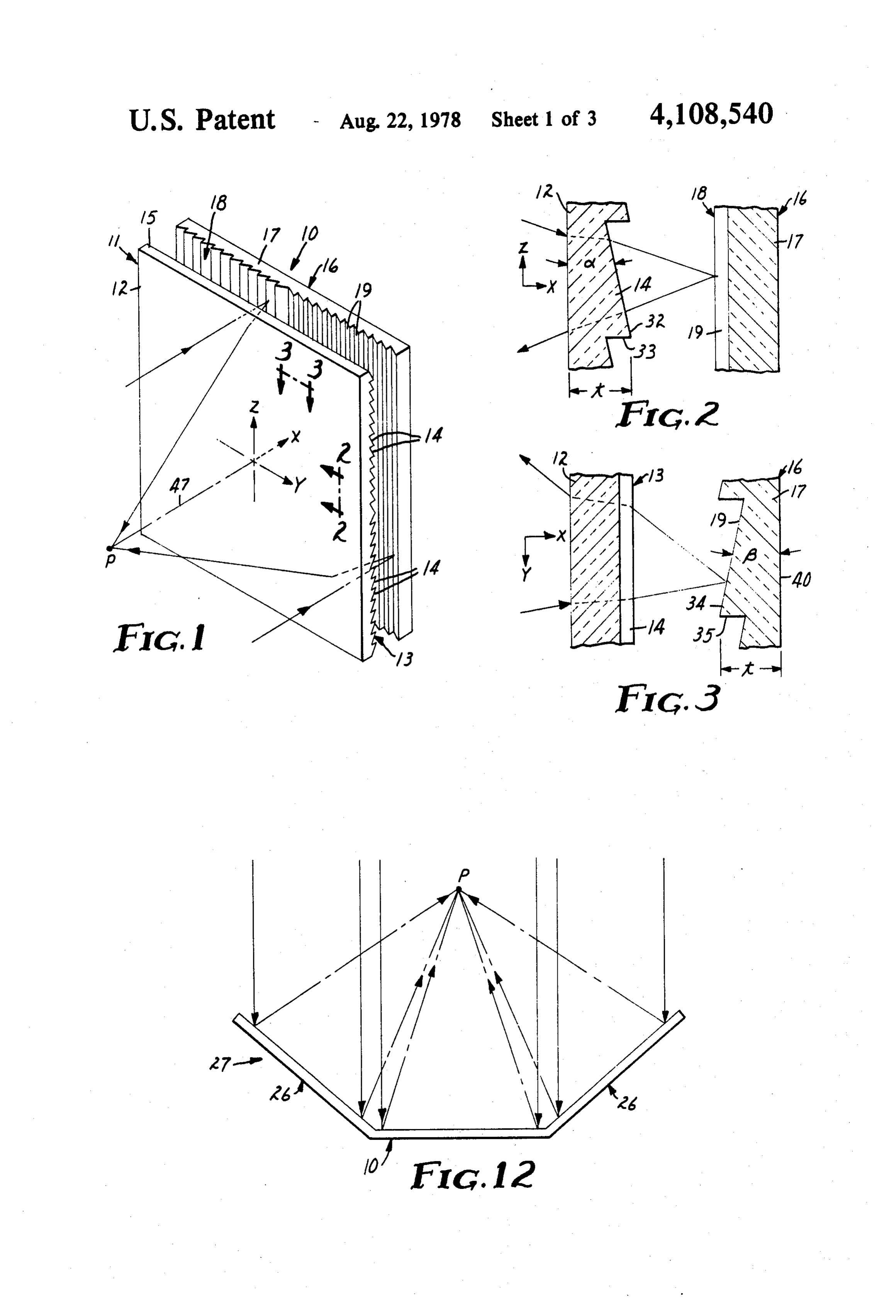
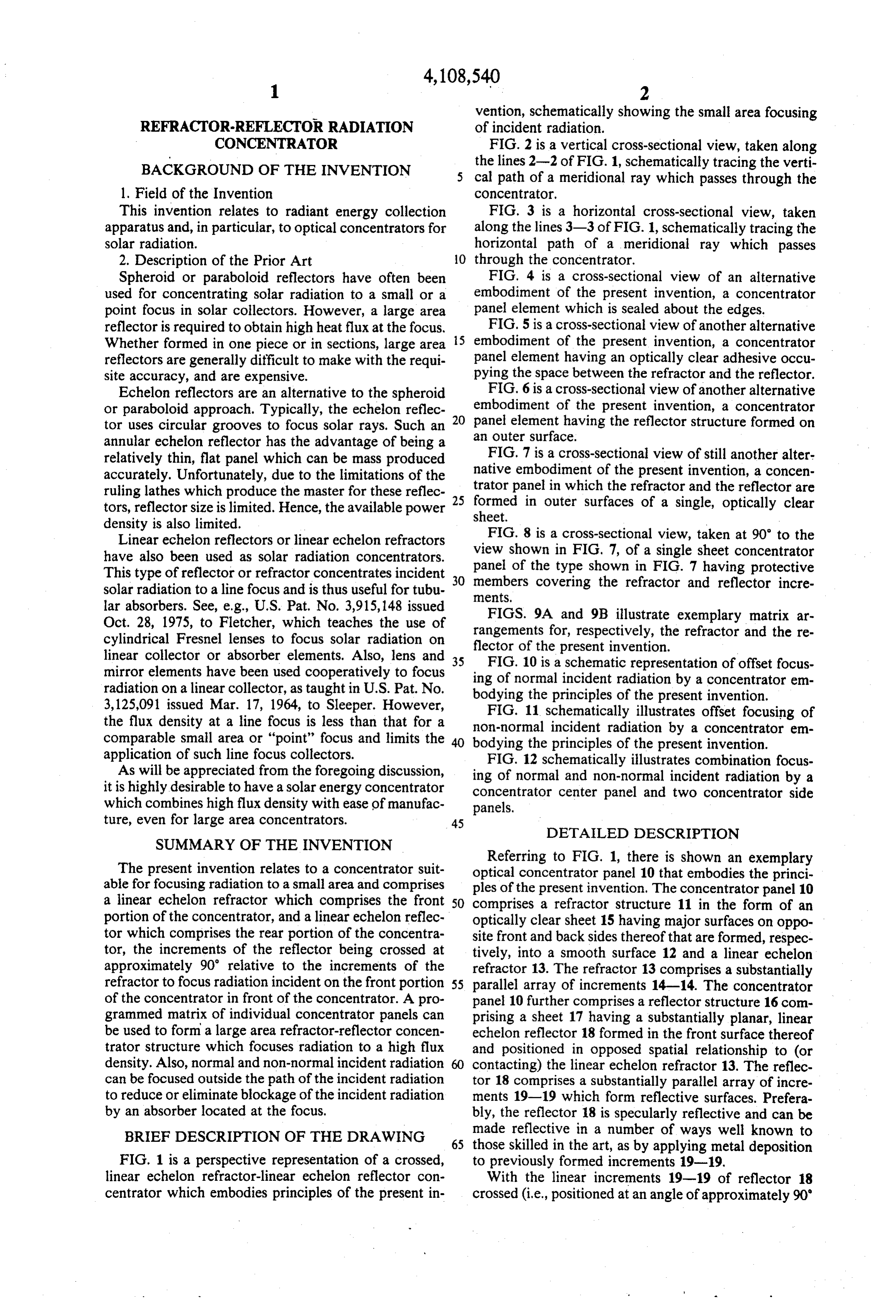
vention, schematically showing the small area focusing
REFRACTOR-REFLECTOR RADIATION of incident radiation.
CONCENTRATOR FIG. 2 is a vertical cross-sectional view, taken along BACKGROUND OF THE INVENTION the lines 2-2 of FIG. 1, schematically tracing the verti cal path of a meridional ray which passes through the 1. Field of the Invention COnCentrator,
This invention relates to radiant energy collection FIG. 3 is a horizontal cross-sectional view, taken apparatus and, in particular, to optical concentrators for along the lines 3-3 of FIG. 1, schematically tracing the solar radiation. horizontal path of a meridional ray which passes 2. Description of the Prior Art O through the concentrator.
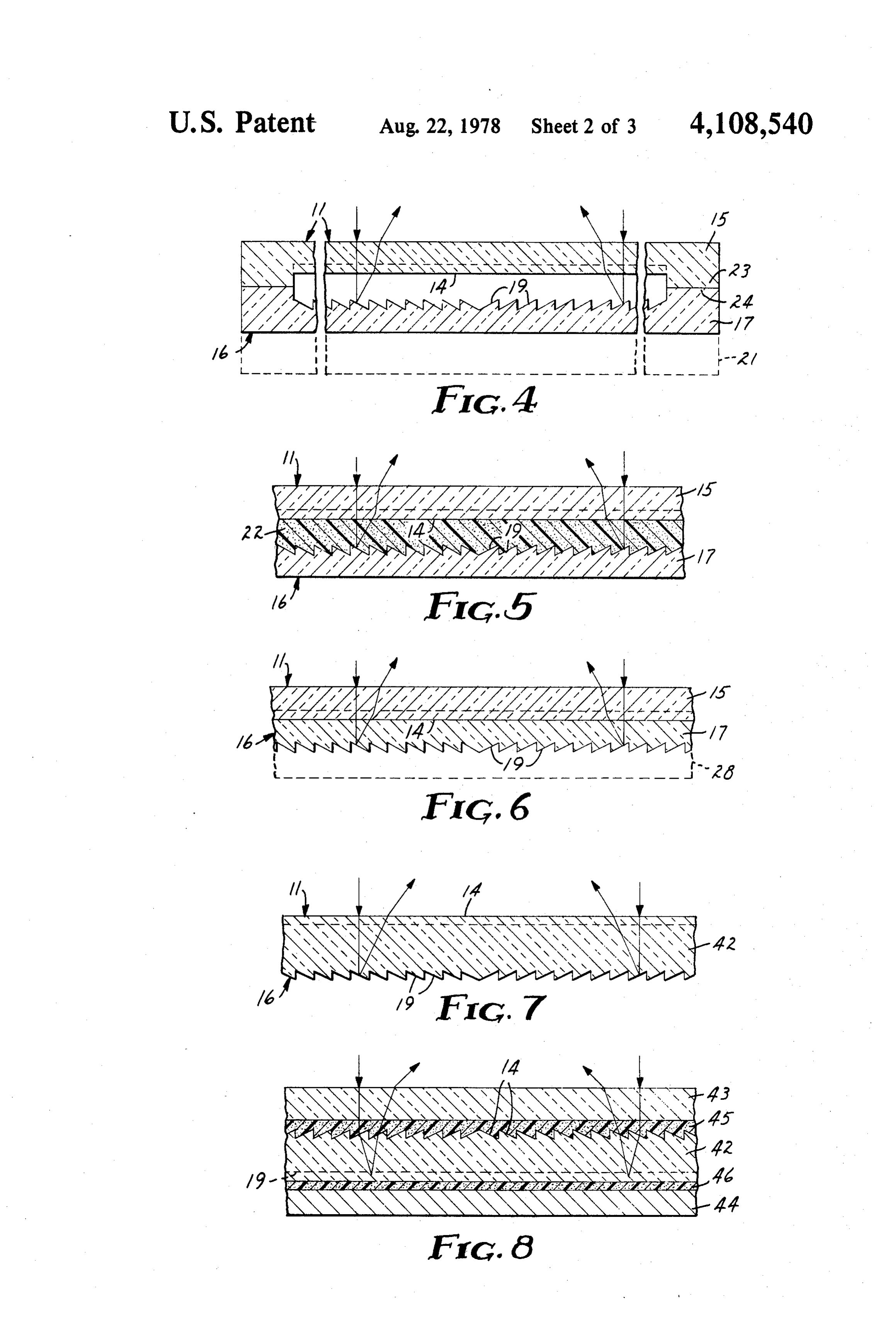
Spheroid or paraboloid reflectors have often been FIG. 4 is a cross-sectional view of an alternative used for concentrating solar radiation to a small or a embodiment of the present invention, a concentrator point focus in solar collectors. However, a large area panel element which is sealed about the edges. reflector is required to obtain high heat flux at the focus. FIG. 5 is a cross-sectional view of another alternative Whether formed in one piece or in sections, large area 15 embodiment of the present invention, a concentrator reflectors are generally difficult to make with the requi panel element having an optically clear adhesive occu site accuracy, and are expensive. pying the space between the refractor and the reflector. Echelon reflectors are an alternative to the spheroid FIG. 6 is a cross-sectional view of another alternative or paraboloid approach. Typically, the echelon reflec 20 embodiment of the present invention, a concentrator tor uses circular grooves to focus solar rays. Such an panel element having the reflector structure formed on annular echelon reflector has the advantage of being a an outer surface.
relatively thin, flat panel which can be mass produced FIG. 7 is a cross-sectional view of still another alter accurately. Unfortunately, due to the limitations of the native embodiment of the present invention, a concen ruling lathes which produce the master for these reflec trator panel in which the refractor and the reflector are tors, reflector size is limited. Hence, the available power 25 formed in outer surfaces of a single, optically clear sheet.
density is also limited.
Linear echelon reflectors or linear echelon refractors FIG. 8 is a cross-sectional view, taken at 90° to the have also been used as solar radiation concentrators. view shown in FIG. 7, of a single sheet concentrator panel
This type of reflector or refractor concentrates incident 30 membersof the type shown in FIG. 7 having protective solar radiation to a line focus and is thus useful for tubu covering the refractor and reflector incre ments.
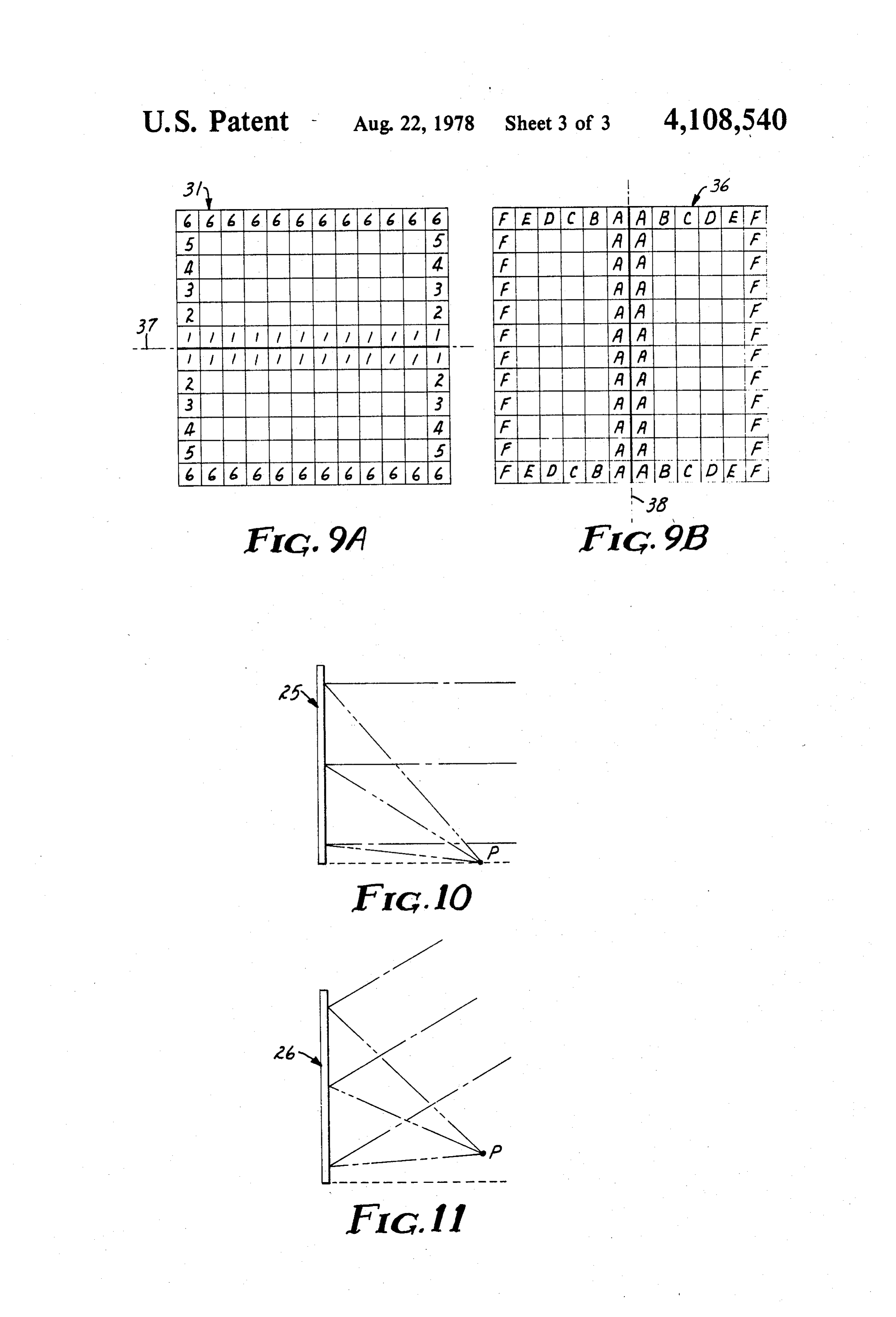
lar absorbers. See, e.g., U.S. Pat. No. 3,915,148 issued FIGS. 9A and 9B illustrate exemplary matrix ar Oct. 28, 1975, to Fletcher, which teaches the use of rangements cylindrical Fresnel lenses to focus solar radiation on flector of thefor,present respectively, the refractor and the re invention.
linear collector or absorber elements. Also, lens and 35 FIG. 10 is a schematic representation of offset focus mirror elements have been used cooperatively to focus ing of normal incident radiation by a concentrator em radiation on a linear collector, as taught in U.S. Pat. No. bodying the principles of the present invention. 3,125,091 issued Mar. 17, 1964, to Sleeper. However, FIG. 11 schematically illustrates offset focusing of the flux density at a line focus is less than that for a non-normal incident radiation by a concentrator comparable small area or "point" focus and limits the bodying the principles of the present invention. em application of such line focus collectors. FIG. 12 schematically illustrates combination focus As will be appreciated from the foregoing discussion, ing of normal and non-normal incident radiation by a it is highly desirable to have a solar energy concentrator which combines high flux density with ease of manufac concentrator panels.
center panel and two concentrator side ture, even for large area concentrators. 45
DETAILED DESCRIPTION
SUMMARY OF THE INVENTION
Referring to FIG. 1, there is shown an exemplary
The present invention relates to a concentrator suit optical concentrator panel 10 that embodies the princi able for focusing radiation to a small area and comprises ples of the present invention. The concentrator panel 10 a linear echelon refractor which comprises the front 50 comprises a refractor structure 11 in the form of an portion of the concentrator, and a linear echelon reflec optically clear sheet 15 having major surfaces on oppo tor which comprises the rear portion of the concentra site front and back sides thereof that are formed, respec tor, the increments of the reflector being crossed at tively, into a smooth surface 12 and a linear echelon approximately 90' relative to the increments of the refractor 13. The refractor 13 comprises a substantially refractor to focus radiation incident on the front portion 55 parallel array of increments 14-14. The concentrator of the concentrator in front of the concentrator. A pro panel 10 further comprises a reflector structure 16 com grammed matrix of individual concentrator panels can prising a sheet 17 having a substantially planar, linear be used to form a large area refractor-reflector concen echelon reflector 18 formed in the front surface thereof trator structure which focuses radiation to a high flux and positioned in opposed spatial relationship to (or density. Also, normal and non-normal incident radiation contacting) the linear echelon refractor 13. The reflec can be focused outside the path of the incident radiation tor 18 comprises a substantially parallel array of incre to reduce or eliminate blockage of the incident radiation ments 19-19 which form reflective surfaces. Prefera by an absorber located at the focus. bly, the reflector 18 is specularly reflective and can be BRIEF DESCRIPTION OF THE DRAWING 65 made reflective in a number of ways well known to those skilled in the art, as by applying metal deposition
FIG. 1 is a perspective representation of a crossed, to previously formed increments 19-19. linear echelon refractor-linear echelon reflector con With the linear increments 19-19 of reflector 18 centrator which embodies principles of the present in crossed (i.e., positioned at an angle of approximately 90'
Page 6
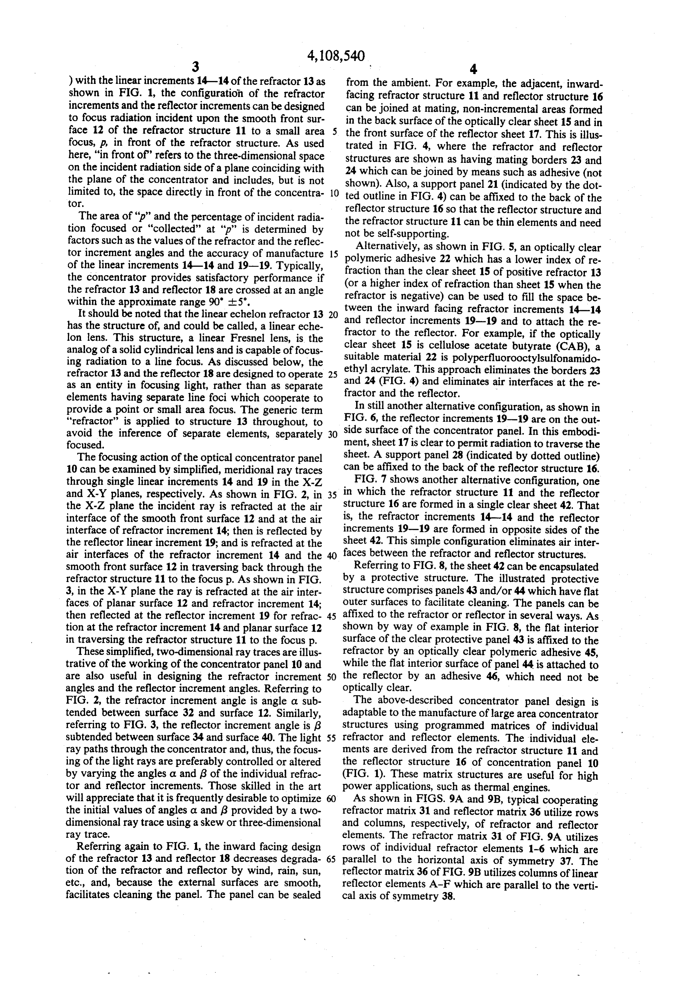
) with the linear increments 14-14 of the refractor 13 as from the ambient. For example, the adjacent, inward shown in FIG. 1, the configuration of the refractor facing refractor structure 11 and reflector structure 16 increments and the reflector increments can be designed can be joined at mating, non-incremental areas formed to focus radiation incident upon the smooth front sur in the back surface of the optically clear sheet 15 and in face 12 of the refractor structure 11 to a small area the front surface of the reflector sheet 17. This is illus focus, p, in front of the refractor structure. As used trated in FIG. 4, where the refractor and reflector here, "in front of" refers to the three-dimensional space structures are shown as having mating borders 23 and on the incident radiation side of a plane coinciding with 24 which can be joined by means such as adhesive (not the plane of the concentrator and includes, but is not shown). Also, a support panel 21 (indicated by the dot limited to, the space directly in front of the concentra 10 ted outline in FIG. 4) can be affixed to the back of the tor.
reflector structure 16 so that the reflector structure and
The area of "p" and the percentage of incident radia the refractor structure 11 can be thin elements and need tion focused or "collected' at "p" is determined by not be self-supporting.
factors such as the values of the refractor and the reflec
Alternatively, as shown in FIG. 5, an optically clear tor increment angles and the accuracy of manufacture 15 polymeric of the linear increments 14-14 and 19-19. Typically, fraction than adhesive 22 which has a lower index of re the concentrator provides satisfactory performance if (or a higher index the clear sheet 15 of positive refractor 13 the refractor 13 and reflector 18 are crossed at an angle refractor is negative) of refraction than sheet 15 when the within the approximate range 90' -ts'. can be used to fill the space be It should be noted that the linear echelon refractor 13 20 tween the inward facing refractor increments 14-14 has the structure of, and could be called, a linear eche and reflector increments 19-19 and to attach the re lon lens. This structure, a linear Fresnel lens, is the fractor to the reflector. For example, if the optically analog of a solid cylindrical lens and is capable of focus clear sheet 15 is cellulose acetate butyrate (CAB), a suitable material 22 is polyperfluorooctylsulfonamido ing radiation to a line focus. As discussed below, the ethyl acrylate. This approach eliminates the borders 23 refractor 13 and the reflector 18 are designed to operate 25 as an entity in focusing light, rather than as separate and 24 (FIG. 4) and eliminates air interfaces at the re elements having separate line foci which cooperate to fractor and the reflector.
provide a point or small area focus. The generic term In still another alternative configuration, as shown in “refractor” is applied to structure 13 throughout, to FIG. 6, the reflector increments 19-19 are on the out avoid the inference of separate elements, separately 30 side surface of the concentrator panel. In this embodi focused. ment, sheet 17 is clear to permit radiation to traverse the The focusing action of the optical concentrator panel sheet. A support panel 28 (indicated by dotted outline) 10 can be examined by simplified, meridional ray traces can be affixed to the back of the reflector structure 16. through single linear increments 14 and 19 in the X-Z FIG. 7 shows another alternative configuration, one and X-Y planes, respectively. As shown in FIG. 2, in 35 in which the refractor structure 11 and the reflector the X-Z plane the incident ray is refracted at the air structure 16 are formed in a single clear sheet 42. That interface of the smooth front surface 12 and at the air is, the refractor increments 14-14 and the reflector interface of refractor increment 14; then is reflected by increments 19-19 are formed in opposite sides of the the reflector linear increment 19; and is refracted at the sheet 42. This simple configuration eliminates air inter air interfaces of the refractor increment 14 and the faces between the refractor and reflector structures. smooth front surface 12 in traversing back through the Referring to FIG. 8, the sheet 42 can be encapsulated refractor structure 11 to the focus p. As shown in FIG. by a protective structure. The illustrated protective 3, in the X-Y plane the ray is refracted at the air inter Structure comprises panels 43 and/or 44 which have flat faces of planar surface 12 and refractor increment 14; outer surfaces to facilitate cleaning. The panels can be then reflected at the reflector increment 19 for refrac 45 affixed to the refractor or reflector in several ways. As tion at the refractor increment 14 and planar surface 12 shown by way of example in FIG. 8, the flat interior in traversing the refractor structure 11 to the focus p. surface of the clear protective panel 43 is affixed to the These simplified, two-dimensional ray traces are illus refractor by an optically clear polymeric adhesive 45, trative of the working of the concentrator panel 10 and while the flat interior surface of panel 44 is attached to are also useful in designing the refractor increment 50 the reflector by an adhesive 46, which need not be angles and the reflector increment angles. Referring to optically clear.
FIG. 2, the refractor increment angle is angle a sub The above-described concentrator panel design is tended between surface 32 and surface 12. Similarly, adaptable to the manufacture of large area concentrator referring to FIG. 3, the reflector increment angle is g structures using programmed matrices of individual subtended between surface 34 and surface 40. The light 55 refractor and reflector elements. The individual ele ray paths through the concentrator and, thus, the focus ments are derived from the refractor structure 11 and ing of the light rays are preferably controlled or altered the reflector structure 16 of concentration panel 10 by varying the angles a and 3 of the individual refrac (FIG. 1). These matrix structures are useful for high tor and reflector increments. Those skilled in the art power applications, such as thermal engines. will appreciate that it is frequently desirable to optimize As shown in FIGS. 9A and 9B, typical cooperating the initial values of angles a and g provided by a two refractor matrix. 31 and reflector matrix 36 utilize rows dimensional ray trace using a skew or three-dimensional and columns, respectively, of refractor and reflector ray trace. elements. The refractor matrix. 31 of FIG. 9A utilizes Referring again to FIG. 1, the inward facing design rows of individual refractor elements 1-6 which are of the refractor 13 and reflector 18 decreases degrada 65 parallel to the horizontal axis of symmetry 37. The tion of the refractor and reflector by wind, rain, sun, reflector matrix 36 of FIG.9B utilizes columns of linear etc., and, because the external surfaces are smooth, reflector elements A-F which are parallel to the verti facilitates cleaning the panel. The panel can be sealed cal axis of symmetry 38.
Page 7
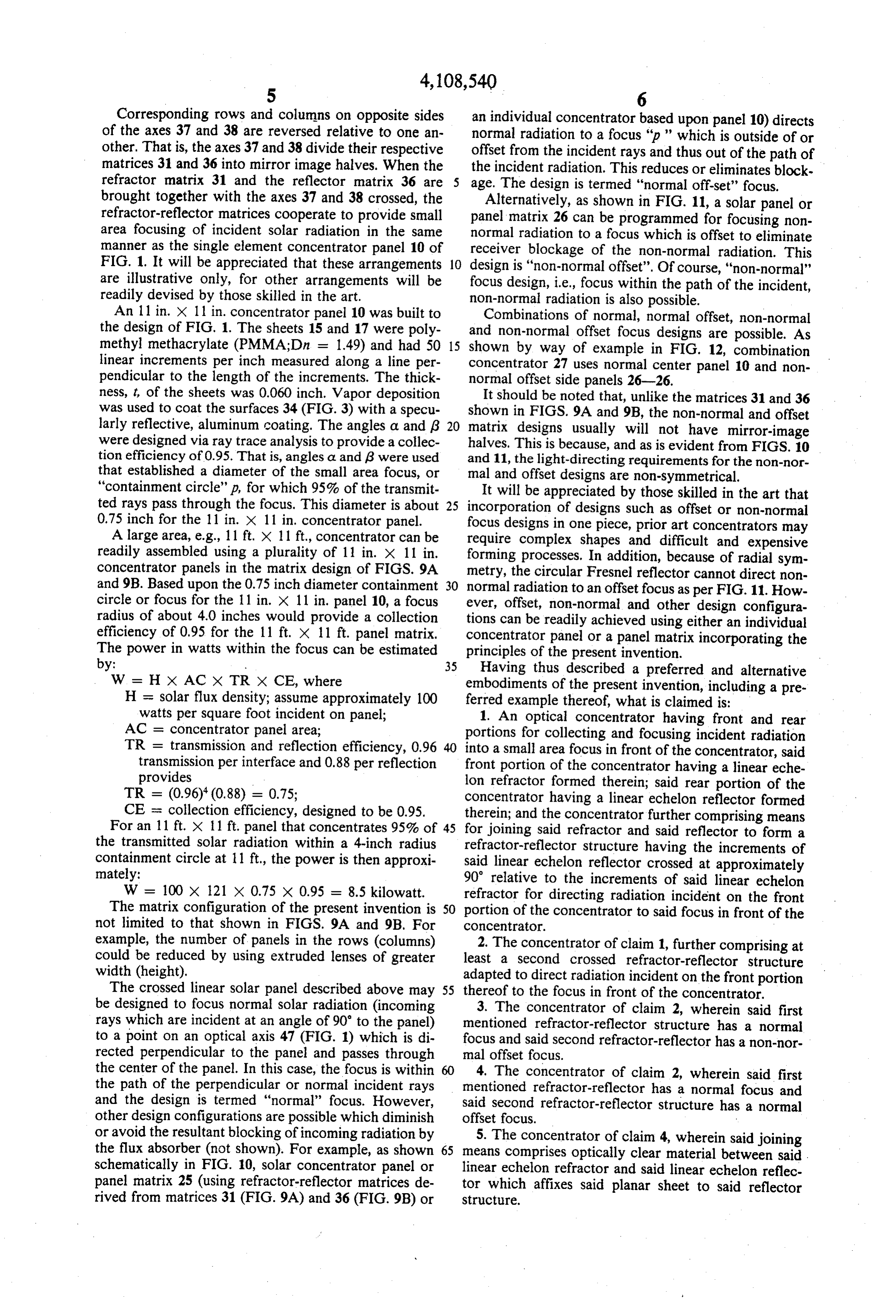
Corresponding rows and columns on opposite sides an individual concentrator based upon panel 10) directs of the axes 37 and 38 are reversed relative to one an normal radiation to a focus "p ' which is outside of or other. That is, the axes 37 and 38 divide their respective offset from the incident rays and thus out of the path of matrices 31 and 36 into mirror image halves. When the the incident radiation. This reduces or eliminates block refractor matrix. 31 and the reflector matrix 36 are 5 age. The design is termed "normal off-set' focus. brought together with the axes 37 and 38 crossed, the Alternatively, as shown in FIG. 11, a solar panel or refractor-reflector matrices cooperate to provide small panel matrix 26 can be programmed for focusing non area focusing of incident solar radiation in the same normal radiation to a focus which is offset to eliminate manner as the single element concentrator panel 10 of receiver blockage of the non-normal radiation. This FIG. 1. It will be appreciated that these arrangements 10 design is "non-normal offset'. Of course, "non-normal" are illustrative only, for other arrangements will be focus design, i.e., focus within the path of the incident, readily devised by those skilled in the art. non-normal radiation is also possible. An 11 in. x 11 in. concentrator panel 10 was built to Combinations of normal, normal offset, non-normal the design of FIG. 1. The sheets 15 and 17 were poly and non-normal offset focus designs are possible. As methyl methacrylate (PMMA;Dn = 1.49) and had 50 15 shown by way of example in FIG. 12, combination linear increments per inch measured along a line per concentrator 27 uses normal center panel 10 and non pendicular to the length of the increments. The thick normal offset side panels 26-26.
ness, t, of the sheets was 0.060 inch. Vapor deposition It should be noted that, unlike the matrices 31 and 36 was used to coat the surfaces 34 (FIG. 3) with a specu shown in FIGS. 9A and 9B, the non-normal and offset larly reflective, aluminum coating. The angles a and (3 20 matrix designs usually will not have mirror-image were designed via ray trace analysis to provide a collec halves. This is because, and as is evident from FIGS. 10 tion efficiency of 0.95. That is, angles a and g were used and 11, the light-directing requirements for the non-nor that established a diameter of the small area focus, or mal and offset designs are non-symmetrical. "containment circle"p, for which 95% of the transmit It will be appreciated by those skilled in the art that ted rays pass through the focus. This diameter is about 25 incorporation of designs such as offset or non-normal 0.75 inch for the 11 in. x 11 in. concentrator panel. focus designs in one piece, prior art concentrators may A large area, e.g., 11 ft. X 11 ft., concentrator can be require complex shapes and difficult and expensive readily assembled using a plurality of 11 in. X 11 in. forming processes. In addition, because of radial sym concentrator panels in the matrix design of FIGS. 9A metry, the circular Fresnel reflector cannot direct non and 9B. Based upon the 0.75 inch diameter containment 30 normal radiation to an offset focus as per FIG. 11. How circle or focus for the 11 in. X 11 in. panel 10, a focus ever, offset, non-normal and other design configura radius of about 4.0 inches would provide a collection tions can be readily achieved using either an individual efficiency of 0.95 for the 11 ft. x 11 ft. panel matrix. concentrator panel or a panel matrix incorporating the The power in watts within the focus can be estimated principles of the present invention. by: 35 Having thus described a preferred and alternative W = H X AC X TR X CE, where embodiments of the present invention, including a pre H = solar flux density; assume approximately 100 ferred example thereof, what is claimed is: watts per square foot incident on panel; 1. An optical concentrator having front and rear AC = concentrator panel area; portions for collecting and focusing incident radiation TR = transmission and reflection efficiency, 0.96 40 into a small area focus in front of the concentrator, said transmission per interface and 0.88 per reflection front portion of the concentrator having a linear eche provides lon refractor formed therein; said rear portion of the TR = (0.96) (0.88) = 0.75; concentrator having a linear echelon reflector formed CE = collection efficiency, designed to be 0.95. therein; and the concentrator further comprising means For an 11 ft. x 11 ft. panel that concentrates 95% of 45 for joining said refractor and said reflector to form a the transmitted solar radiation within a 4-inch radius refractor-reflector structure having the increments of containment circle at 11 ft, the power is then approxi said linear echelon reflector crossed at approximately mately: 90 relative to the increments of said linear echelon W - 100 x 121 x 0.75 x 0.95 = 8.5 kilowatt. refractor for directing radiation incident on the front The matrix configuration of the present invention is 50 portion of the concentrator to said focus in front of the not limited to that shown in FIGS. 9A and 9B, For COncentrator.
example, the number of panels in the rows (columns) 2. The concentrator of claim 1, further comprising at could be reduced by using extruded lenses of greater least a second crossed refractor-reflector structure width (height). adapted to direct radiation incident on the front portion The crossed linear solar panel described above may 55 thereof to the focus in front of the concentrator. be designed to focus normal solar radiation (incoming 3. The concentrator of claim 2, wherein said first rays which are incident at an angle of 90 to the panel) mentioned refractor-reflector structure has a normal to a point on an optical axis 47 (FIG. 1) which is di focus and said second refractor-reflector has a non-nor rected perpendicular to the panel and passes through mal offset focus.
the center of the panel. In this case, the focus is within 60 4. The concentrator of claim 2, wherein said first the path of the perpendicular or normal incident rays mentioned refractor-reflector has a normal focus and and the design is termed "normal" focus. However, said second refractor-reflector structure has a normal other design configurations are possible which diminish offset focus.
or avoid the resultant blocking of incoming radiation by 5. The concentrator of claim 4, wherein said joining the flux absorber (not shown). For example, as shown 65 means comprises optically clear material between said . schematically in FIG. 10, solar concentrator panel or linear echelon refractor and said linear echelon reflec panel matrix 25 (using refractor-reflector matrices de tor which affixes said planar sheet to said reflector rived from matrices 31 (FIG. 9A) and 36 (FIG. 9B) or Structure.
Page 8
6. The concentrator of claim 2, said front portion comprising a reflector structure having at least a first comprising a planar sheet of optically clear material substantially planar major surface and a linear echelon having first and second major surfaces on opposite sides reflector formed in said first major surface of the reflec thereof, said first major surface being substantially to structure.
smooth and said second major surface having a linear 16. The concentrator of claim 15, wherein said join echelon refractor formed therein; and said rear portion ing means comprises mating, non-incremental portions comprising a reflector structure having at least a first formed in said second major surface of the planar sheet substantially planar major surface and a linear echelon and in said first major surface of the reflector structure. reflector formed in said first major surface of the reflec 17. The concentrator of claim 16, wherein said major to structure. O surfaces are approximately 11 in. by l l in. and wherein 7. The concentrator of claim 6, wherein said major said refractor increments and said reflector increments surfaces are approximately 11 in. by 11 in. and wherein number approximately fifty per inch measured along a said refractor increments and said reflector increments line extending perpendicular to the length of the incre number approximately 50 per inch measured along a ments, and said planar sheet being approximately 0.060 line extending perpendicular to the length of the incre 15 inches thick for providing a collection efficiency of 0.95 ments, and said planar sheet being approximately 0.060 within a focus of approximately 0.75 inch diameter. inches thick for providing a collection efficiency of 0.95 18. The concentrator of claim 15, wherein said join within a focus of approximately 0.75 inch diameter. ing means comprises optically clear material between 8. The concentrator of claim 6, wherein said joining said linear echelon refractor and said linear echelon means comprises mating, non-incremental portions 20 reflector which affixes said planar sheet to said reflector formed in said second major surface of the planar sheet Structure.
and in said first major surface of the reflector structure. 19. The concentrator of claim 18, wherein said major 9. The concentrator of claim 8, wherein said major surfaces are approximately 11 in. by 11 in. and wherein surfaces are approximately 11 in. by 11 in. and wherein said refractor increments and said reflector increments said refractor increments and said reflector increments 25 number approximately 50 per inch measured along a number approximately 50 per inch measured along a line extending perpendicular to the length of the incre line extending perpendicular to the length of the incre ments, and said planar sheet being approximately 0.060 ments, and said planar sheet being approximately 0.060 inches thick for providing a collection efficiency of 0.95 inches thick for providing a collection efficiency of 0.95 within a focus of approximately 0.75 inch diameter. within a focus of approximately 0.75 inch diameter. 30 20. The concentrator of claim 15, wherein said reflec 10. The concentrator of claim 8, wherein said major tor structure is an optically clear sheet having a second surfaces are approximately 11 in. by 11 in. and wherein substantially planar major surface on the opposite side said refractor increments and said reflector increments of said structure from said first major surface, said sec number approximately 50 per inch measured along a ond major surface of the reflector structure being closer line extending perpendicular to the length of the incre 35 to said planar sheet than said first major surface of the ments, and said planar sheet being approximately 0.060 reflector structure.
inches thick for providing a collection efficiency of 0.95 21. The concentrator of claim 20, wherein said major within a focus of approximately 0.75 inch diameter. surfaces are approximately 11 in. by 11 in. and wherein 11. The concentrator of claim 6, wherein said reflec said refractor increments and said reflector increments tor structure is an optically clear sheet having a second number approximately 50 per inch measured along a substantially planar major surface on the opposite side line extending perpendicular to the length of the incre of said structure from said first major surface, said sec ments, and said planar sheet being approximately 0.060 ond major surface of the reflector structure being closer inches thick for providing a collection efficiency of 0.95 to said planar sheet than said first major surface of the within a focus of approximately 0.75 inch diameter. reflector structure. 45 22. The concentrator of claim 15, wherein said major 12. The concentrator of claim 11, wherein said major surfaces are approximately 11 in. by 11 in. and wherein surfaces are approximately 11 in. by 11 in, and wherein said refractor increments and said reflector increments said refractor increments and said reflector increments number approximately 50 per inch measured along a number approximately 50 per inch measured along a line extending perpendicular to the length of the incre line extending perpendicular to the length of the incre SO ments, and said planar sheet being approximately 0.060 ments, and said planar sheet being approximately 0.060 inches thick for providing a collection efficiency of 0.95 inches thick for providing a collection efficiency of 0.95 within a focus of approximately 0.75 inch diameter. within a focus of approximately 0.75 inch diameter. 23. The concentrator of claim 1, said joining means 13. The concentrator of claim 2, wherein said joining comprising an optically clear sheet having front and means comprising an optically clear sheet having front 55 rear major surfaces, said linear echelon refractor and and rear major surfaces, said linear echelon refractor said linear echelon reflector being formed, respectively, and said linear echelon reflector being formed, respec in said front major surface and said rear major surface. tively, in said front major surface and said rear major 24. The concentrator of claim 23, at least one of said surface. linear echelon refractor and said linear echelon reflec 14. The concentrator of claim 13, wherein at least one tor having a protective covering thereover. of said linear echelon refractor and said linear echelon 25. A concentrator for focusing radiation to a small reflector having a protective covering thereover. area of high flux intensity and comprising at least two 15. The concentrator of claim 1, said front portion concentrator panels, each panel comprising: comprising a planar sheet of optically clear material a planar sheet of optically clear material having first having first and second major surfaces on opposite sides 65 and second major surfaces formed, respectively, in thereof, said first major surface being substantially front and back sides thereof, the first major surface smooth and said second major surface having a linear being substantially smooth and the second major echelon refractor formed therein; and said rear portion surface having a linear echelon lens formed therein;
Page 9
a planar, linear echelon reflector corresponding to sponding linear echelon reflector to direct radia the planar sheet of optically clear material, the increments of the linear echelon reflector being tion incident on the first, smooth major surface of crossed at approximately 90' to the increments of the planar sheet to a focus in front thereof.
the linear echelon lens cooperating with the corre- k l k is
Page 10
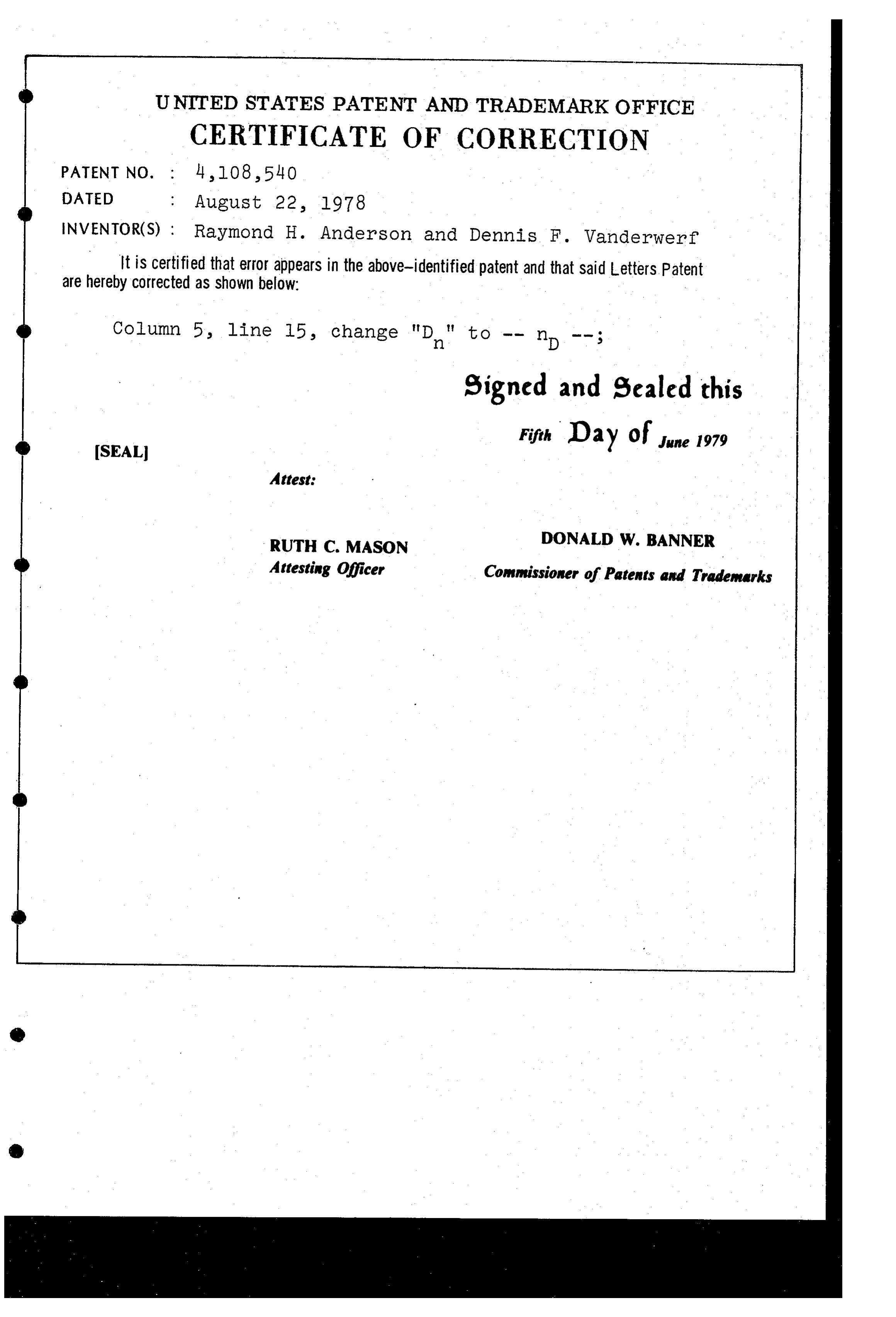
UNITED STATES PATENT AND TRADEMARK OFFICE
CERTIFICATE OF CORRECTION
INVENTOR(S) : Raymond H. Anderson and Dennis F. Wanderwerf It is certified that error appears in the above-identified patent and that said Letters Patent are hereby corrected as shown below:
Column 5 line lb., change "D." to -- np -- :
signed and sealed this
SEAL
Fifth Day of June 1979
Attest:
Attesting Officer Commissioner of Patents and Trademarks
Provenance
- Collection
- Cited prior art
- Original PDF
- patentimages.storage.googleapis.com →
- Filed
- 1976-06-17
- Pages
- 10
- Method
- pdftotext (the PDF's own text layer) + pdftoppm 300dpi page scans
- Source
- Google Patents bibliographic record
- Granted
- 1978-08-22
- Inventors
- Raymond H. Anderson; Dennis F. Vanderwerf; Minnesota Mining and Manufacturing Co
- Transcribed from
- patentimages.storage.googleapis.com →