patent · US2254961
Unitary lens system
2 September 1941
Page 1
Drawing sheet — no readable text.
Page 2
Drawing sheet — no readable text.
Page 3
Drawing sheet — no readable text.
Page 4
8Patiented Sept. 2, 94.
UNTAE ENS SSTEM
Lawrence arris, Brooklyn, N. Y., assignor to
George M. Cressaty, New York, N.Y.
Application August 21, 1937, Serial No. 160,312
This invention is directed to an improvement sion A further object of the invention is the provi in a unitary lens system involving a single casting cheaply of a lens structure which may be easily and particularly constructed so that all the light rays duced andmanufactured and automatically pro from the light source are projected in substantial and resultswhich will give identical performances with any hand ground, polished and parallel relation without spherical aberration. 5.
A primary object of the invention is the provi expensive optical lens system. sion of a lens unit which gathers substantially ingThe invention is illustrated in the accompany drawings, in which:
all the light rays from a source into a beam sub stantially uniform, whether the source is at the O the use of1a isconventional
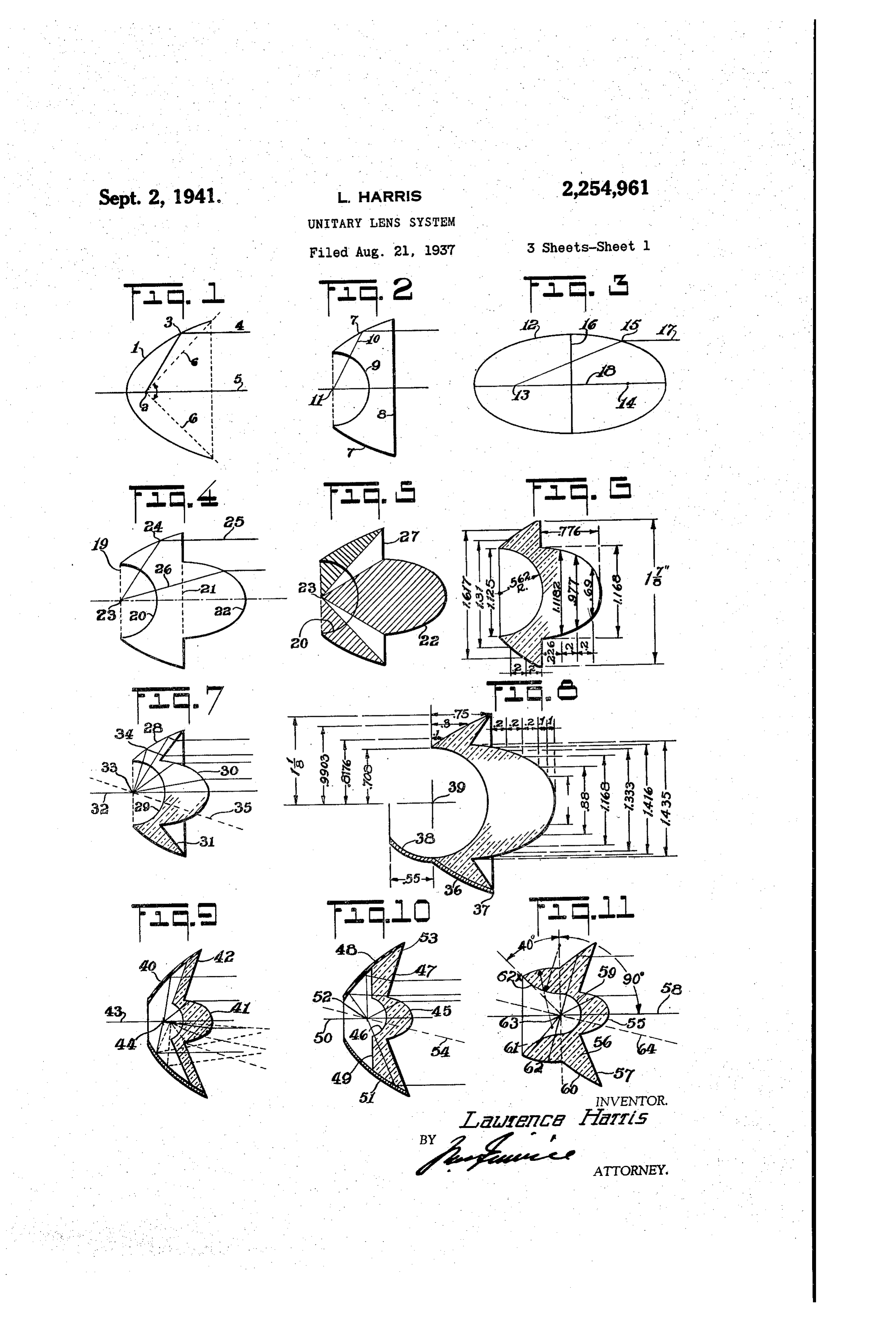
Figure a diagrammatic view illustrating parabolic reflector and focus of the unit or out of focus therewith.
A further object of the invention is the provi indicating the degree of uncontrolled light from sion of a unitary lens structure constructed to such light source.
Figure 2 is a similar view showing the lens provide one part which reflects the light rays and unit with the surface formed to function as a another part which refracts the light rays, with 5 parabolic reflector.
the parts arranged to project the rays into a uni Figure 3 is a diagrammatic view illustrating form light beam evenly distributed throughout more particularly the fundamental properties of the full area to be lighted. the elliptical refracting medium. . A further object of the invention is the provi Figure 4 is a diagrammatic view illustrating sion of a unitary lens system wherein the unit structure serves as a reflector not only for the 20 the combination of the parabolic reflector form forwardly directed rays from the light Source of Figure 2 with the elliptical lens form of Fig but also for the rearwardly directed rays from ure 3.
such source, including provision for the inversion trating Figure 5 is a sectional view of a lens unit illus of such rearwardly directed rays into substan more particularly the areas in the unit tially parallel rays to provide the desired light 25 in which the light rays pass through the unit beam and serving to concentrate the light or to without striking either the parabolic area or the diverge certain rays of the light beam to provide elliptical area.
a wider and more evenly distributed illuminated dimensions isofa view
Figure 6 similar to Figure 5 with the the various sectors marked in
A further object of the invention is the provi 30 inches.
sion of a unitary lens structure in which the unit to Figurethe is a view similar to Figure 5 modified extent that the diverted or lost rays of is constructed to provide one part which reflects the construction shown in Figure 5 are focused and another part which refracts the rays from in the same manner as the rays from the ellip the light source, the surfaces of the part Serving to refect the rays being modified to obtain vari 35 tical or parabolic Surface. Figure 8 is a view of the lens body shown in ous patterns of illumination, that is, either Syn metrically or asymmetrically depending upon the Figure with the dimensions of the various parts size and shape of the area to be lighted. marked in inches.
A further object of the invention is the provi 40 Figure 9 shows a construction similar to Fig sion of a unitary lens structure constructed with ture except that the parabolic sector is formed a view to gathering more than 270 degrees of of metal.
the light rays from the light source without the Figure 10 is a view similar to Figure modified use of separate metallic reflectors and in a rela in the relation of the parabolic surface of the tively small sized unit, thus maintaining an 45 lens and the hemispherical recess in the rear of extremely high efficiency in a lens unit of rela the lens.
tively reduced diameter. Figure 11 is a view similar to Figure a modified A further object of the invention is to form in the reflecting surface.
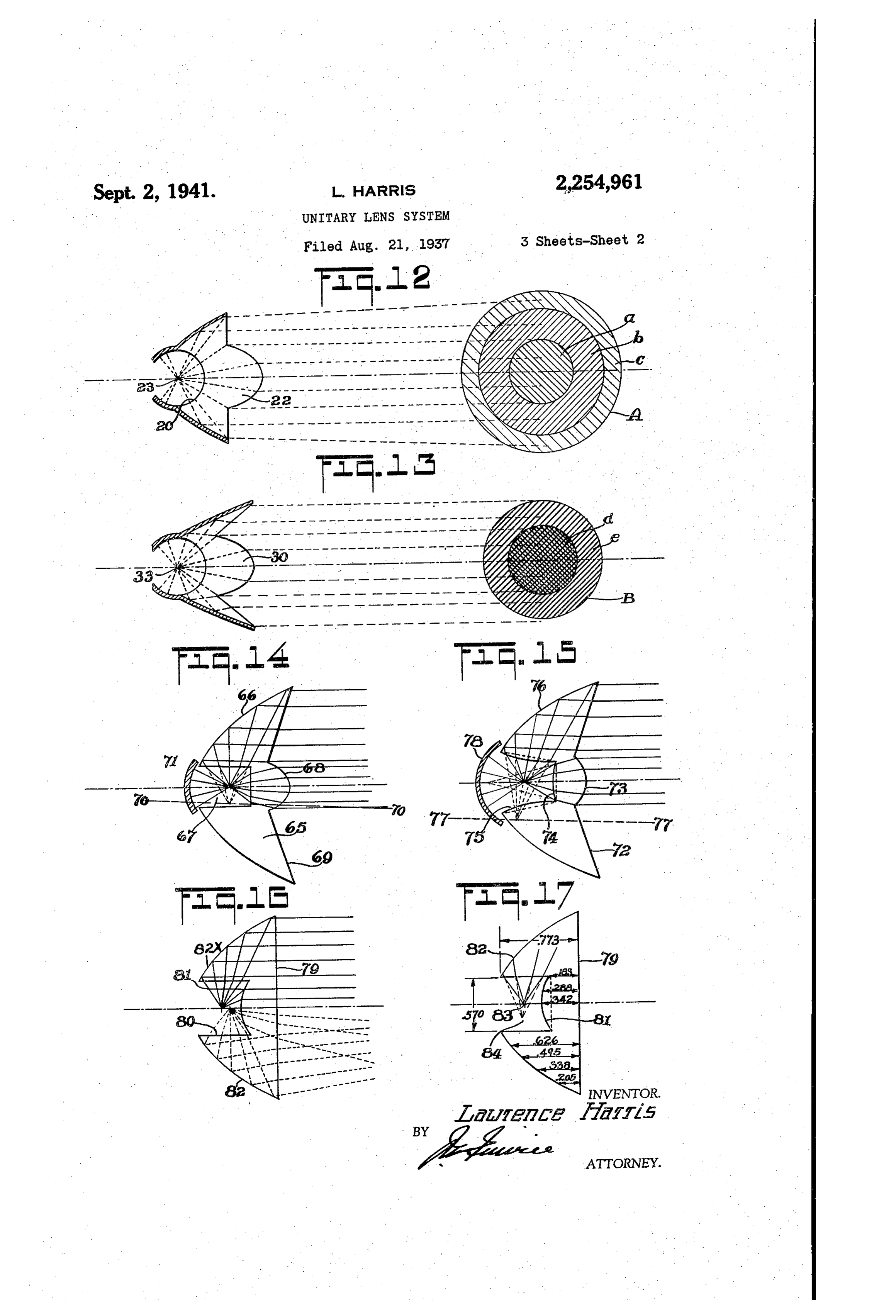
the wall or walls of the light source receiving Figure 12 illustrates diagrammatically the type well on such a curve or curves as to control the 50 of illumination produced by a lens constructed refractive influence of the body of the lens on similar to that shown in Figure 4 and provided the rays passing through said well walls to insure with a metallic reflector.
that such rays, when reflected from the reflec Figure 13 illustrates the type of illumination tive margin or directed through the central lens resulting system will result in a beam free of spherical 55 in Figurefrom.
the use of a lens of the form shown aberration.
Page 5
Figure 14 is a more or less diagrammatic view that the diameter 9 of the spherical cavity 20 of a modified form of lens.
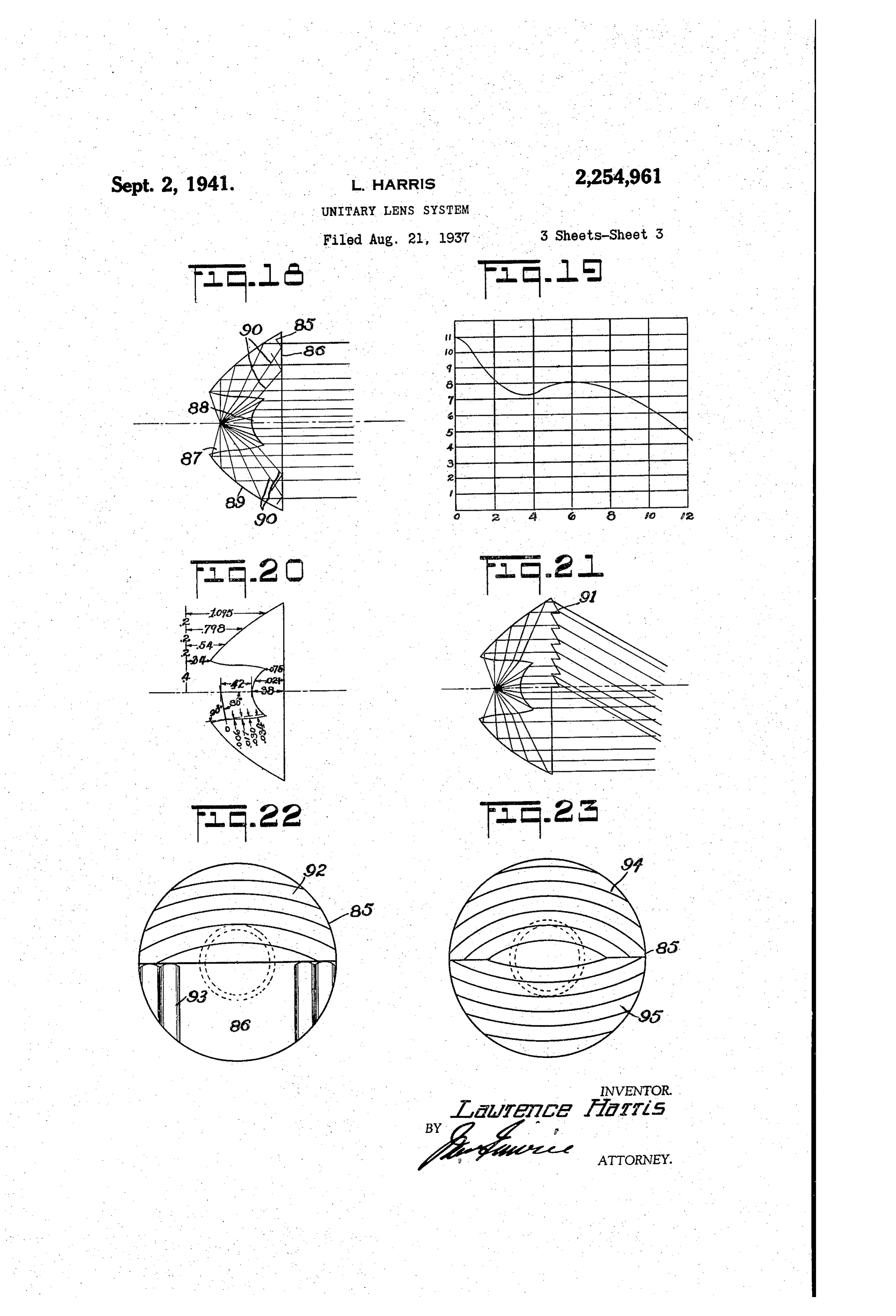
Figure 15 is a view similar to Figure 14 show in the rear of the lens is equal to the minor axis 2 of the elliptical section 22 and the focus of ing a modified construction with respect thereto. the parabolic section coincides with the focus of Figure 16 illustrates a further modification of 5 the elliptical section, as at 23. . the type of lens body shown in Figure 14. Under these conditions, a ray from 23 imping Figure 17 is a similar view showing the dinen ing on the parabolic section at 24 will be reflected sions marked in inches. from 24 in the direction 25 while a ray 26 im Figure 18 shows a modified form of the lens pinging of Figure 16 with particular regard to the form O fracted on the elliptical section 22 will be re in passing from the elliptical section of the annular wall of the well surface to control though undergoing no refraction on entering the refraction of the entering rayS.
Figure 19 is a diagram illustrating the distribu lens through the Semi-circular surface 20. The lens shown in Figures 4 and 5 has para tion of illumination from the improved lens. bolic margins with a spherical depression cr cav Figure 20 shows diagrammatically the detailed 15 ity construction of the respective surfaces of the the inforward the rear face, an elliptical projection at face, and a plane margin 27 sur lens of Figure 18. rounding the elliptical section. It is quite appar Figure 21 shows a lens constructed in accord ent that a ray of light from the source 23 will ance with Figure 18, with the addition of deflect undergo refraction when passing directly through ing prisms for controlling the direction of a 20 the plane surface 27 and will not emerge parallel certain proportion of the rays of the bean, to the optical axis and hence such light rays will slightly modified. be practically useless for forming the desired Figure 22 is a face view of the lens shown in beam.
Figure 21, slightly modified. The areas marking the limits of the useful Figure 23 is a face view of a lens showing a 25 rays of light in connection with the lens pro further modification of the forward face. jection are shown shaded in Figure 5 and the In order to make clear the optical principles unshaded portions represent the area in which involved in the present lens system, it will be the rays passing directly therethrough will be necessary to briefly refer to diagrammatic rep lost. To recover and make use of this lost light, resentations of such optical principles as more 30 the lens of Figure 7 was particularly illustrated in Figures 1, 2, 3, 4, 5 have the parabolic marginconstructed.
Here we spherical cav and 6 of the drawings. ity 29 in the rear face of the lens, the elliptical Figure 1 represents the use of an ordinary projection or lens center 30 on the face of the parabolic reflector. In the use of such a reflector lens and the annular margins 3 between the having a focus at 2 a light ray will be reflected elliptical lens center and the forward margin at 3 in the direction 4. All rays so reflected will be parallel to the axis 5 of the parabola. of the parabolic sections. The margins 3 are disposed at an angle to the optical axis 32 with
However, it will be noted that the rays indicated the inclination such that if extended they would in dotted lines at 6 and others within the area pass through the focal point 33 of the lens. are uncontrolled by the reflector and, therefore, 40 In order that all rays emerging from the unit cannot be focused. may be parallel to the optical axis, it is necessary In making use of this principle in connection with a lens body, such body is formed with mar to rotate the axis of the parabola about the focus in Such a way that a ray, as 34, impinging on ginal edges 7 which are of parabolic form, with the parabola, will be reflected at an angle to the a forward face 8 forming a straight line between axis of the lens, so that refraction at the sur the parabolic ends and with a rear face formed face 3 will cause the refracted ray to emerge as a sphere 9 with the parabolic segments 7 in parallel relation to the axis. The dotted line backed by a metallic reflecting surface. Then a ray of light, as 0, from the focus will be 35 shows the position of the tilted axis of the parabola. This tilted axis is parallel to the reflected from the parabolic segment and will 50 rays reflected from the parabola to the refracting not be refracted by the surface of the spherical area 3.
cavity 9 or the plane face 0 as the ray is normal As will later appear, it will be apparent by suit to both these surfaces. able changes in design, it is possible to obtain However, in this form it will be noted that the rays of light which pass directly to the exit 55 various types of illumination from these lenses. For instance, by proper choice of angular incli plane from the hemispherical cavity are still nation of the parabola, it is possible to get a spot uncontrolled and to provide a remedy for this of light as small as the size of the diameter of defect, it was conceived that a block of trans the elliptical lens Section alone or the beam may parent material to fill the central parabolic sec tion which radiates the uncontrolled light for 30 be spread in varying degrees. If the axis of the parabola is tilted backward toward the rear of the surface having a fundamental purpose of the lens, the light coming from the parabolic ring elliptical refracting could be utilized. The ellip will be no longer parallel to the axis of the ring tical refracting is illustrated in Figure 3 wherein but will be inclined away from it. This will pro the elliptical body 2 has focuses at 3 and 4, with the eccentricity equal to the reciprocal of 65 vide a divergent beam. Obviously, by suitable changes along the lines indicated, various pat the index of refraction of the glass used.
With the light source at 3, for example, a terns of illumination, either symmetrical or asymmetrical, may be provided while maintain ray of light passing out of the lens at 5, where ing the full principles described. 5 is on the opposite side of the minor axis 6 Figure 8 illustrates the type of lens shown in of the lens with respect to the light source, the 70 Figure 7 in substantially natural size and with refracted ray T will be parallel to the major the various dimensions marked in inches. The axis 8. Now, by proper choice of the thickness lower portion of this figure shows a metallic re of the parabolic section of the lens, it is pos flector 36 which is of parabolic section at 37 and sible to combine the parabolic and elliptical sec tions in such a way, as illustrated in Figure 4, 75 which, in the Section 38, extends rearwardly of the lens proper in spherical formation having its
Page 6
center at the focal point 9. The metallic seca the normal optical axis. Hence the parabolic tions 37 act to support the lens and insure total surface so must be tilted down toward the axis, reflection while the spherical section acts to as previously explained and as indicated by the reflect the rays in rear of the focal point or light dotted line 4. The parabolic surface 60 is car
red back to a point where it is directly opposite
Figure 9 is similar to Figure except that the the focus and a line drawn from this point to the parabolic sector 40 is of metal and the elliptical focus will make an angle of 90 degrees with the lens center 4 is held by an annular cone of glass axis. The surfaces 62 and 62 will serve to col 42 in the form of a ring surrounding the elliptical lect all the available light from the Source. It lens section. This ring 42 is of uniform thick Wardly an 10 Covers from area of practically 40 degrees rear the end of the parabolic section 60.
ness and, therefore, does not cause any perma This type of lens presents a combination of the nent deviation to any ray of light passing aspherical, elliptical and parabolic surfaces in through it. For this reason, it is not necessary one unit and serves to focus the light without that the parabolic metal reflector be tilted as is the aid of an additional metallic reflector. the glass parabolic reflector of Figure . The 5
Figure 12 shows the type of lens structure illus axis of the metal reflector of Figure 9 coincides with the axis 43 of the elliptical lens, and the trated in Figure 4 and the type of spot illumina tion resulting from the beam of that lens. The inside face of the section 42 is placed at an angle spot illumination, illustrated at A in Figure 12, on a line with the focus 46 of the system. consists of three zones a, b and c. The central This design possesses the advantage of forming 20 2One d is formed by the rays from the elliptical beans of light of varying spreads. These variae Zone 22, the intermediate zone b is formed from tions are obtained by placing the light source out the light of the parabolic reflector, and the outer of the focus of the system. If, for example, i. 2One C is formed by the Scattered and uncon moving the light source forward of the focus a trollied light. Of course, while shown as dis wider spread; but constantly inform bear will 25 tinct zones, the light rays merge into each other result, as indicated by the dotted lines. and form a field of illumination bright in the Figure 0 iliustrates a slightly modified for of the lens shown in Figure 7. In this form, the cerater edge.
and gradually diminishing toward the lens body has a centra elliptical lens section 6, Figure 3 illustrates a spot illumination of the a spherica cavity 46 in the rear face, and a 30 beam projected by the lens shown in Figure 7. annular ring 48 surrounding the elliptical lens This spot illumination illustrated at B at the section. Ehis ring 4 has a parabolic surface it right in Figure i3 discloses two zones d and e. which does not, however, extend to the spherical The central zone is a bright spot of light from cavity 36 as it does in the for in shown in Figure 7. This parabolic surface 68 is connected with the elliptical lens 30 while the zone e is a ring of light resulting from the reflection of the para the spherical cavity 46 by a flat face 89 which is bolic reflector. The center zone d is brighter at right angles to the optical axis 5. ',
A metal parabolic reflector provides a Supa than the center zone of Figure 12 for the reason port for the lens and extends rearwardly of the 40 that the elliptical lens 30 of the lens form shown in Figure is closex to the source of light and focal point 52. In this form, the rays of light therefore picks up a greater number of light rays which originate at the focal point 52 and are rea flected from the parabolic reflector, pass through and further that the light rays corresponding to the uncontrolled light ray area, in Figure 2 the face 9 and then the inclined forward face 53 of the ring 47. This would cause the ring to are ranore or less focused to the central area e of Figure 13, thus producing a more intense and act as a prisen and give.the rays of light an ana gular deviation away from the axis and to remedy concentrated beam from the form of lens shown this, the axis of the parabola is tilted toward the in Figure 7 than from the form of lens shown lens axis, as indicated at 54, so that the resulting in Figure
Figure 4.
14 shows a type of lens modified in
Figure illustrates a further modification of structure from the form shown in Figures 4 or the type of lens shown in Figure. Here the lens . The marginal surface of the lens 65 is para body is without a metallic reflector and formed bolic at 66. The rear face of the lens body has on its forward face with an elliptical lens sec a depression 6, the wall of which is cylindrica. tion 55, an annular ring 56 surrounding the lens The face of the lens has a central lens section 68, the surface of which is aspherical, that is section, the forward face 57 of which is inclined 5 5 any Surface of revolution which will refract a to the optical axis 58 and a rear spherical cavity 59. The outes margin of the body is formed in pencil of rays but which is not part of a sphere. its forward portion as a parabolic section 0 and The annular surface 69 beyond the central lens in its rear portion as a glass ring , the outer section is inclined as is the surface 3 of the and inner surfaces 62 and 62 of which are each 60 lens form shown in Figure 7, but the inclination spherical, but on different radii from different of the surface 69 is less than that of the similar centers, making the rear portion of the glass ring surface of the form shown in Figure 7 and does an aspherical section. not lie in a plane with the focus of the lens. Rays of light passing from the source of illu In this form and to secure the desired result, mination at the focus impinge on the spherica the axis of the parabola is tilted as described in face 62 which is provided with a reflecting coat connection with the form shown in Figure 7 and also lowered below the lens axis, as indicated by ing, and such rays are reflected back along their the original paths to the parabolic face where they line O-70. Obviously, by lowering and tilt are reflected toward the inclined face 5 of the ing the parabolic axis, a greater parabolic area ring 56 and refracted into parallelism with the may be enclosed in a given lens diameter, main optical axis. The rays of light from the focus taining a higher efficiency in a small unit. By passing through the elliptical lens 55 are, of virtue of the relatively small angle of the face course, refracted into parallelism in the usual 69, the unit as a whole is more rugged, has fewer
sharp angular edges, and the central lens section
The inclined face 57 is tilted at an angle with 75 is required to be neither so large nor of such
Page 7
severe curvature as in the form shown in Figure bottom of the well or recess 80 is indicated at 8 7. These changes result in the unit which is and is a hyperboloidal type of curve. The annu very much easier, comparatively speaking, to lar wall 82 of the lens body is, generally speak - manufacture automatically without liability of Ying, of parabolic curve but strictly is not a true breakage
Figure 7.
as compared with the form shown in parabolic curve throughout, for as this surface approaches the optical axis, it is slightly flat
In this type of lens, light from the light Source, tened, providing a curvature more nearly ap in passing through the flat surface of a depres proaching an elliptical form, as at 82. sion ST, picks up some spherical aberration which, In this Figure 16, the full lines in the upper however, is corrected by the aspherical surface 0 portion of the figure represent the light rays of the central lens section 68. The light rays passing through the wall of the depression, moves when the light source is at the focal point of the lens, while in the lower half of the figure, the in the direction as if they originated at a point dotted lines represent the light ray projection below the light source, as indicated in dotted when the focal point is forward of the normal fo lines in Figure 14. There is in this a slight cal point of the lens to insure beam spread. The spherical aberration but which may be corrected light rays from the light source when at the nor by slightly altering the curvature of the edges mal focal point are refracted by the annular Wall of the parabolic surface . The paraxial rays of the well or recess 80 and reflected from the are refracted both by the end surface of the de pression 67 and the aspherical surface of the surface 82 to form a parallel beam. The par axial central lens section 68, these rays, by reason of refracted byrays pass through the lens surface 8, are these refractions, being projected into a parallel this surface, and projected parallel to the optical axis.
beam. If desired, a spherical mirror in the Rays from the light source which travel at an rear of the depression may reflect rearwardly angle, which would otherwise avoid reflection by directed light rays. The marginal rays are re 25 the surface flected by the parabolic section to the inclined glass body of82, are refracted on entering the face 69 where they are slightly refracted into fraction, reachthe lens and, incident to such re the reflecting surface 82 and are rays parallel with the normal axis. projected into the light beam. When the light Figure 15 shows a further modification of the Source is moved forward of the normal point of lens type shown in Figures 4 and 7, with the form and proportion of the lens corresponding 30 the lens system, the paraxial rays through the lens diverge while the rays from the reflecting to that of Figure 14. In this Figure 15, the face surface of the lens presents an annular surface 72, cor axis and82widen converge toward the normal optical out. This would ordinarily tend responding to the surface 69 of the type shown to a somewhat non-uniform field though the in Figure 14, and a central lens surface 3 of hyperbolic lens 8 would naturally tend to a fairly elliptical type. The recess at the rear of the lens uniform field of illumination. The non-uniform has a bottom surface 74 of aspherical type, the ity of the beam noted would, incident to the use focus of the portion of the lens whose surfaces of a true parabolic reflector, cause a non-uni are 3 and 74 being at substantially the same point rearwardly as the normal focus of the 40 formitysurface of the surface 82. By correcting this 82 to provide the part 82x adjacent the lens as a whole. The annular Wall 5 of the optical axis into a more or less elliptical form, the recess at the rear of the lens is on an aspherical defect of non-uniformity of the beam is largely curve, the focal point of which is lateral to the corrected.
normal focus of the lens. The parabolic side Figure'i' shows the construction of the lens in faces 76 of the lens have their optical axis on Figure 16 with the dimensions marked in inches, the line 77 which includes the focal point of the the parts being marked in accordance with the aspherical surfaces 75.
In this type, the paraxial rays emanating from focus of thenumerals reference of Figure 6. The normal lens system is indicated at 83. The the light source are refracted by the lens sur focal point indicated at 84 is the virtual focus of face 74 and continue as if they originated at the the focal point of this lens surface, causing the rays this light rays after entering the glass block, and point 84 is also the focus of the parabolic to pass through the elliptical lens surface 3 beyond which they are projected parallel to the reflecting Surface 82.
In Figure 18 the lens body, indicated at 85, is optical axis of the lens as a whole. The light similar in form generally to the iens body shown rays engaging the aspherical Surfaces 75 of the 55 in Figure 16, to the extent of including a forward recess are refracted and are then directed as if plane face 86, a light source receiving well 87 in they originated at the focal point in the optical the rear face, with the forward wall of the well axis of the parabolic surfaces. The light rays refracted by the surfaces 5 are reflected by the formed as a central lens section 88 of hyperboloid curvature. The reflective margin 89 of the body parabolic surfaces 76 and pass through the an 60 is a parabola and self-reflective. nular surface 2 of the face of the lens parallel Incident to this type of lens, it has been found to the optical axis of the lens. The provision of that the refractive action of the glass of the body the convex lens faces 3 and 4 focus the par of the lens on the marginal rays entering the axial beams in a more uniform manner than where a single elliptical lens is used. The light 65 annular their wall of the well may be such that in reflection from the reflective surface 89, rays in this lens are free from spherical aberra there is a liability of the projected rays being out tion under any light distribution. If desired and of as contemplated, a spherical reflector 8 may be sultparallelism of creating with the optical axis with the re a spherical aberration in the pro used in rear of the lens recess to gather the rear jected beam spot. The particular type of lens wardly directed rays from the light source. shown in Figure 18 is constructed with a view to In Figure 16 there is a slight modification in controlling the refraction of the entering rays in which the front surface 9 of the lens is plane, such a manner that the effect of the refractive with the lens formed with a rear well or recess influence of the body on these rays will be varied 80 in which the light source is positioned. The to central lens surface defined by the surface of the 75 saidanrays extent such that the angle of reflection of from the reflective margin 89 will di
Page 8
rect such rays in substantial parallelism with the curved, with their angles of different degree. optical axis of the lens to avoid the spherical The prisms are on the upper half of the face of aberration heretofore referred to, the lens and vertical flutings 93 are on the lower To correct this refractive influence, the ann half. If the light is to be concentrated in a nular wall of the well 87 is formed on what is Small spot, prisms 92 may be curved downward definitely known as a fourth degree curve, that ly, while if the beam is to be spread, the prisms is to say, an irregular curve, the forward portion may be concaved upwardly. The flutings of the of which is concave and the rear portion of which lower half of the lens spread the beam laterally. is convex, the line of curvature being plotted, in beThis type of lens, as shown in Figure 21, may particularly serviceable in connection with the example illustrated, with the measurements 10 automobile headlights and the like where the indicated in Figure 20, to which the same refer ence numerals are applied as in Figure 18. The parallel rays of the beam light up the roadway lens has a slightly longer focus than that shown in advance of the vehicle while the deflected rays from the prisms illuminate the road-bed in Figure 16 and the central lens 88 presents a single hyperboloid surface, the curvature of immediately in advance of the automobile. Of course, in this type if the light source is moved which does not have to be as severe as the lens 86 in Figure 6. The curved annular wall of the out of focus to produce a divergent beam, the we described may be referred to as an aspherical parallel light rays and also the downwardly di carved surface which places the virtual focus rected light rays from the prisms are rendered equally divergent in their illuminating effect to just twice as far from the central lens as the real 20 increase focus. If the central lens section is on the front the spread of the beam from each set face of the ens, as for exaraple in Figure 4, the of Figure rays.
23 is a slight nodification of the form forward, Wall of the well, now shown flat in Fig shown in Figure 21, wherein, in addition to the are 4, may, if desired, be formed on an irregular curve to correct spherical aberation of the para 25 upperforprisims 93 identical with the prisms 92 of axial rays. Ehis irregular curve at the forward the in shown in Figure 22, and indicated at 93, a lower set of prisms 95 are also provided,
Wall of tie Wei could be used alone or in COEna loination with the irregular curve of the annular rendering the for Ward face of the lens body sub Wall of the weii, as shown in Figure 8. stantially of prisinatic form. The upper set of prisins 9 Will, of course, direct the rays of the
EFigure 8, it will be noted that there are cer'- 30 bean taic rays, indicated at 9, which do not pass downwardly to focus the bear below the through the front surface 86 of the lens but are optical axis of the ens. The second set of prisms reflected back to the refecting surface 89. These 95 are contemplated to be formed to direct the rays include those between the marginal and the lower half of the been in a direction divergent paraxial Ergys and are totally reflected from the from the rays of the upper half of the beam, front face because their angle of incidence is either up or down. If the beam is refracted greater than the critical angle. Otherwise the downwardly, the prismatic curvatures will tend rays 96 would form striations or rings around to diverge the beam and make it spread over a the Inai e8.Y. considerable area.
Figure 59 shows diagrammatically the distri 40 Sorre While 2, detailed portrayal has been given of ution of illumination at 10 feet distance from of the forms the invention hay take, in its the lens when the light source is noved toward optical characteristics, it is not intended to limit; the lens to cause a divergent beam to illuminate the invention to the above description. The na-. a larger surface. This diagram shows the fire ture of the invention is such that it may be ap Synsity of one-half the beam. Only, the other plied in connection with 8 multitude of differ. half oeing of course identical. It is to be noted ent uses. The invention may be used in con that the diagrain shows the high intensity in nection with a multitude of different anterns, the center of the beam, despite the fact the Spotlights, headlights or any other type of light light source is out of focus. The diagram is projectors. Optical closures may be used or based upo 2 point focus of light &nd the act Emade of glass or any other transparent nate that the lamp filament used in actual practice rial. Warious modifications, changes or rear thaving appreciable dimensions will tend to make rangements of parts may be made, for instance the lar innated field more ever. The figures at changes in angles or curvatures of the optical the left hand side of the diagram indicate light lens-in order to vary the light distribution or intensity and the figures at the bottom of the any other such alterations, without departing diagraria indicate beam spread. from the spirit of the invention and the scope of in iguage 2 there is show a slight modificae the appended claims.
tion of the lens of Figure 18 and insofar as the What is claimed to be new is: parts of the lens of Figure 2 are identical with 1. A unitary lens body having a parabolic the parts of the lens shown in Figure 18, the 60 oute bolic margin, the axis of revolution of the para generatrix being tilted with respect to the same reference numerals will be applied in order normal axis of the lens body, the forward face to avoid duplication. The modification in this of the body being formed as a central elliptical particular lens shown in Figure 21 is the pro lens section, and an inclined annular margin be vision of deflecting prisms 9 on the upper half tween the central lens section and the parabolic
of the lens, which are parallel to a diameter 65
Surface, the inclination of the annular margin of the lens body. The prisms may be on rela being on a plane passing through the normal tively different angies. In this form of lens, the focal point of the ens.
light rays through the upper half of the lens are 2. In a lens unit for projecting parallel beams defected downwardly, crossing the parallel beams through the central lens Section and 70 of light when the light source is at the focal point of the unit, a unitary lens body having a through the lower half of the lens, with such spherical light receiving well in the rear of said divergent or downwardly directed rays illumi nating a different area from that of the parallel lens body, a forward diverging parabolic surface rayS. extending from the perimeter of said lens wall, In Figure 22, the prisms indicated at 92 are 75 the axis of revolution of the parabolic generatrix
Page 9
of said surface being inclined with respect to an inclined annular margin between the central the normal axis of the lens unit, a Central ellip lens Section and the parabolic Surface, the an tical lens section on the forward face of Said nular margin being inclined in accordance with lens body and an inclined marginal area around the tilting of the generatrix of the parabolic sur the central lens section, the inclination of said face. .
margin being on a plane passing through th 6. A construction as defined in claim 4, where normal focal point of the lens. in the lens body is formed with a well having a 3. In a lens unit for projecting parallel beams marginal Surface formed as two spherical sur of light when the light source is at the focal point of the unit, a unitary lens body having an O 7. Aon faces different radii from different centers, construction as defined in claim 4, where outer reflective parabolic surface, the axis of in the lens body has a spherical cavity in the revolution of the parabolic surface being in rear face of such body, the normal focal point of clined with respect to the normal axis of the the lens being within the spherical cavity. lens unit, a central elliptical lens Section on the 8. A unitary integral optical lens for project forward face, the focal point of said forward lens 5 ing parallel beams of light, including a body of section and the parabolic margins being coin Outer reflective surface of Substantially parabolic cidental, an inclined marginal area around the curvature, a central lens system of substantially central lens section, the inclination of Said mar aspherical Surface, and a marginal area around ginal area being on a plane passing through the focal points of the parabolic surface and the 20 the lens system, a light source receiving well in rear of said lens, the generative axis of the para central lens section, a spherical light receiving bolic surface being inclined with respect to the well having walls equidistant at all points from normal axis of the lens as a whole, the parabolic the coincidental focal points of the parabolic surface being so modified with respect to the mar margins and the central lens section. ginal area as to produce rays parallel to the axis 4. A unitary optical lens including a body hav 25 of the lens.
ing an Outer reflective parabolic Surface, a cen 9. A construction as defined in claim 8, wherein tral lens system of Substantially aspherical sur the rear end of the parabolic surface is in a plane face, and an inclined marginal area beyond the at right angles to the optical axis and passes central lens System, the parabolic Surface being through the normal focal point of the lens. positioned in accordance with the inclination of 30 10. A construction as defined in claim 4, where the marginal area to produce marginal rays in the rear face of the lens body is formed with a parallel to the axis of the lens.
5. A unitary lens body having a parabolic Outer spherical point of well within which is located the focal the lens proper, the diameter of the well surface, the axis of revolution of the parabolic being equal to generatrix being tilted with respect to the normal 35 lens Systern. the minor diameter of the central axis of the lens body, the forward face of the AWRENCE ARRS. body being formed as a central lens section, and
Provenance
- Collection
- Cited prior art
- Original PDF
- patentimages.storage.googleapis.com →
- Filed
- 1937-08-21
- Pages
- 9
- Method
- pdftotext (the PDF's own text layer) + pdftoppm 300dpi page scans
- Source
- Google Patents bibliographic record
- Granted
- 1941-09-02
- Inventors
- Harris Lawrence; GEORGE M CRESSATY
- Transcribed from
- patentimages.storage.googleapis.com →