Figure (4)
Figure (4)
How it is written
- (4) 3×
Drawings 64
-
Figure 4 · Fuel-Gases / Quenching Tube
-
Copyright © 1983 by Stanley A Meyer Stanley A. Meyer Page16 of 28 · WFC 417 — WFC 417
-
Newton's and Coulomb's Laws of electrical-force is used to combine or join atoms together by way of Covalent Bonding (opposite electrical forces) to form liquids, solids, or air. · ATOMIC INTERACTION TO VOLTAGE STIMULATION
-
The Resonant Frequency (F) of an LC circuit in series is given by (Eq 4) · LC Circuit
-
Figure (3-5) · Acceleration Control Circuit (30)
-
Figure (3-5) · Acceleration Control Circuit (30)
-
where Resonant frequency (63) of LC circuit in series is given by (Eq 4) · Voltage Intensifier Circuit (60)
-
Carries this number · Laser Distributor
-
Carries this number · WFC 422DA - Illustrations
-
Carries this number · Voltage Intensifier Coil Assembly
-
Carries this number · Voltage Intensifier Coil Assembly
-
3-14 WFC Voltage Ignition Wire · Voltage Intensifier Coil Assembly
-
3-15 VIC Mount Plate · Voltage Intensifier Coil Assembly
-
3-16 Mount Bar · Voltage Intensifier Coil Assembly
-
Carries this number · Electronic Circuit Design
-
Carries this number · Electronic Circuit Design
-
Carries this number · Electronic Circuit Design
-
Carries this number · Electronic Circuit Design
-
Carries this number · Electronic Circuit Design
-
Carries this number · Electronic Circuit Design
-
Carries this number · Electronic Circuit Design
-
Carries this number · Electronic Circuit Design
-
Carries this number · Electronic Circuit Design
-
Carries this number · Electronic Circuit Design
-
Carries this number · Electronic Circuit Design
-
Carries this number · Electronic Circuit Design
-
Carries this number · Electronic Circuit Design
-
Carries this number · Electronic Circuit Design
-
Carries this number · Electronic Circuit Design
-
Carries this number · Electronic Circuit Design
-
Carries this number · Electronic Circuit Design
-
Carries this number · Electronic Circuit Design
-
Carries this number · Electronic Circuit Design
-
Carries this number · Electronic Circuit Design
-
Carries this number · Electronic Circuit Design
-
Carries this number · Electronic Circuit Design
-
Carries this number · Electronic Circuit Design
-
Carries this number · Electronic Circuit Design
-
Carries this number · Electronic Circuit Design
-
(220) of Figure (18) · Water Fuel Injector (Taper Resonant Cavity Chamber)
-
Carries this number · Water Fuel Injector (Taper Resonant Cavity Chamber)
-
Carries this number · Water Fuel Injector (Taper Resonant Cavity Chamber)
-
Carries this number · Water Fuel Injector (Taper Resonant Cavity Chamber)
-
The Following Page 1-7 was not available · Water Fuel Injector (Taper Resonant Cavity Chamber)
-
thereby, attenuating voltage amplitude (voltage intensity) beyond Secondary Coil (53) voltage levels (71), as illustrated in (220) of Figure (18). · Funneling Effect
-
2-6 Ceramic Insert · Water Fuel Injector Illustrations
-
(160) of Figure (3-26) · Water Fuel Injection System - Page 1
-
Figure (7-3) · Inductance (FL)
-
(820B) of Figure (8-6) · 8-7 - Application of Usage
-
(820C) of Figure (8-6) · 8-7 - Application of Usage
-
Carries this number · WFC 427 Illustrations
-
(210) of Figure (3-27) · Electrovalent Bonding
-
Figure (10-3 A/B) · Propagating Electrical Stress
-
(990) of Figure (10-3) · Propagating Electrical Stress
-
The programmable pulse-frequency (49a xxx 49n) of Figure (10-1) input is simply adjusted to tune-in to the dielectric property of the Water Molecule. · Propagating Electrical Stress
-
Carries this number · Voltage to Amp Differential Ratio
-
Figure (10-3A) · Voltage to Amp Differential Ratio
-
Carries this number · WFC 429 - Illustrations
-
Carries this number · WFC 429 - Illustrations
-
Carries this number · WFC 429 - Illustrations
-
Carries this number · Wobbling Effect
-
(1030) of figure (11-3) · Voltage Flexing Process
-
voltage intensifier circuit (990) of Figure (10-3) · VIC Switchover Circuit
-
(970) of Figure (10-1) · VIC Switchover Circuit
Where it is named · 3
WFC - Resonant Cavity Assembly 1×
-
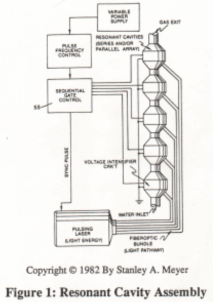
The Fuel-Cell is composed of Resonant Cavities pre-arranged to maximize Fuel-Energy delivery to the car engine, as illustrated in Figure 2 as to Figure 4.
Fuel-Gases / Quenching Tube 2×
-
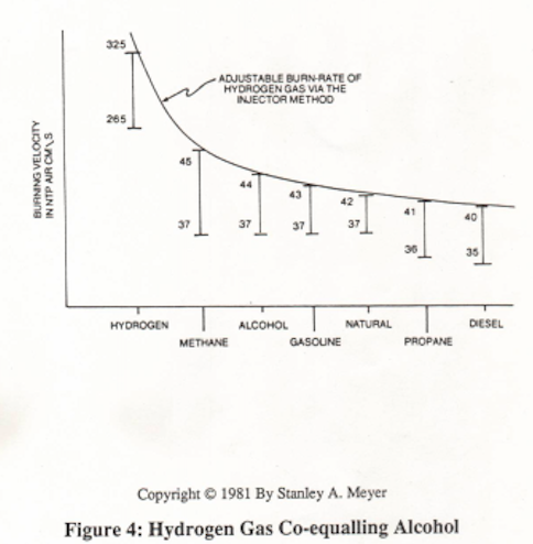
The Fuel-Cell Assembly of Figure (7) is directly retrofitted to the car engine without engine-change since the patented Hydrogen Gas-Mixture co-equals the burn-rate of Alcohol (from 325cm/sec. to 44 cm/sec.), as illustrated in Figure 4 as to Figure 5.
-
Figure 4