(20) · also written as a run, 20a xxx 20n
Laser Accelerator Assembly
Also written Water Fuel Injector · WFC Injector Assemblies · Additional WFC Injector Assemblies · Water Fuel Injector Plug · Laser Accelerator · Water Fuel Injectors · cluster array
Where it is first named
Laser Accelerator Circuit (10) of Figure (4) which is a component part of Laser Accelerator Assembly (20) of Figure (3-10) uses a GaAs infrared emitting diode (1) of figure (3-9) to trigger a SDP8611 Optoschmitt light receiver (2) of Figure (3-9) from quiescent state ( output logic high ... …
How it is written
- (20) 15×
- (20/30) 3× with (30) Circuit
- (20a xxx 20n) 2×
- (20 / 30) 1× with (30) Circuit
- (20a xxx 2On) 1× with (2O) Cluster Array
20a xxx 20n is Meyer's shorthand for a run of the same thing: 20a is the first, 20n the last, and the x's stand for however many lie between. Every stage of the run is this one numeral. A pair before the letters, 583/602a, is a run of two things that go together, one of each per stage.
Drawings 68
-
Stanley A. Meyer Page_6 of 28 · WFC 417 — WFC 417
-
Stanley A. Meyer Page17 of 28 · WFC 417 — WFC 417
-
Page 20 · WFC 417 — WFC 417
-
Stanley A. Meyer Page 20 of 28 · WFC 417 — WFC 417
-
Stanley A. Meyer Page. 23 of 28 · WFC 417 — WFC 417
-
Stanley A. Meyer Page 25 of 28 · WFC 417 — WFC 417
-
Stanley A. Meyer Page 28 of 28° · WFC 417 — WFC 417
-
Laser activated or laser primed gas ions repel the "dislodged" electrons being consumed as illustrated in Figure (1-8) as to Figure (1-20). · Electron Extraction Process
-
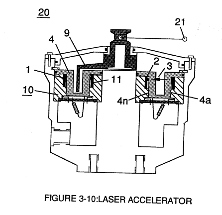
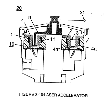
Light-gate (9) integrated with led pickup circuit (10) make up Laser Accelerator assembly (20), as shown in Figure (3-10). · Laser Accelerator Assembly
-
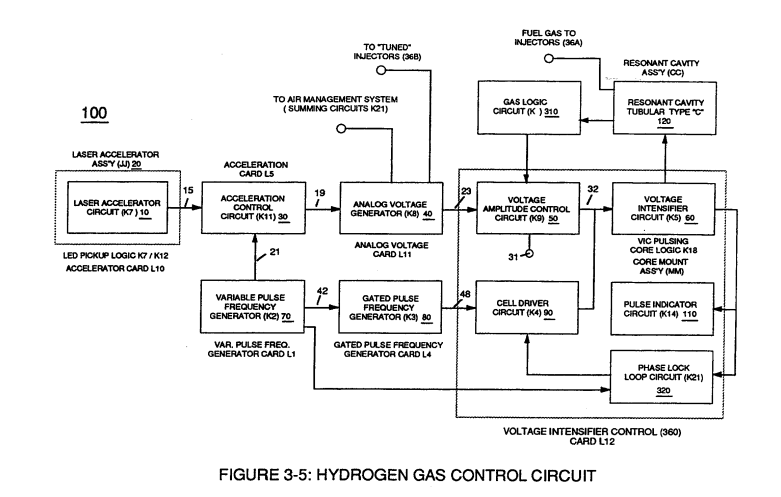
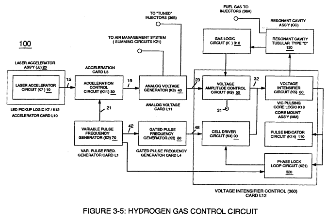
Figure (3-5) · Acceleration Control Circuit (30)
-
Analog Voltage Circuit (40), as shown in Figure (3-5) · Acceleration Control Circuit (30)
-
Figure (3-5) · Acceleration Control Circuit (30)
-
Figure (3-5) · Analog Voltage generator (40)
-
Figure (3-20) · Voltage Intensifier Circuit (60)
-
Laser Accelerator (20) of Figure (3-10) · Laser Distributor
-
Figure (3-2) · Laser Distributor
-
Figure (3-5) · Laser Distributor
-
Water Fuel Injector Plug (40) of Figure (4-2) · Operational Parameters
-
Carries this number · WFC 422DA - Illustrations
-
Carries this number · WFC 422DA - Illustrations
-
Carries this number · WFC 422DA - Illustrations
-
Carries this number · WFC 422DA - Illustrations
-
Carries this number · Water Fuel Injection System
-
3-4 Inner Core Bobbin · Voltage Intensifier Coil Assembly
-
3-5 Outer Core Bobbin · Voltage Intensifier Coil Assembly
-
Carries this number · Voltage Intensifier Coil Assembly
-
Carries this number · Voltage Intensifier Coil Assembly
-
Carries this number · Electronic Circuit Design
-
Carries this number · Electronic Circuit Design
-
Carries this number · Electronic Circuit Design
-
Carries this number · Electronic Circuit Design
-
Carries this number · Electronic Circuit Design
-
Carries this number · Differential Air-Gas Inlet Control
-
Water Fuel Injection System (10) of Figure (1) · Water Fuel Injector (Taper Resonant Cavity Chamber)
-
(170) of Figure (13) · Water Fuel Injector (Taper Resonant Cavity Chamber)
-
(170) of Figure (13) · Water Fuel Injector (Taper Resonant Cavity Chamber)
-
Fluid Displacement Pump (170) of Figure (13) · Water Fuel Injector (Taper Resonant Cavity Chamber)
-
Carries this number · Water Fuel Injector (Taper Resonant Cavity Chamber)
-
2-3 Water Inlet Housing · Water Fuel Injector Illustrations
-
2-5 Clamp Nut Assembly · Water Fuel Injector Illustrations
-
WFC Injector Assemblies (20) of Figure (4-1) · Water Fuel Injection System - Page 3
-
...converts water mist (68) into it's component gases hydrogen (77 a/b) oxygen (76) and ambient air gases (97); · Triggering Process
-
Figure (5-6) · Energy Recycling Spectrum
-
(760) of Figure (7-15) · Inductance (FL)
-
(532) of Figure (5-6) · Capacitance (Cd)
-
Carries this number · Multi-layer Coil
-
(760) of Figure (7-15) · Circuit Resistance
-
... each bobbin cavity adhering to equation (Eq 20), as illustrated in (710) of Figure (7-10). · Transformer Action
-
Carries this number · WFC 426 - Illustrations
-
Carries this number · 8-1 - Propagating "Resonant Action" By Voltage Tickling of State Space
-
Carries this number · WFC 428 - Illustrations
-
reciprocating WFC Fuel-kits can be similar to Car design (340); · Aviation Application
-
reciprocating WFC Fuel-kits can be similar to Car design (340); · Aviation Application
-
The figure it sits on · Electronic Circuit Design
-
The figure it sits on · Electronic Circuit Design
-
(220) of Figure (18) · Water Fuel Injector (Taper Resonant Cavity Chamber)
-
The figure it sits on · Water Fuel Injector (Taper Resonant Cavity Chamber)
-
The Following Page 1-7 was not available · Water Fuel Injector (Taper Resonant Cavity Chamber)
-
Figure (4-2) · Water Fuel Injection System - Page 1
-
Figure (4-12) · Water Fuel Injection System - Page 3
-
which simply uses Water Fuel Management (WFMS) System fluid-metering system (40) to control gas ignition (16), as illustrated in (40) of Figure (4-2). · Water Fuel Injection System - Page 4
-
(40) of Figure (4-2) · 8-5 - Energy Vectoring (Ev)
-
"FullSystem" development (10) of Figure (4-1) · WFC Development Objectives
-
Figure (10-3 A/B) · Propagating Electrical Stress
-
The figure it sits on · WFC 429 - Illustrations
-
The figure it sits on · WFC 429 - Illustrations
-
The figure it sits on · WFC 429 - Illustrations
-
The figure it sits on · Wobbling Effect
Where it is named · 22
Laser Accelerator Assembly 5×
-
Laser Accelerator Assembly (20)
Laser Accelerator Circuit (10) of Figure (4) which is a component part of Laser Accelerator Assembly (20) of Figure (3-10) uses a GaAs infrared emitting diode (1) of figure (3-9) to trigger a SDP8611 Optoschmitt light receiver (2) of Figure (3-9) from quiescent state ( output logic high ... …
-
Laser Accelerator Assembly (20)
Laser Accelerator Assembly (20) of Figure (3-10)
-
Grouping additional optical circuits (8a xxx 8n) in an inline or linear arrangement, now, forms Led Pickup Circuit (10) of Figure (3-9), as shown in Figure assembly (20) of Figure (3-10).
-
Figure assembly (20) of Figure (3-10)
-
Laser Accelerator assembly (20)
Light-gate (9) integrated with led pickup circuit (10) make up Laser Accelerator assembly (20), as shown in Figure (3-10).
Acceleration Control Circuit (30) 1×
-
Laser Accelerator Assembly (20)
… xxI4n) or signal output (15) of Figure (3-5) is, now, electrically transmitted to Acceleration Control Circuit (30) of Figure (3-5) since Laser Accelerator Assembly (20) of figure (3-10) converts mechanical displacement (9a xxx 9n) to electrical time-response (14a xxx 14n) of Figure (3-7) by linearly moving (forward and/or reverse direction) "low" logic state signal …
Voltage Amplitude Control Circuit (50) 1×
-
Laser Accelerator Assembly (20)
In terms of operability, Laser Accelerator Assembly (20) of Figure (3-5) is, now, attenuating battery voltage potential (32a xxx 32n) which is electrically connected to Voltage Intensifier Circuit (60) of Figure (3-5).
Laser Distributor 2×
-
Laser Accelerator (20)
Laser Distributor assembly (430) of Figure (3-44) functions in similar manner as Laser Accelerator (20) of Figure (3-10) except light-gate (141) of Figure (3-44) rotates in the same direction of Spark-rotor (142) and being displaced opposite to rotor blade (142), allowing intermixed processed ambient a …
Water Fuel Injection System 4×
-
Additional WFC Injector Assemblies (20)
Additional WFC Injector Assemblies (20) of Figure (2) are arranged in cluster array (20a xxx 20n) to increase energy-yield output (16a xxx 16n) of Figure (10 / 1 / 12).
-
Additional WFC Injector Assemblies (20) of Figure (2) are arranged in cluster array (20a xxx 20n) to increase energy-yield output (16a xxx 16n) of Figure (10 / 1 / 12).
-
Water Fuel Injector (20/30)
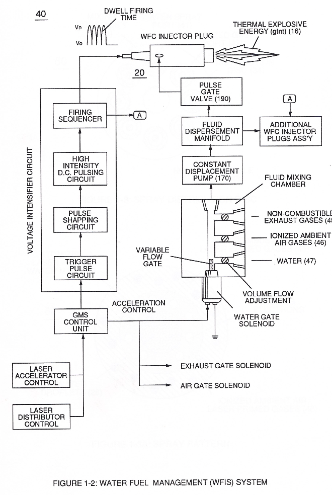
Sequential pulsing of Water Fuel Injector (20/30) of Figure (1) as to (40) of Figure (2B) is system activated by Pulse Gate Valve (190) of Figure (1) to further control a predetermined energy-flame (16).
-
Water Fuel Injector Plug (20 / 30)
Water Fuel Injector Plug (20 / 30), as illustrated in (40) of Figure (2B) as to (10) of Figure (1).
Funneling Effect 2×
-
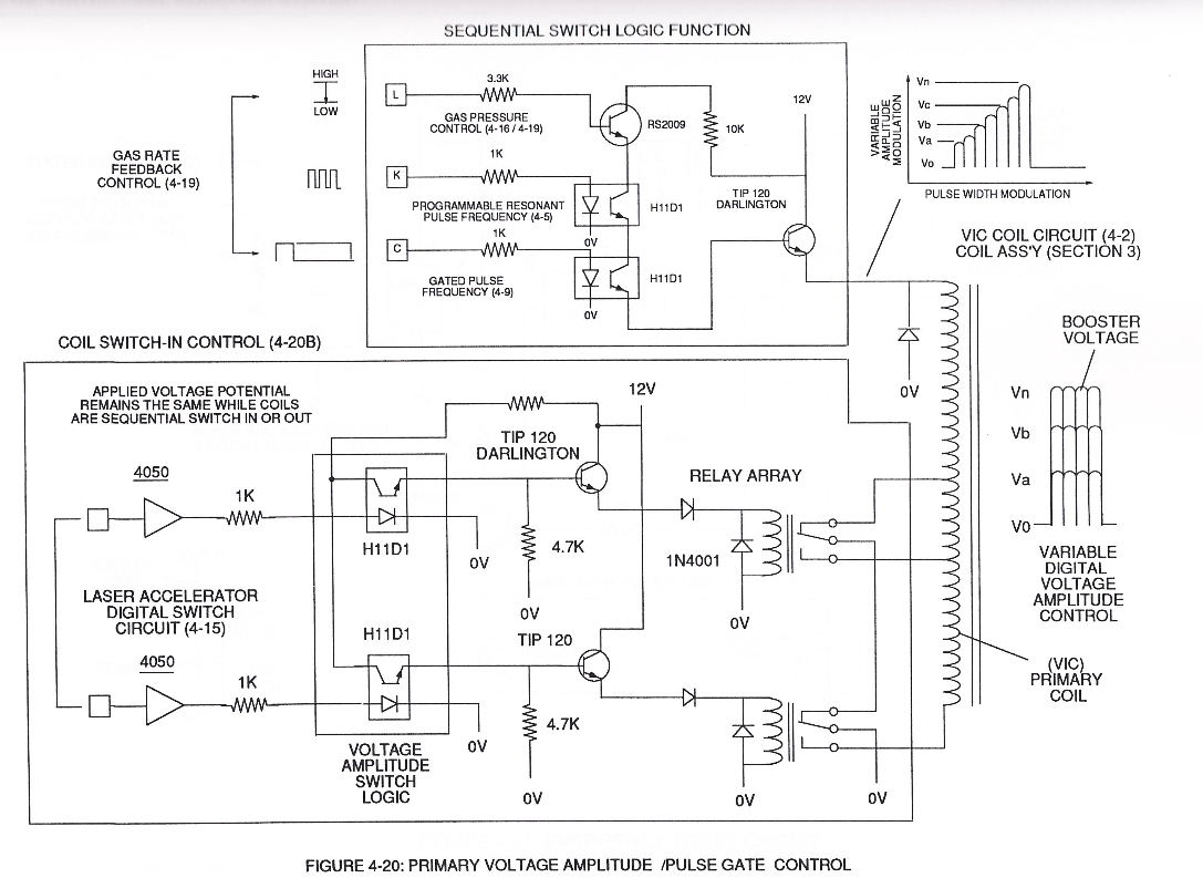
… "Electrical Force" (Vma xxx Vmn) which is due to the inductance/capacitance values of each succeeding coil-structure (61a x 61n) forming Booster coil-Assembly (250), as illustrated in (240) of Figure (20).
-
… f" each adjacent coil-stage (61a xxx 61n) by "Shunting" or "Redirecting" induced voltage intensity (Vmn xxx Vma) to its respective electrical out-put leads (72n - 72c - 72b - 72a), as shown in Figure (20).
Water Fuel Injection System - Page 3 3×
-
WFC Injector Assemblies (20)
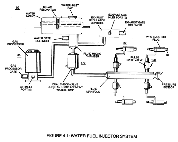
Additional WFC Injector Assemblies (20) of Figure (4-1) are arranged in cluster array (20a xxx 2On) to increase energy-yield output (16a xxx 16n) of Figure (4-12/4-13/4-14).
-
cluster array (20a xxx 2On)
Additional WFC Injector Assemblies (20) of Figure (4-1) are arranged in cluster array (20a xxx 2On) to increase energy-yield output (16a xxx 16n) of Figure (4-12/4-13/4-14).
-
WFC Injector Assemblies (20)
WFC Injector Assemblies (20) of Figure (4-1)
Water Fuel Injection System - Page 4 2×
-
Water Fuel Injector (20/30)
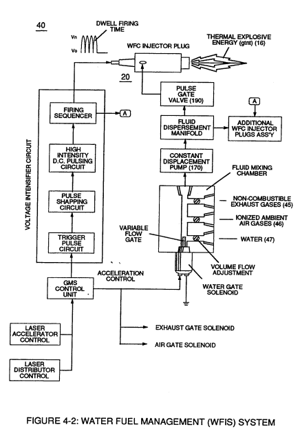
Sequential pulsing of Water Fuel Injector (20/30) of Figure (4-1) as to (40) of Figure (4-2) is system activated by Pulse Gate Valve (190) of Figure (4-1) to further control a predetermined energy-flame (16).
-
Water Fuel Injector Plug (20/30)
... especially when ionized ambient air gases (400 xxx 46n) and non-combustible gases (45a xxx 45n) are intermixed with water supply (47) prior to entering Water Fuel Injector Plug (20/30), as illustrated in (40) of Figure (4-2) as to (10) of Figure (4-1).
Taper Water Fuel Injectors 2×
-
Water Fuel Injector (20)
Basically, then, activation process (590), now, design - forms Water Fuel Injector (20) of Figure (4-2) as to (30) of Figure (4-11) (Memo WFC 423 DA)
-
Water Fuel Injectors (20a xxx 20n)
... allowing Water Fuel Injectors (20a xxx 20n) to replace standard Internal Combustion Engine spark-plugs and fossil-fuel injector ports, as graphically illustrated in Figure (140) of Figure (4-12) titled "Furnace Retrofit," (150) of Figure (4-13) titled "Jet Engine retrofit," and (160) of Figure (4-14) titled "Rocket Engines Retrofit."