(V0)
Voltage Amplitude
Also written applied voltage amplitude · pulse voltage amplitude
Where it is first named
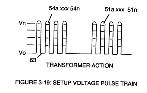
Analog voltage signal (32a xxx 32n) of Figure (3-15) allows pulse train (51a xxx 51n) voltage amplitude (V0 xxx Vn) of Figure (3-19) to vary from one up to twelve volts (battery supply 28 of Figure 3-6 by attenuating Laser Accelerator circuit (10) of Figure (3-5) via Hydrogen Gas Control Circuit (100).
How it is written
- (V0 xxx) 1×
- (V0 xxx Vn) 1× with (V) Voltage Amplitude
- (V0 xxx Vo) 1× with (Vo) Applied Voltage Amplitude
- (xxx V0) 1×
Drawings 16
-
Figure (3-19) · Cell Driver Circuit (90)
-
Figure (3-19) · Voltage Intensifier Circuit (60)
-
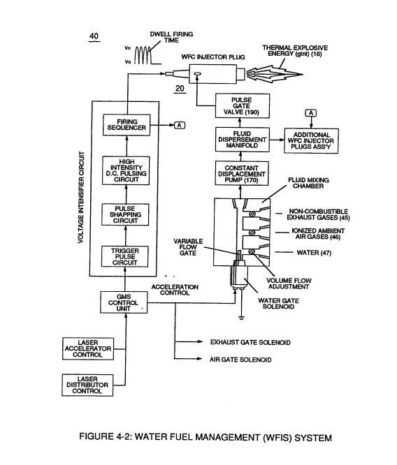
Water Fuel Injector Plug (40) of Figure (4-2) · Operational Parameters
-
The figure it sits on · WFC 422DA - Illustrations
-
(220) of Figure (18) · Water Fuel Injector (Taper Resonant Cavity Chamber)
-
The figure it sits on · Water Fuel Injector (Taper Resonant Cavity Chamber)
-
The Following Page 1-7 was not available · Water Fuel Injector (Taper Resonant Cavity Chamber)
-
Figure (4-2) · Water Fuel Injection System - Page 1
-
which simply uses Water Fuel Management (WFMS) System fluid-metering system (40) to control gas ignition (16), as illustrated in (40) of Figure (4-2). · Water Fuel Injection System - Page 4
-
The figure it sits on · 8-1 - Propagating "Resonant Action" By Voltage Tickling of State Space
-
(40) of Figure (4-2) · 8-5 - Energy Vectoring (Ev)
-
Figure (10-3 A/B) · Propagating Electrical Stress
-
The figure it sits on · WFC 429 - Illustrations
-
The figure it sits on · WFC 429 - Illustrations
-
The figure it sits on · WFC 429 - Illustrations
-
The figure it sits on · Wobbling Effect
Where it is named · 4
Voltage Intensifier Circuit (60) 1×
-
voltage amplitude (V0 xxx Vn)
Analog voltage signal (32a xxx 32n) of Figure (3-15) allows pulse train (51a xxx 51n) voltage amplitude (V0 xxx Vn) of Figure (3-19) to vary from one up to twelve volts (battery supply 28 of Figure 3-6 by attenuating Laser Accelerator circuit (10) of Figure (3-5) via Hydrogen Gas Control Circuit (100).
Water Fuel Injection System - Page 2 3×
-
applied voltage amplitude (V0 xxx Vo)
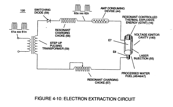
To elevate Energy-flame-temperature still further, simply increase fluid-displacement (46/47) while maintaining or reducing the volume flow rate of non-combustible gases (45) during an increase of applied voltage amplitude (V0 xxx Vo) of Figure (4-2) as to Voltage Intensifier Circuit (110) of Figure (4-9) and Electron Extraction Circuit (120) of Figure (4-10).
-
pulse voltage amplitude (xxx V0)
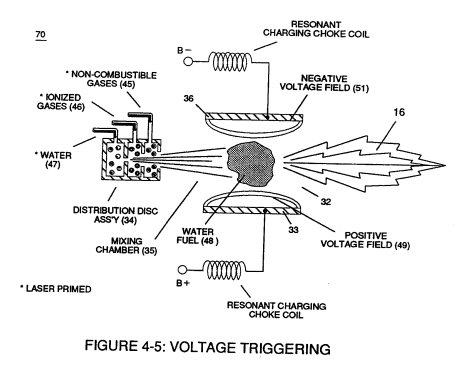
To lower Energy-flame temperature simply increase the amount of non-combustible gases (45a xxx) or reduced the fluid flow rate (45 / 46 / 47) uniformly while lowering pulse voltage amplitude (xxx V0).
-
voltage amplitude (V0 xxx)
To establish a predetermined or given Energy-flame temperature adjust fluid-medium (45 / 46 / 47) and applied voltage amplitude (V0 xxx) independent of each other to obtain the desired results.