(SS56) · also written as a run, SS56a xxx SS56n
Resonant Charging Chokes Stages
Also written Stainless Steel bifilar-coil · Stainless Steel coil-wire · bifilar coil assembly · Coil-Stage Assembly · SS Coil-Wire · Coil Stages
Where it is first named
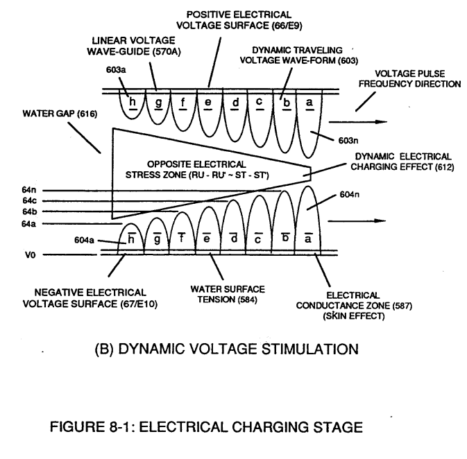
… Figure (8-1) is simply produced when Programmable Variable Pulse-Width Pulse-Train Waveform (49a xxx 49n) is allowed to be electrically transmitted through and beyond Resonant Charging Chokes Stages (56/62a xx 56/62n + SS56/62a xxx SS56/62n) of Figure (10-4) that are not only electrically connected in sequential order but likewise magnetically linked by Inductance Coupling field (511/512a xxx 511/512n), as so pictorially illustrated in ( …
How it is written
- (SS56/62) 2× with (62) Resonant Charging Chokes
- (56/62a xxx 56/62n + SS56/62a xxx SS56/62) 1× with (56) Resonant Charging Choke, (62) Resonant Charging Chokes
- (56/62a xxx 56/62n -S- SS56/62a xxx SS56/62n) 1× with (56) Resonant Charging Choke, (62) Resonant Charging Chokes
- (56/62a xx 56/62n + SS56/62a xxx SS56/62n) 1× with (56) Resonant Charging Choke, (62) Resonant Charging Chokes
- (SS56/62a xxx SS56/62n) 1× with (62) Resonant Charging Chokes
- (SS56-SS62) 1× with (SS62) Stainless Steel coil-wire
- (56/62 - SS56/62) 1× with (56) Resonant Charging Choke, (62) Resonant Charging Chokes
SS56a xxx SS56n is Meyer's shorthand for a run of the same thing: SS56a is the first, SS56n the last, and the x's stand for however many lie between. Every stage of the run is this one numeral. A pair before the letters, 583/602a, is a run of two things that go together, one of each per stage.
Drawings 28
-
(270) of Figure (3-34) · Gas Processor
-
The figure it sits on · WFC 422DA - Illustrations
-
(270) of (3-34) · In Application of Usage
-
The figure it sits on · VIC Matrix Circuit
-
(T2) of Figure (7-8) · Instant Explosion of Water
-
Figure (7-8) · Resistance (Rs)
-
(690) of Figure (7-8) · Resistance (Rs)
-
(690) of Figure (7-8) · Inductance (FL)
-
(690) of Figure (7-8) · Capacitance (Cd)
-
(690) of Figure (7-8) · Inductance Reactance (Rs - Cd - FL)
-
Figure (7-8) · Inductance Reactance (Rs - Cd - FL)
-
(690) of Figure (7-8) · Taper Resonant Capacitor (ERt)
-
690 of Figure 7-8 · Circuit Resistance
-
(52) of Figure (7-8) · Electron Bounce Phenomenon
-
(690) of Figure (7-8) · 8-2 - Traveling Voltage Wave-Guides
-
(52) of Figure (7-8) · 8-3 - Electrical Voltage-Pulse Wave-Transmission
-
(Cp) of Figure (7-8) · 8-4 - State Space (Sp)
-
(690) of Figure (7-8) · 8-6 - VIC Voltage Sync-Pulse Circuit
-
(Cp) of (7-8) · 8-6 - VIC Voltage Sync-Pulse Circuit
-
(690) of Figure (7-8) · Propagating Electrical Stress
-
Figure (3-34) · Propagating Electrical Stress
-
(990) of Figure (10-3) · Propagating Electrical Stress
-
The figure it sits on · Voltage to Amp Differential Ratio
-
Figure (10-3) · Voltage to Amp Differential Ratio
-
blocking diode (55) of Figure (3-34) · Voltage to Amp Differential Ratio
-
The figure it sits on · WFC 429 - Illustrations
-
The figure it sits on · WFC 429 - Illustrations
-
voltage intensifier circuit (990) of Figure (10-3) · VIC Switchover Circuit
Where it is named · 8
Voltage to Amp Differential Ratio 8×
-
Resonant Charging Chokes Stages (56/62a xx 56/62n + SS56/62a xxx SS56/62n)
… Figure (8-1) is simply produced when Programmable Variable Pulse-Width Pulse-Train Waveform (49a xxx 49n) is allowed to be electrically transmitted through and beyond Resonant Charging Chokes Stages (56/62a xx 56/62n + SS56/62a xxx SS56/62n) of Figure (10-4) that are not only electrically connected in sequential order but likewise magnetically linked by Inductance Coupling field (511/512a xxx 511/512n), as so pictorially illustrated in ( …
-
bifilar coil assembly (56/62a xxx 56/62n -S- SS56/62a xxx SS56/62n)
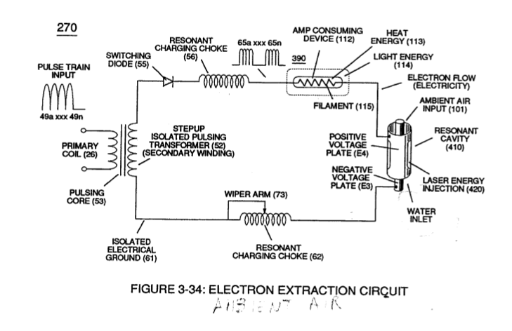
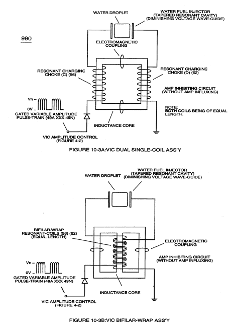
... allowing each/both bifilar coil assembly (56/62a xxx 56/62n -S- SS56/62a xxx SS56/62n) to be electrically and magnetically energized in the same progressive direction toward Water Gap (Cp) and away from blocking diode (55) of Figure (3-34) as to Figure (10-1) and Figure (10-3)
-
Coil-Stage Assembly (SS56/62a xxx SS56/62n)
Stainless Steel bifilarCoil-Stage Assembly (SS56/62a xxx SS56/62n) is electrically placed between Magnet Coil-Stage Assembly (56/62a xxx 56/62n) and Water Gap (Cp) to obtain optimum Voltage to Amp Differential Ratio (Vhighest:Alowest ratio).
-
Coil Stages (56/62a xxx 56/62n + SS56/62a xxx SS56/62)
Together, Coil Stages (56/62a xxx 56/62n + SS56/62a xxx SS56/62) added/stacked sequentially into a single overall coil-array assembly (990A/B) of Figure (10-3) forms Amp Inhibiting Network (Figure 8XA) as to (970) of Figure (10-1) (hereinafter called VIC Multi-Coil Spool Assembly).
-
Stainless Steel coil-wire (SS56-SS62)
The magnet Coil-Wire (56/62) is best suited for Voltage inducement while the inductance/capacitance/resistance properties of Stainless Steel coil-wire (SS56-SS62) is appropriately used to restrict electron movement beyond the self-inductance of each energized coil when elevated voltage levels (up to beyond 40 kilovolts) are to be reached/obtained without experiencing any appreciable amount of "Amp Influxing."
-
Stainless Steel bifilar-coil (SS56/62)
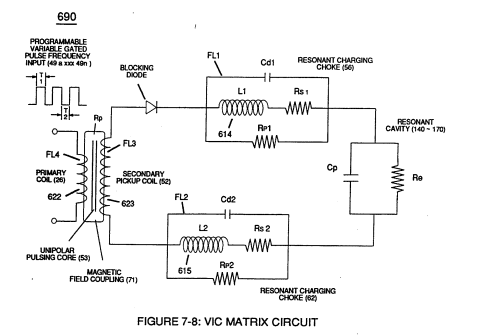
Generally, magnet coil-wire length is longer than the Stainless steel coil-wire length and magnet bifilar-coil (56/62) is placed on top of Stainless Steel bifilar-coil (SS56/62) to maximize mutual inductance coil-field (Rp2) (adding Rp1+Rp2) of (690) of Figure (7-8) to cause coil capacitance (Cda xxx Cdn) to help maintain and even increase pulse voltage amplitude (xxx Vn + Vn 1 + Vn2 + Vn .... …
-
SS Coil-Wire (SS56/62)
… etc.) while the resistive value (Rs2) of SS Coil-Wire (SS56/62) performs the work of further resisting the flow of amps not inhibited by both self-Inductance fields (Rpl + Rp2), as so illustrated in (690) of Figure (7-8).
-
In all cases, bifilar coils (56/62 - SS56/62) are electromagnetically orientated in the same direction.