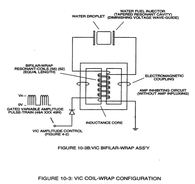
Figure (10-3)
Figure (10-3)
How it is written
- (10-3) 7×
Drawings 3
-
(990) of Figure (10-3) · Propagating Electrical Stress
-
Figure (10-3) · Voltage to Amp Differential Ratio
-
voltage intensifier circuit (990) of Figure (10-3) · VIC Switchover Circuit
On this figure 10
- 56 Resonant Charging Choke
- 62 Resonant Charging Chokes
- 952 Stationary Voltage Fields
- 953 Stationary Voltage Fields
- 957 Primary Input Coil
- 958 Negative Voltage Field
- 990 Voltage Intensifier Circuit
- 990A —
- 990B —
- SS56 Resonant Charging Chokes Stages
Where it is named · 7
Propagating Electrical Stress 2×
-
… age input since the "Distributed Capacitance" (C1a xxx C1n - C2a xxx C2n) / "Distributed Inductance" (FL1a xxx FL1n - FL2a xxx FL2n) of said "bifilar" wrapped coils (Figure 7-3) as to (990) of Figure (10-3) encourages the compounding effect (increasing magnetic field-strength during each pulsing cycle) of electromagnetic field-strength (Rp1a xxx Rp1n - Rp2a xxx Rp2n) (mutual induction) when applied Puls …
-
(990) of Figure (10-3)
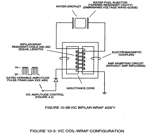
Voltage to Amp Differential Ratio 3×
-
... allowing each/both bifilar coil assembly (56/62a xxx 56/62n -S- SS56/62a xxx SS56/62n) to be electrically and magnetically energized in the same progressive direction toward Water Gap (Cp) and away from blocking diode (55) of Figure (3-34) as to Figure (10-1) and Figure (10-3)
-
Figure (10-3)
-
Together, Coil Stages (56/62a xxx 56/62n + SS56/62a xxx SS56/62) added/stacked sequentially into a single overall coil-array assembly (990A/B) of Figure (10-3) forms Amp Inhibiting Network (Figure 8XA) as to (970) of Figure (10-1) (hereinafter called VIC Multi-Coil Spool Assembly).
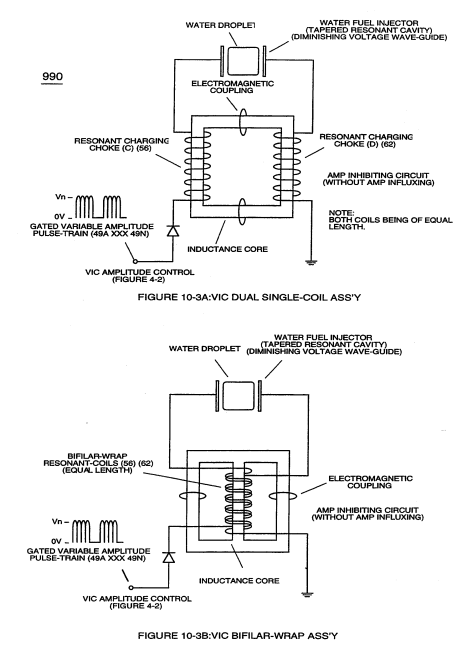
VIC Switchover Circuit 2×
-
voltage intensifier circuit (990) of Figure (10-3)