Figure (3-10)
Laser Accelerator
How it is written
- (3-10) 15×
Drawings 4
-
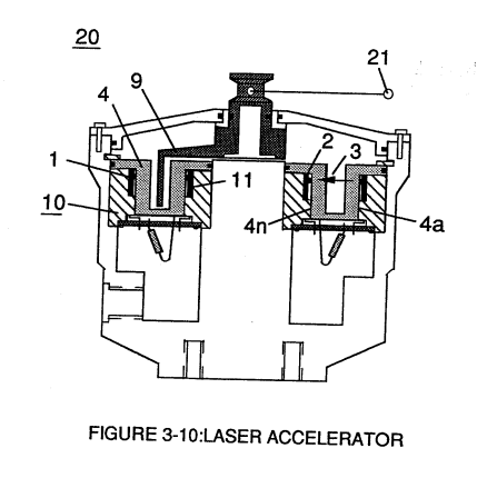
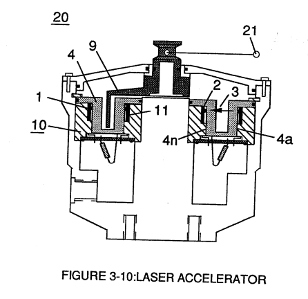
Light-gate (9) integrated with led pickup circuit (10) make up Laser Accelerator assembly (20), as shown in Figure (3-10). · Laser Accelerator Assembly
-
Laser Accelerator (20) of Figure (3-10) · Laser Distributor
-
Captioned as this figure · WFC 422DA - Illustrations
-
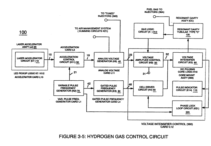
Analog Voltage Circuit (40), as shown in Figure (3-5) · Acceleration Control Circuit (30)
On this figure 7
- 2 Optoschmitt
- 4 Electrical Tension
- 9 Light-Gate
- 10 Led Pickup Circuit
- 20 Laser Accelerator Assembly
- 21 Resonant Action
- 22 Compounding Action
Where it is named · 15
Laser Accelerator Assembly 11×
-
Laser Accelerator Assembly (20) of Figure (3-10)
-
Optical lens (4) of Figure (310) redirects and focuses the transmitted light source (3) of Figure (3-9) (traveling infrared light waves) to the Optoschmitt (2) by passing the light source through a series of concentric lenses (4a xxx 4n) of Figure (3-10) which become progressively smaller from the outer peripheral lens surface (4a) to the inner lens surface (4n).
-
The spatially concentric lenses (4a xxx 4n) of Figure (3-10) causes the beam angle of the light source to trigger the Optoschmitt (2) beyond the minimum irradiance that is needed to switch the Optoschmitt from quiescent state (high logic state I B+ ) to on-state (output changing to zero volts).
-
The Derate linearly of light intensity is approximately 1.25mWj degree C above 25 degree C at a spatial distance of .500 inches between the two infrared devices (1)(2) of Figure (3-9) as to Figure (3-10).
-
Grouping additional optical circuits (8a xxx 8n) in an inline or linear arrangement, now, forms Led Pickup Circuit (10) of Figure (3-9), as shown in Figure assembly (20) of Figure (3-10).
-
Figure assembly (20) of Figure (3-10)
-
To perform a switch-logic function, light - gate (9) of Figure (3-9) as to Figure (3-10) is inserted between the matched infrared devices (1)(2) and moved in a linear displacement from one optical circuit (8x) to another optical circuit (8xx), as illustrated in Figure (3-9)(3-10) as to Figure (3-7).
-
To perform a switch-logic function, light - gate (9) of Figure (3-9) as to Figure (3-10) is inserted between the matched infrared devices (1)(2) and moved in a linear displacement from one optical circuit (8x) to another optical circuit (8xx), as illustrated in Figure (3-9)(3-10) as to Figure (3-7).
-
Light-gate (9) of Figure (3-10) is mechanically linked to the car acceleration pedal by way of cabling hookup (22).
Acceleration Control Circuit (30) 2×
-
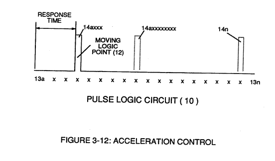
… xxI4n) or signal output (15) of Figure (3-5) is, now, electrically transmitted to Acceleration Control Circuit (30) of Figure (3-5) since Laser Accelerator Assembly (20) of figure (3-10) converts mechanical displacement (9a xxx 9n) to electrical time-response (14a xxx 14n) of Figure (3-7) by linearly moving (forward and/or reverse direction) "low" logic state signal (12) in a array o …
-
In retrospect to engine performance (gas pedal attenuation) (21) of Figure (3-10), a wider pulse width (17a xxx) of Figure (3-13C) increases (accelerates) engine R.P.M.; whereas, smaller pulse-width (17ax) reduces (de-accelerates) engine R.P.M .. Cruising speed (3-13B) of Figure (3-13) is simply accomplished when pulse width remains constant.
Laser Distributor 2×
-
Laser Distributor assembly (430) of Figure (3-44) functions in similar manner as Laser Accelerator (20) of Figure (3-10) except light-gate (141) of Figure (3-44) rotates in the same direction of Spark-rotor (142) and being displaced opposite to rotor blade (142), allowing intermixed processed ambient air gases (101) an …
-
Laser Accelerator (20) of Figure (3-10)