(21) · also written as a run, 21a xxx 21n
Resonant Action
Also written clock signal · clock pulse
Where it is first named
In retrospect to engine performance (gas pedal attenuation) (21) of Figure (3-10), a wider pulse width (17a xxx) of Figure (3-13C) increases (accelerates) engine R.P.M.; whereas, smaller pulse-width (17ax) reduces (de-accelerates) engine R.P.M .. Cruising speed (3-13B) of Figure (3-13) is simply accomplished when pulse width remains constant.
How it is written
- (21) 6×
- (21a xxx 21n) 1×
21a xxx 21n is Meyer's shorthand for a run of the same thing: 21a is the first, 21n the last, and the x's stand for however many lie between. Every stage of the run is this one numeral.
Drawings 36
-
Stanley A. Meyer Page 21 of 28 · WFC 417 — WFC 417
-
Carries this number · Rocket Propulsion
-
Light-gate (9) integrated with led pickup circuit (10) make up Laser Accelerator assembly (20), as shown in Figure (3-10). · Laser Accelerator Assembly
-
Figure (3-16) · Acceleration Control Circuit (30)
-
Figure (3-21) · Voltage Amplitude Control Circuit (50)
-
Figure (3-16) · Variable Pulse Frequency Generator (70)
-
Figure (3-21) · Voltage Intensifier Circuit (60)
-
Carries this number · Voltage Dynamics
-
Carries this number · Gas Processor
-
Laser Accelerator (20) of Figure (3-10) · Laser Distributor
-
Carries this number · Laser Distributor
-
Carries this number · WFC 422DA - Illustrations
-
Carries this number · WFC 422DA - Illustrations
-
Carries this number · WFC 422DA - Illustrations
-
Carries this number · Electronic Circuit Design
-
Carries this number · Electronic Circuit Design
-
Carries this number · Electronic Circuit Design
-
Carries this number · Electronic Circuit Design
-
Carries this number · Electronic Circuit Design
-
Carries this number · Cover Page
-
laser primed ionized liquid oxygen (68) of Figure (1-21) · Water Fuel Injection System - Page 3
-
Carries this number · Taper Resonant Capacitor (ERt)
-
Figure (3-5) · Acceleration Control Circuit (30)
-
Analog Voltage Circuit (40), as shown in Figure (3-5) · Acceleration Control Circuit (30)
-
Figure (3-5) · Acceleration Control Circuit (30)
-
Figure (3-5) · Analog Voltage generator (40)
-
Figure (3-5) · Laser Distributor
-
The figure it sits on · WFC 422DA - Illustrations
-
3-5 Outer Core Bobbin · Voltage Intensifier Coil Assembly
-
3-16 Mount Bar · Voltage Intensifier Coil Assembly
-
The figure it sits on · Differential Air-Gas Inlet Control
-
Figure (5-5) · Resonant Propagation
-
The figure it sits on · Illustrations
-
(90) of Figure (5-5) · Capacitance Reactance
-
... causing "electron clustering" (641a xxx 641n) to take place within Copper Wire Zone (52) during pulse on- time (T1) · Electron Bounce Phenomenon
-
(90) of Figure (5-5) · 8-2 - Traveling Voltage Wave-Guides
Where it is named · 7
Acceleration Control Circuit (30) 3×
-
In retrospect to engine performance (gas pedal attenuation) (21) of Figure (3-10), a wider pulse width (17a xxx) of Figure (3-13C) increases (accelerates) engine R.P.M.; whereas, smaller pulse-width (17ax) reduces (de-accelerates) engine R.P.M .. Cruising speed (3-13B) of Figure (3-13) is simply accomplished when pulse width remains constant.
-
clock pulse (21a xxx 21n)
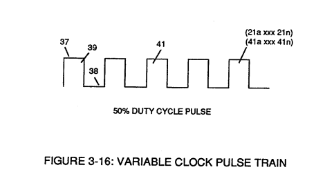
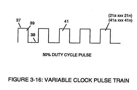
Incoming clock pulse (21a xxx 21n) of Figure (3-16) originating from Pulse Frequency Generator (70) of
-
clock pulse (21)
The resultant clock pulse (21) of Figure (3-16) as to Figure (3-5) is always adjusted to exceed driver's response time to allow for instant acceleration control.
Variable Pulse Frequency Generator (70) 2×
-
clock signal (21)
Increasing the number of duty pulses (39a xxx 39n) up to pulse frequency range of 10Khz or above now forms clock signal (21) of Figure (3-5) which, in turns, performs the scanning function of Acceleration Control Circuit (30) of Figure (3-5).
-
clock signal (21)
In both cases, pulse frequency range of each clock signal (21) and (42) can be altered or change (controlled independent of each other) to obtain peak performance of Fuel Cell System (100) of Figure (3-5).
Resonant Propagation 2×
-
Resonant Action (21)
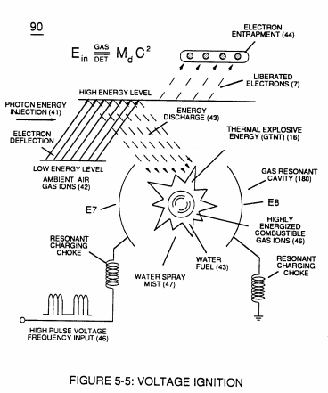
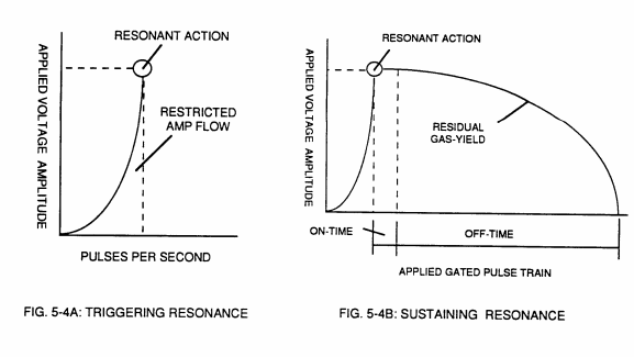
Resonant Action (21) (point of particle oscillation) occurs when applied pulse voltage frequency (46) of Figure (5-5) is adjusted to "tune-in" to the Dielectric Resonance of water via voltage Intensifier Circuit (60) of Figure (5 -3);
-
Resonant Action (21)
Resonant Action (21), Compounding Action (22), Laser Injection (17). and Energy Pumping Action (520), Now, allows the production of hydrogen and oxygen gases from water in geometrical progression to set up Hydrogen Fracturing Process (90). as illustrated in Figure (5-4C) as to Figure (5-5).