Figure (3-13)
Speed Control
Also written Flat-seal
How it is written
- (3-13) 8×
Drawings 4
-
Figure (3-13) · Acceleration Control Circuit (30)
-
Figure (3-13) · Acceleration Control Circuit (30)
-
Captioned as this figure · WFC 422DA - Illustrations
-
3-13 Flat Seal · Voltage Intensifier Coil Assembly
On this figure 7
- 9 Light-Gate
- 12 Logic-Point
- 14 Response-Time
- 16 Flame Projection
- 17 Pulse width
- 22 Compounding Action
- 30 Circuit
Where it is named · 8
Acceleration Control Circuit (30) 5×
-
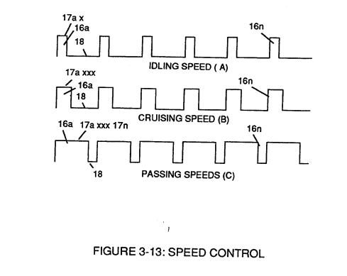
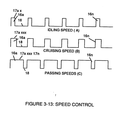
Circuit (30) continues to increase pulse width (17axxxx) of Figure (3-8) as the monitored (detected by < scanning) toggling-time (14a xxxx ... 12) increases when logic-point (12) moves farther away from start-position (9a) to stop-position (9n), as further shown in Figure (3-13) as to Figure (3-12).
-
Figure (3-13)
-
Figure (3-13)
-
In retrospect to engine performance (gas pedal attenuation) (21) of Figure (3-10), a wider pulse width (17a xxx) of Figure (3-13C) increases (accelerates) engine R.P.M.; whereas, smaller pulse-width (17ax) reduces (de-accelerates) engine R.P.M .. Cruising speed (3-13B) of Figure (3-13) is simply accomplished when pulse width remains constant.
Analog Voltage generator (40) 3×
-
The newly formed analog signal (22) of Figure (3-14) is a voltage level signal that varies continuously in both time and amplitude to produce a voltage level which is directly proportional to the physical change in pulse train (100 xxx 16n) of Figure (3-13).
-
Figure (3-13)
-
Widening pulse width to stop-position (17a xxxx 17n) of Figure (3-13) causes analog signal (22) to increase to higher voltages levels; whereas, analog voltage level (22) drops (become lower in value) in voltage level when pulse width decreases to start-position (17a).