(4) · also written as a run, 4a xxx 4n
Electrical Tension
Also written Optical lens · spatially concentric lenses · concentric lenses · atomic electrical attraction force · outer peripheral lens surface · Electrical Pressure · inner lens surface
Where it is first named
Optical lens (4) of Figure (310) redirects and focuses the transmitted light source (3) of Figure (3-9) (traveling infrared light waves) to the Optoschmitt (2) by passing the light source through a series of concentric lenses (4a xxx 4n) of Figure (3-10) which become progressively smaller from the outer peripheral lens surface (4a) to the inner lens surface (4n).
How it is written
- (4) 4×
- (4 / 5) 2×
- (4a xxx 4n) 2×
- (4a) 1×
- (4n) 1×
4a xxx 4n is Meyer's shorthand for a run of the same thing: 4a is the first, 4n the last, and the x's stand for however many lie between. Every stage of the run is this one numeral.
Drawings 69
-
Copyright © 1983 by Stanley A Meyer Stanley A. Meyer Page16 of 28 · WFC 417 — WFC 417
-
Newton's and Coulomb's Laws of electrical-force is used to combine or join atoms together by way of Covalent Bonding (opposite electrical forces) to form liquids, solids, or air. · ATOMIC INTERACTION TO VOLTAGE STIMULATION
-
The Resonant Frequency (F) of an LC circuit in series is given by (Eq 4) · LC Circuit
-
Figure (3-5) · Acceleration Control Circuit (30)
-
Figure (3-5) · Acceleration Control Circuit (30)
-
where Resonant frequency (63) of LC circuit in series is given by (Eq 4) · Voltage Intensifier Circuit (60)
-
Carries this number · Laser Distributor
-
Carries this number · WFC 422DA - Illustrations
-
Carries this number · Voltage Intensifier Coil Assembly
-
Carries this number · Voltage Intensifier Coil Assembly
-
3-14 WFC Voltage Ignition Wire · Voltage Intensifier Coil Assembly
-
3-15 VIC Mount Plate · Voltage Intensifier Coil Assembly
-
3-16 Mount Bar · Voltage Intensifier Coil Assembly
-
Carries this number · Electronic Circuit Design
-
Carries this number · Electronic Circuit Design
-
Carries this number · Electronic Circuit Design
-
Carries this number · Electronic Circuit Design
-
Carries this number · Electronic Circuit Design
-
Carries this number · Electronic Circuit Design
-
Carries this number · Electronic Circuit Design
-
Carries this number · Electronic Circuit Design
-
Carries this number · Electronic Circuit Design
-
Carries this number · Electronic Circuit Design
-
Carries this number · Electronic Circuit Design
-
Carries this number · Electronic Circuit Design
-
Carries this number · Electronic Circuit Design
-
Carries this number · Electronic Circuit Design
-
Carries this number · Electronic Circuit Design
-
Carries this number · Electronic Circuit Design
-
Carries this number · Electronic Circuit Design
-
Carries this number · Electronic Circuit Design
-
Carries this number · Electronic Circuit Design
-
Carries this number · Electronic Circuit Design
-
Carries this number · Electronic Circuit Design
-
Carries this number · Electronic Circuit Design
-
Carries this number · Electronic Circuit Design
-
Carries this number · Electronic Circuit Design
-
Carries this number · Electronic Circuit Design
-
(220) of Figure (18) · Water Fuel Injector (Taper Resonant Cavity Chamber)
-
Carries this number · Water Fuel Injector (Taper Resonant Cavity Chamber)
-
Carries this number · Water Fuel Injector (Taper Resonant Cavity Chamber)
-
Carries this number · Water Fuel Injector (Taper Resonant Cavity Chamber)
-
The Following Page 1-7 was not available · Water Fuel Injector (Taper Resonant Cavity Chamber)
-
thereby, attenuating voltage amplitude (voltage intensity) beyond Secondary Coil (53) voltage levels (71), as illustrated in (220) of Figure (18). · Funneling Effect
-
2-6 Ceramic Insert · Water Fuel Injector Illustrations
-
(160) of Figure (3-26) · Water Fuel Injection System - Page 1
-
Figure (7-3) · Inductance (FL)
-
(820B) of Figure (8-6) · 8-7 - Application of Usage
-
(820C) of Figure (8-6) · 8-7 - Application of Usage
-
Carries this number · WFC 427 Illustrations
-
(210) of Figure (3-27) · Electrovalent Bonding
-
Figure (10-3 A/B) · Propagating Electrical Stress
-
(990) of Figure (10-3) · Propagating Electrical Stress
-
The programmable pulse-frequency (49a xxx 49n) of Figure (10-1) input is simply adjusted to tune-in to the dielectric property of the Water Molecule. · Propagating Electrical Stress
-
Carries this number · Voltage to Amp Differential Ratio
-
Figure (10-3A) · Voltage to Amp Differential Ratio
-
Carries this number · WFC 429 - Illustrations
-
Carries this number · WFC 429 - Illustrations
-
Carries this number · WFC 429 - Illustrations
-
Carries this number · Wobbling Effect
-
(1030) of figure (11-3) · Voltage Flexing Process
-
voltage intensifier circuit (990) of Figure (10-3) · VIC Switchover Circuit
-
(970) of Figure (10-1) · VIC Switchover Circuit
-
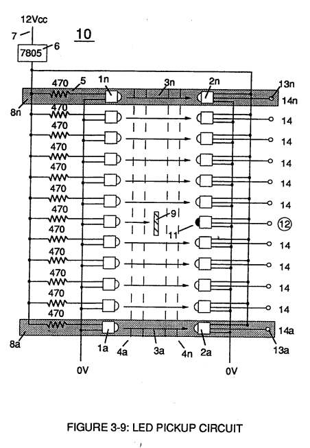
Led Pickup Circuit (10) of Figure (3-9) · Laser Accelerator Assembly
-
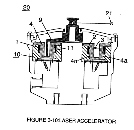
Light-gate (9) integrated with led pickup circuit (10) make up Laser Accelerator assembly (20), as shown in Figure (3-10). · Laser Accelerator Assembly
-
Laser Accelerator (20) of Figure (3-10) · Laser Distributor
-
The figure it sits on · WFC 422DA - Illustrations
-
The figure it sits on · WFC 422DA - Illustrations
-
The figure it sits on · Voltage Intensifier Coil Assembly
Where it is named · 10
Laser Accelerator Assembly 6×
-
Optical lens (4)
Optical lens (4) of Figure (310) redirects and focuses the transmitted light source (3) of Figure (3-9) (traveling infrared light waves) to the Optoschmitt (2) by passing the light source through a series of concentric lenses (4a xxx 4n) of Figure (3-10) which become progressively smaller from the outer peripheral lens surface (4a) to the inner lens surface (4n).
-
concentric lenses (4a xxx 4n)
Optical lens (4) of Figure (310) redirects and focuses the transmitted light source (3) of Figure (3-9) (traveling infrared light waves) to the Optoschmitt (2) by passing the light source through a series of concentric lenses (4a xxx 4n) of Figure (3-10) which become progressively smaller from the outer peripheral lens surface (4a) to the inner lens surface (4n).
-
outer peripheral lens surface (4a)
Optical lens (4) of Figure (310) redirects and focuses the transmitted light source (3) of Figure (3-9) (traveling infrared light waves) to the Optoschmitt (2) by passing the light source through a series of concentric lenses (4a xxx 4n) of Figure (3-10) which become progressively smaller from the outer peripheral lens surface (4a) to the inner lens surface (4n).
-
inner lens surface (4n)
Optical lens (4) of Figure (310) redirects and focuses the transmitted light source (3) of Figure (3-9) (traveling infrared light waves) to the Optoschmitt (2) by passing the light source through a series of concentric lenses (4a xxx 4n) of Figure (3-10) which become progressively smaller from the outer peripheral lens surface (4a) to the inner lens surface (4n).
-
spatially concentric lenses (4a xxx 4n)
The spatially concentric lenses (4a xxx 4n) of Figure (3-10) causes the beam angle of the light source to trigger the Optoschmitt (2) beyond the minimum irradiance that is needed to switch the Optoschmitt from quiescent state (high logic state I B+ ) to on-state (output changing to zero volts).
-
optical lens (4)
Together, the matched infrared devices (1)(2) with optical lens (4) forms optical circuit (8) of Figure (3-9).
Energy Pumping Action 3×
-
electrical tension (4)
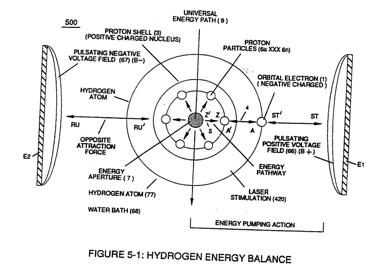
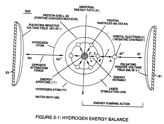
... applying and superimposing electrical tension (4) onto opposite attraction force (AA') that exist between the negative charged orbital electron (1) and positive charged Proton (3)
-
electrical tension (4 / 5)
Interlocked together, the resultant "Electrical Tension of Forces" (4/5) is directly related to Voltage Intensity (ST - ST' / RU - RU' ) of applied voltage fields (66/67) which is variable as to applied voltage amplitude ( Vo xxx ). Increasing voltage amplitude ( xxx Vn) still further increases electrical tension (4 / 5 ) being applied to Energy Aperture (7) or vice versa.
-
Electrical Pressure (4 / 5)
This established increase or decrease in Electrical Pressure (4 / 5 ), now causes Energy Aperture (7) to either enlarge or become smaller as to applied voltage amplitude (VO xxx Vn), respectively.
A Technique Called "Easer" 1×
-
atomic electrical attraction force (4)
... whereby, atomic electrical attraction force (4) that exists between the deflected orbital negative charged electron -(1) and the pivotal positive charged Proton (3) is attenuated (∆4a xxx ∆4n - ∆5a xxx ∆5n)