(17) · also written as a run, 17a xxx 17n
Pulse width
Also written variable unipolar pulse · Laser Injection · stop-position
Where it is first named
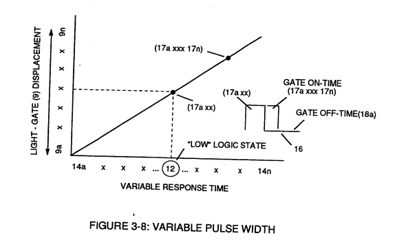
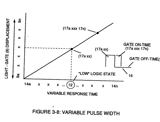
Circuit (30) electronically and automatically scans output signal-array (14axxx ... 12 ... xx14n) (15) until circuit (30) locates, momentarily registers, and translates response-time (14a xxx ... 12) into a variable unipolar pulse (17/18) of Figure (3-8).
How it is written
- (17) 10×
- (17/18) 1× with (18) Variable Unipolar Pulse
- (17a) 1×
- (17a xxx) 1×
- (17a xxx 17n) 1×
- (17a xxxx 17n) 1×
17a xxx 17n is Meyer's shorthand for a run of the same thing: 17a is the first, 17n the last, and the x's stand for however many lie between. Every stage of the run is this one numeral.
Drawings 51
-
Stanley A. Meyer Page_3 of 28 · WFC 417 — WFC 417
-
Stanley A. Meyer Page17 of 28 · WFC 417 — WFC 417
-
Stanley A. Meyer Page27 of 28 · WFC 417 — WFC 417
-
Stanley A. Meyer Page 28 of 28° · WFC 417 — WFC 417
-
Carries this number · Figure 9B & 9BB - Applied Voltage To Plates
-
Figure (1-3) · LC Circuit
-
Figure (1-5) · LC Voltage
-
Le is light intensity in watt; T1 is current on-time; T2 is current off-time; and (ION)=RMS value of load current during on-period. · Laser Interaction
-
Resonant Cavity Assembly, as illustrated in Figure (1-17) · Electron Extraction Process
-
Carries this number · Acceleration Control Circuit (30)
-
Toggling action at full-scale deflection (13a xxx 13n) occurs in the range of (10) kHz or above and thus, allows instant response to driver's acceleration demands. · Acceleration Control Circuit (30)
-
Figure (3-13) · Acceleration Control Circuit (30)
-
Figure (3-13) · Acceleration Control Circuit (30)
-
Carries this number · Analog Voltage generator (40)
-
Figure (3-15) · Voltage Amplitude Control Circuit (50)
-
Carries this number · Gated Pulse Frequency generator (80)
-
In terms of assembly, gas resonant cavity (410), electron extraction circuit (270), optical lens (121) forms gas processor (260) of Figure (3-31). · Gas Processor
-
Carries this number · WFC 422DA - Illustrations
-
Carries this number · WFC 422DA - Illustrations
-
Carries this number · WFC 422DA - Illustrations
-
Carries this number · WFC 422DA - Illustrations
-
Carries this number · WFC 422DA - Illustrations
-
Carries this number · Electronic Circuit Design
-
Carries this number · Electronic Circuit Design
-
Carries this number · Electronic Circuit Design
-
Carries this number · Electronic Circuit Design
-
Carries this number · Differential Air-Gas Inlet Control
-
Water Fuel Injection System (10) of Figure (1) · Water Fuel Injector (Taper Resonant Cavity Chamber)
-
Carries this number · Water Fuel Injector (Taper Resonant Cavity Chamber)
-
Figure (17) · Water Fuel Injector (Taper Resonant Cavity Chamber)
-
Carries this number · Funneling Effect
-
(520) of Figure (4-3) · Funneling Effect
-
thereby, attenuating voltage amplitude (voltage intensity) beyond Secondary Coil (53) voltage levels (71), as illustrated in (220) of Figure (18). · Funneling Effect
-
Carries this number · Funneling Effect
-
Figure 1-3 · Amp Inhibiting Circuit Vs Voltage Enhancement
-
Ambient Air Ionizer (Gas Processor) (80) of Figure (4-6) · Water Fuel Injection System - Page 3
-
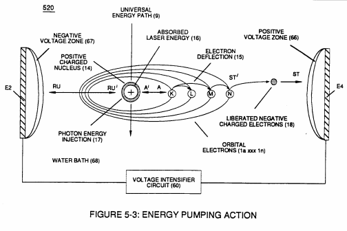
Carries this number · Energy Pumping Action
-
(520) in Figure (5-3) · Resonant Propagation
-
(520) of Figure (5-3) · In Application of Usage
-
(520) of Figure (5-3) · Solar Energy Actuator
-
Carries this number · Illustrations
-
Hydrogen Fracturing Process (520) of Figure (5-3) · Voltage Intensifier Coil-Assembly
-
(520) of Figure (5-3) · 8-2 - Traveling Voltage Wave-Guides
-
WFC Gas Processor (80) of Figure (1-17) · WFC Development Objectives
-
Energy Pumping Action (520) of Figure (5-3) · WFC Development Objectives
-
When (B+/B+ - B-/B- / 1030B) switch function is activated, switch terminals (T1/T2 - T3/T4) are closed. · Electrical Crossover Switching Circuit
-
3-8 Multi-Coil Spool · Voltage Intensifier Coil Assembly
-
3-13 Flat Seal · Voltage Intensifier Coil Assembly
-
Figure (5-4C) · Resonant Propagation
-
The figure it sits on · Illustrations
-
5-4 C · 8-4 - State Space (Sp)
Where it is named · 15
Acceleration Control Circuit (30) 3×
-
variable unipolar pulse (17/18)
Circuit (30) electronically and automatically scans output signal-array (14axxx ... 12 ... xx14n) (15) until circuit (30) locates, momentarily registers, and translates response-time (14a xxx ... 12) into a variable unipolar pulse (17/18) of Figure (3-8).
-
Pulse width (17a xxx 17n)
Pulse width (17a xxx 17n) diminishes when logic-point (12) reverses direction to start .. position (9a).
-
pulse width (17a xxx)
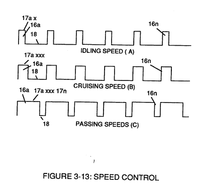
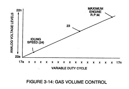
In retrospect to engine performance (gas pedal attenuation) (21) of Figure (3-10), a wider pulse width (17a xxx) of Figure (3-13C) increases (accelerates) engine R.P.M.; whereas, smaller pulse-width (17ax) reduces (de-accelerates) engine R.P.M .. Cruising speed (3-13B) of Figure (3-13) is simply accomplished when pulse width remains constant.
Analog Voltage generator (40) 2×
-
stop-position (17a xxxx 17n)
Widening pulse width to stop-position (17a xxxx 17n) of Figure (3-13) causes analog signal (22) to increase to higher voltages levels; whereas, analog voltage level (22) drops (become lower in value) in voltage level when pulse width decreases to start-position (17a).
-
Widening pulse width to stop-position (17a xxxx 17n) of Figure (3-13) causes analog signal (22) to increase to higher voltages levels; whereas, analog voltage level (22) drops (become lower in value) in voltage level when pulse width decreases to start-position (17a).
Water Fuel Injector (Taper Resonant Cavity Chamber) 7×
-
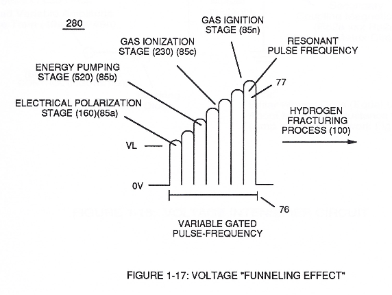
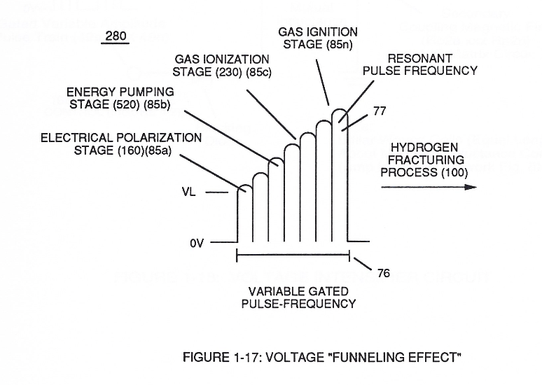
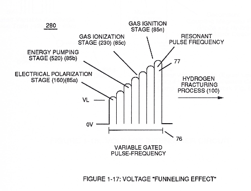
Once water fuel-droplets (xxx 48n) fully occupies open space cavity (Resonant Cavity Zone) (35) and then exposed to applied pulsating opposite electrical voltage fields (49/51) of voltage wave form (280) of Figure (17), the electrically stimulated water fuel droplets (48a xxx 48n) are subjected to release thermal explosive energy (gtnt) (16) undergoing Electrical-Resonant in a sequential manner:
-
and finally, spark-ignite the highly destabilized combustible gases (laser primed combustible gases having missing electrons) by electrostatic discharge (kinetic energy agitation), as further exemplified in (280) of Figure (17);
-
Subsequent and repetitive formation of applied gated electrical voltage pulse-train (210a xxx 210n) of Figure (17) to continued in-flow of water fuel droplets (48a xxx 48n) not only sustains and maintains Hydrogen Fracturing Process (100) of Figure (6) but, also, regulates Thermal Explosive Energy release (16a x …
-
Voltage Intensifier Circuit (220) of Figure (18) allows Electrical-Stress variation (SS' = RR' / TT' = UU') since voltage Intensifier Circuit (220) inhibits electron-flow (amp restriction) into voltage triggering process (210) of Figure (17) as to (100) of Figure (6).
-
voltage triggering process (210) of Figure (17)
-
Adjusting Pulse-train (210a xxx 210n) in such a way as to allow pulse off-time (T2) to be synchronized with collapsing and re-formation of electromagnetic field coupling across pulsing transformer (52/53) to produce unipolar pulse frequency (T1a xxx T1n), as illustrated in (220) of Figure (18) as to Figure (17).
-
Figure (17)
Funneling Effect 2×
-
This resultant "Funneling Effect" (260), now, allows voltage amplitude (Vn) wave-form (58) to travel the length of Resonant Cavity Zone (35) from Start-Point (85a) to End-Point (85n) increasing voltage intensity (xxx VL = Vn) as parallel voltage surfaces (83/84) diminishes in size relationship (85a ~ 85n), as illustrated in (210) of Figure (17).
-
Attenuating variable voltage amplitude (72a xxx 72n) in conjunction with incoming gated pulse-train (210a xxx 210n), now, expands gated pulse width (76a xxx 76n) as voltage amplitudes (Vo xxx Vn) increases, forming step up voltage wave Form (77) of Figure (17).
Resonant Propagation 1×
-
Laser Injection (17)
Resonant Action (21), Compounding Action (22), Laser Injection (17). and Energy Pumping Action (520), Now, allows the production of hydrogen and oxygen gases from water in geometrical progression to set up Hydrogen Fracturing Process (90). as illustrated in Figure (5-4C) as to Figure (5-5).