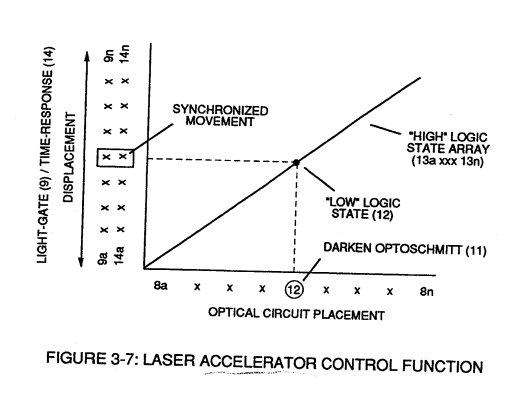
Figure (3-7)
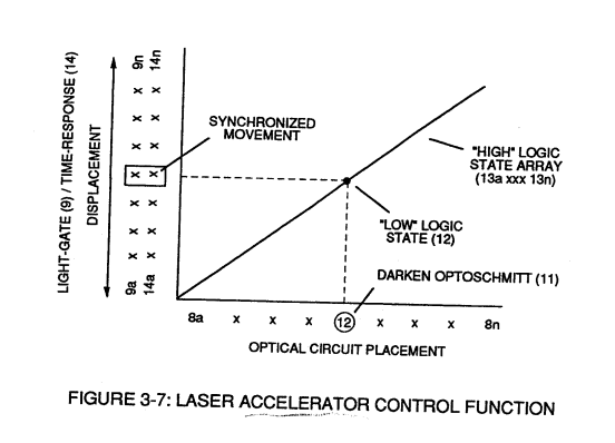
Laser Accelerator Control Function
Also written VIC Amp Inhibitor Coil Ass
How it is written
- (3-7) 7×
Drawings 4
-
Captioned as this figure · Laser Accelerator Assembly
-
Figure (3-7) · Acceleration Control Circuit (30)
-
Captioned as this figure · WFC 422DA - Illustrations
-
3-7 VIC Amp Inhibitor Coil Ass'y · Voltage Intensifier Coil Assembly
On this figure 4
Where it is named · 7
Laser Accelerator Assembly 2×
-
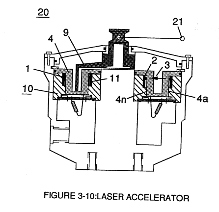
To perform a switch-logic function, light - gate (9) of Figure (3-9) as to Figure (3-10) is inserted between the matched infrared devices (1)(2) and moved in a linear displacement from one optical circuit (8x) to another optical circuit (8xx), as illustrated in Figure (3-9)(3-10) as to Figure (3-7).
-
Reversing the direction of the light-gate (9) once again reinstates the original sequential switching order, as illustrated in Figure (3-7) and Figure (3-9).
Acceleration Control Circuit (30) 5×
-
Moving light-gate (9) of figure (3-9) in direct relationship to the physical placement of optical circuits (8a xxx 8n), sets up a time variable (14a xxx 14n) of Figure (3-7) from optical circuits (8x) to another optical circuit (8xx) and/ or (8xxx) or to (8n) since the triggered low logic state (12) of Figure (3-7) and (3-8) moves in direct relationship to the displaced …
-
… xxx 8n), sets up a time variable (14a xxx 14n) of Figure (3-7) from optical circuits (8x) to another optical circuit (8xx) and/ or (8xxx) or to (8n) since the triggered low logic state (12) of Figure (3-7) and (3-8) moves in direct relationship to the displaced light-gate (9), as illustrated in Figure (3-12).
-
Figure (3-7)
-
… xxI4n) or signal output (15) of Figure (3-5) is, now, electrically transmitted to Acceleration Control Circuit (30) of Figure (3-5) since Laser Accelerator Assembly (20) of figure (3-10) converts mechanical displacement (9a xxx 9n) to electrical time-response (14a xxx 14n) of Figure (3-7) by linearly moving (forward and/or reverse direction) "low" logic state signal (12) in a array of "high" logic state output signals (13a xxx 13n), as further illustrated in Figure (3-8) and Figure (3 …
-
Figure (3-7)