(63)
Resonant frequency
Also written electromagnetic field · pulse frequency · pulse-frequency
Where it is first named
Variable pulse frequency generator (70) of Figure (3-5) varies and adjusts pulse frequency (63) (50% duty cycle pulse) while gated pulse frequency generator (80) of Figure (3-5) varies and adjusts pulse width (54a xxx 54n).
How it is written
- (63) 4×
- (63/64) 1× with (64) Pulse Train
Drawings 18
-
where Resonant frequency (63) of LC circuit in series is given by (Eq 4) · Voltage Intensifier Circuit (60)
-
Carries this number · Steam Resonator Assembly
-
Figure (3-24) · Inductance (FL)
-
Figure (3-5) · Acceleration Control Circuit (30)
-
Analog Voltage Circuit (40), as shown in Figure (3-5) · Acceleration Control Circuit (30)
-
Figure (3-5) · Acceleration Control Circuit (30)
-
Figure (3-5) · Analog Voltage generator (40)
-
Figure (3-19) · Cell Driver Circuit (90)
-
Figure (3-19) · Voltage Intensifier Circuit (60)
-
Figure (3-28) · Voltage Intensifier Circuit (60)
-
Ohm's law of LC circuit (180) of Figure (3-28) in series is given by (Eq 5) · Voltage Intensifier Circuit (60)
-
Voltage (Vc) of Figure (3-28) across the capacitor is given by (Eq 7) · Voltage Intensifier Circuit (60)
-
Figure (3-5) · Laser Distributor
-
The figure it sits on · WFC 422DA - Illustrations
-
The figure it sits on · WFC 422DA - Illustrations
-
The figure it sits on · WFC 422DA - Illustrations
-
3-5 Outer Core Bobbin · Voltage Intensifier Coil Assembly
-
The figure it sits on · 8-1 - Propagating "Resonant Action" By Voltage Tickling of State Space
Where it is named · 5
Voltage Intensifier Circuit (60) 4×
-
pulse frequency (63)
Variable pulse frequency generator (70) of Figure (3-5) varies and adjusts pulse frequency (63) (50% duty cycle pulse) while gated pulse frequency generator (80) of Figure (3-5) varies and adjusts pulse width (54a xxx 54n).
-
Resonant frequency (63)
Resonant frequency (63) of Figure (3-19) can be raised or lowered by changing the inductance (56) and/or capacitance (57) valves.
-
pulse-frequency (63)
The value of inductor (56), value of capacitor (57), and the pulse-frequency (63) of voltage (Yo xxx Vn) being applied across the LC circuit determined the impedance of LC circuit (Figure 3-28).
-
Resonant frequency (63)
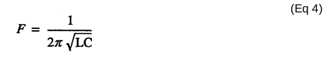
where Resonant frequency (63) of LC circuit in series is given by (Eq 4)
Water Fuel Injector (Taper Resonant Cavity Chamber) 1×
-
electromagnetic field (63/64)
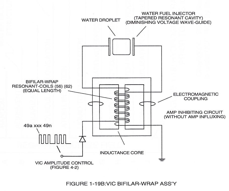
The "Plus Factor" is that induce external electromagnetic field (63/64) across Resonant coil-Tap (67) increases voltage intensity (voltage potential) still further rather than diminishes peak voltage potential due to resistive valve of the stainless steel wire.