patent · US20100181190A1
Hydrogen and oxygen gases, produced on demand by electrolysis, as a partial hybrid fuel source for internal combustion engines
22 July 2010
Page 1 — bibliographic record
(19) United States (12) Patent Application Publication (10) Pub. No.: US 2010/0181190 A1
Romaniuk (43) Pub. Date: Jul. 22, 2010 (54) HYDROGEN AND OXYGEN GASES, (30) Foreign Application Priority Data
PRODUCED ON DEMAND BY
ELECTROLYSIS,ASA PARTIAL HYBRID Jun. 19, 2007 (CA) ...................................... 2597O68 FUEL SOURCE FOR INTERNAL Publication Classification
COMBUSTON ENGINES
oyal Romaniuk, Ville Mont (52) U.S. Cl. ....................... 204/274; 204/275.1; 204/276
Correspondence Address: A process encompassing hydrogen and oxygen gases as a BROOKS KUSHMAN P.C. partial fuel source when utilized together with a fossil-based 1000 TOWN CENTER, TWENTY-SECOND fuel to power conventional internal combustion engines. FLOOR Hydrogen and oxygen gases are produced by electrolysis in SOUTHFIELD, MI 48075 (US) an electrolyser unit(s), on-demand and on-board a vehicle, or in stationary applications, eliminating the need of highly (73) Assignee: HYTRONXTECHNOLOGIES pressurized hydrogen storage tanks When said gases are INC, Mascouche, QC (CA) introduced into the combustion chamber of the engine, via the air intake assembly, they increase the efficiency of the com bustion burn by enriching the air to fuel ratio, resulting in a (21) Appl. No.: 12/665,406 reduction of i. E. fuels required for pit. engine performance, said gases effectively becoming a partial (22) PCT Filed: Mar. 12, 2008 hybrid fuel source. The process includes scalability for all size and types of installations, cold-weather applications and (86). PCT No.: PCTFCAO8/OO456 longer operating capabilities. As an additional benefit, in direct correlation, this process reduces carbon dioxide emis
S371 (c)(1), sions, and, in varying quantities, other greenhouse gas emis
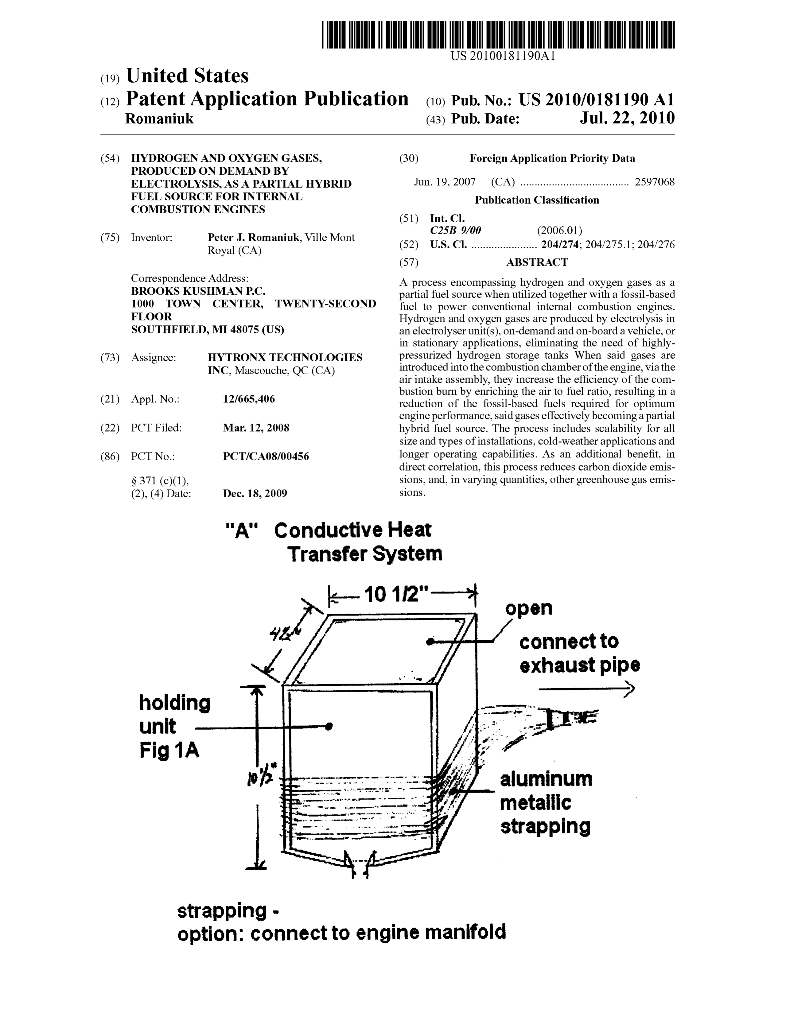
"A" Conductive Heat
Transfer System
Connect to exhaust pipe holding unit
Fig 1A aluminum metallic strapping
strapping - option: connect to engine manifold
Page 2
Drawing sheet — no readable text.
Page 3
Drawing sheet — no readable text.
Page 4
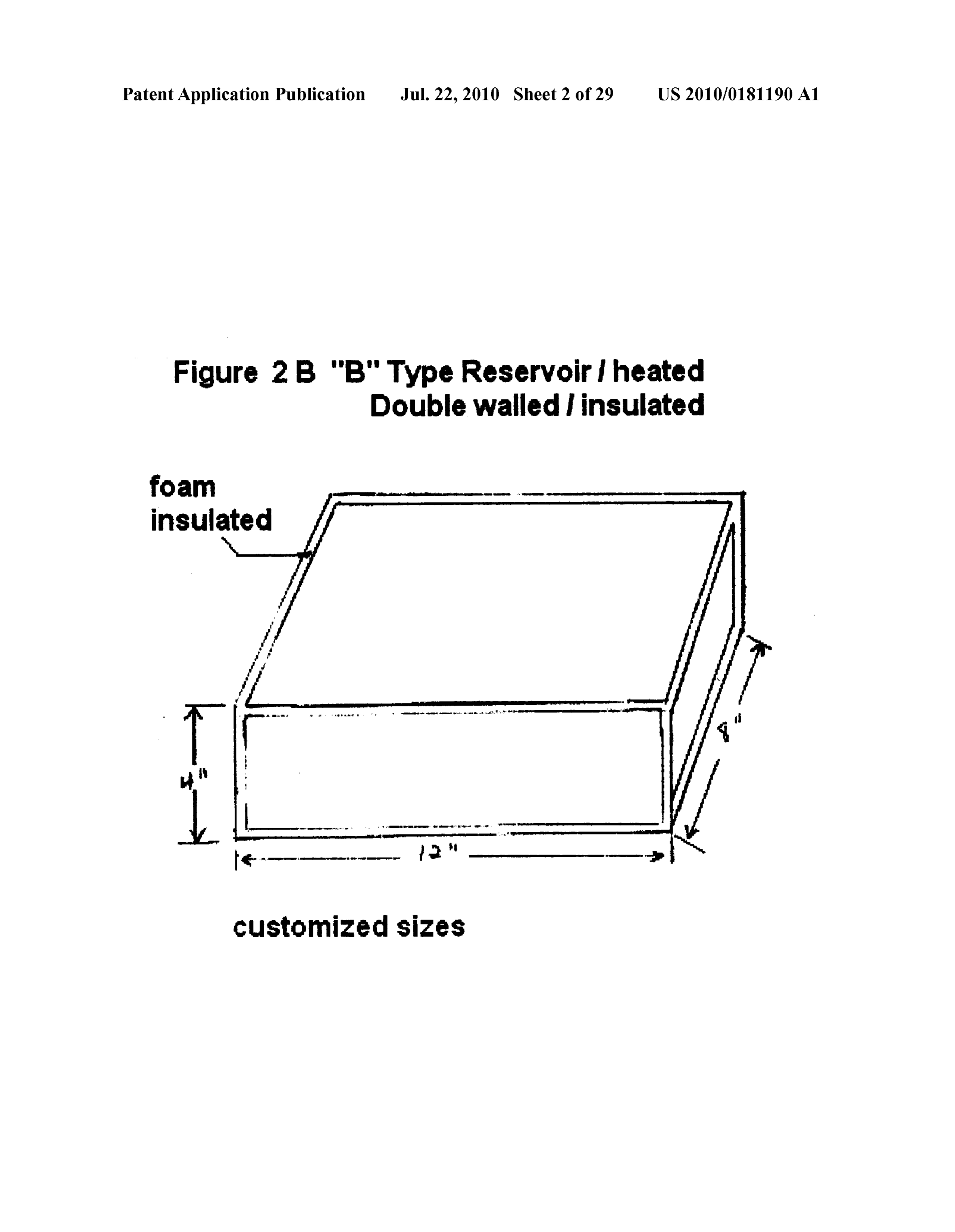
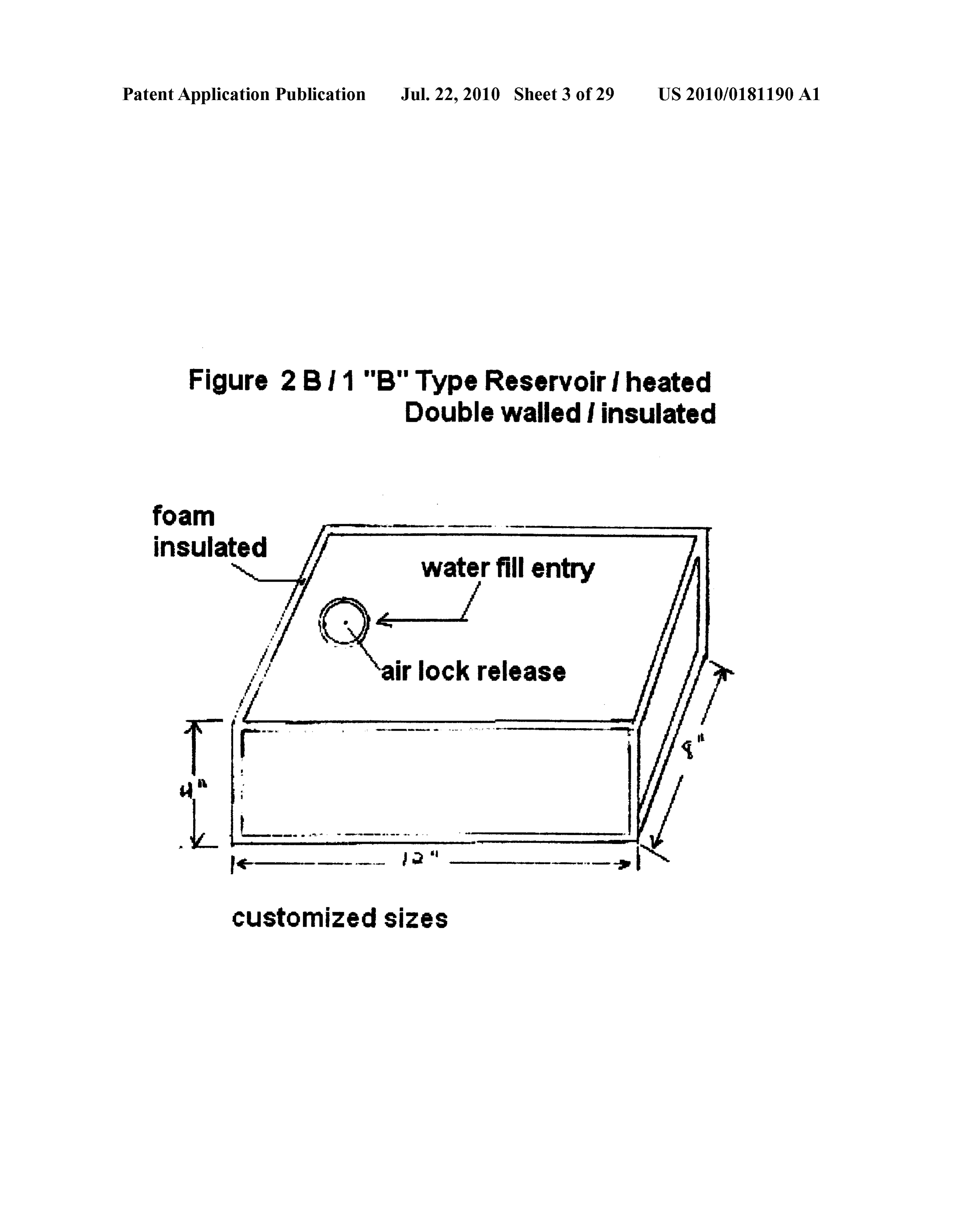
Patent Application Publication Jul. 22, 2010 Sheet 3 of 29 US 2010/O181190 A1 Figure 2 B 1 "B"Type Reservoir I heated Double Walled insulated foam insulated water fill entry
Q air lock release Customized sizes
Page 5
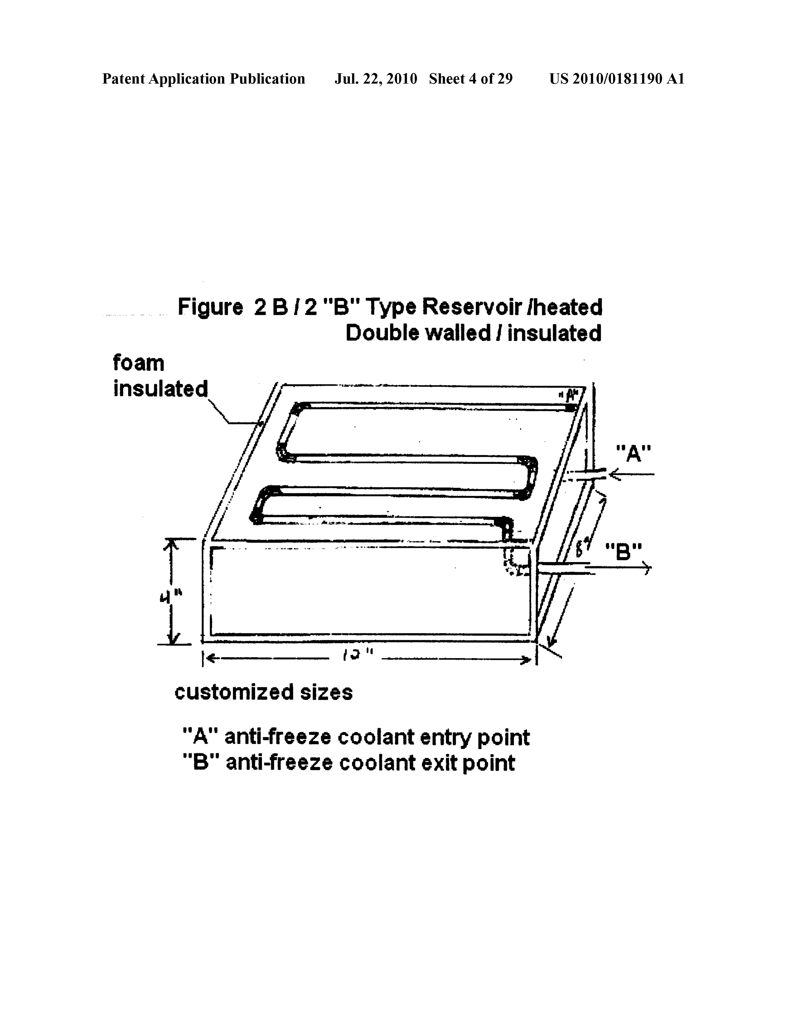
Patent Application Publication Jul. 22, 2010 Sheet 4 of 29 US 2010/0181190 A1 Figure 2 B 12 "B"Type Reservoir heated Double Walled insulated foam
Ice
swas an
Customized sizes
"A" anti-freeze coolant entry point "B" anti-freeze coolant exit point
Page 6
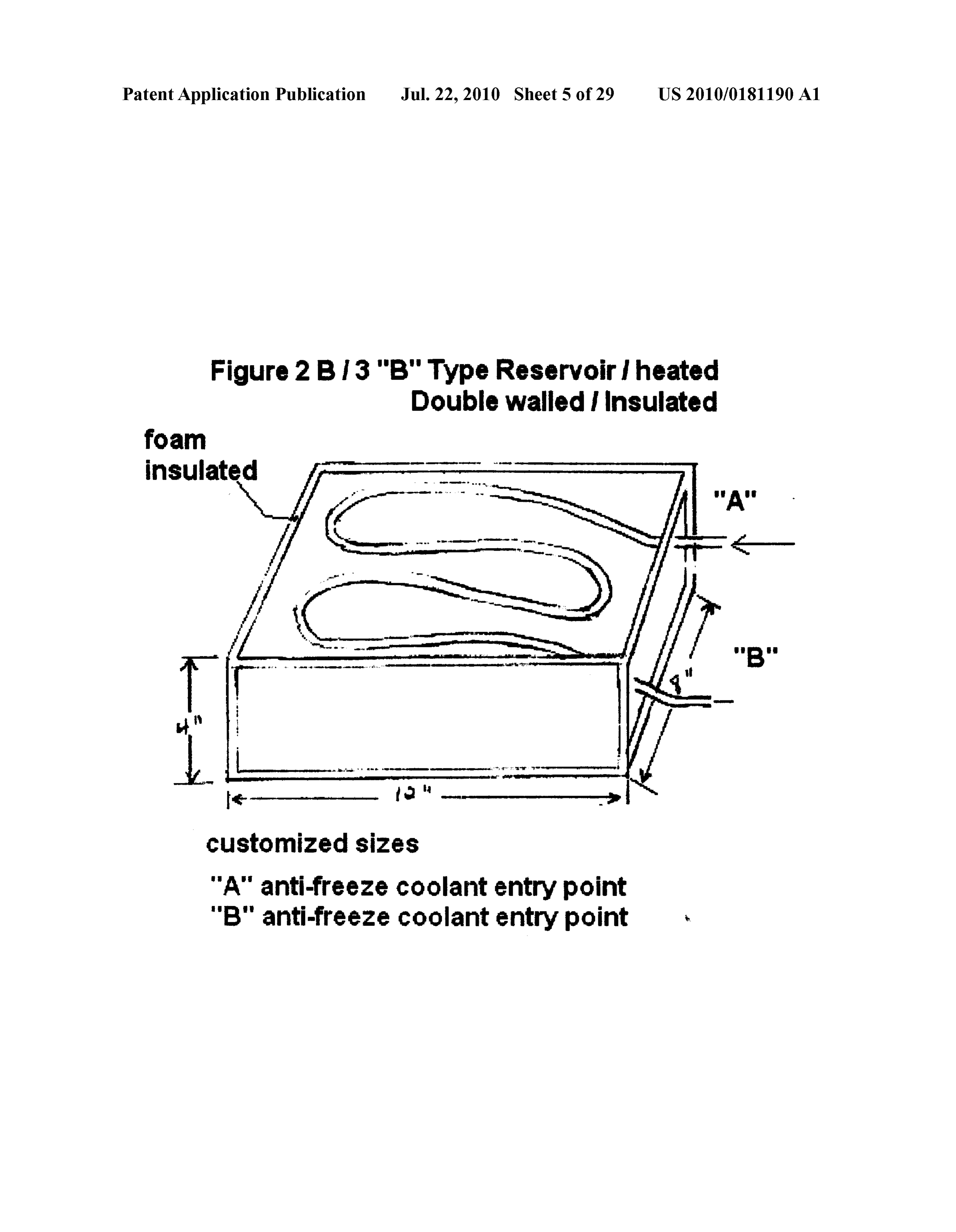
Patent Application Publication Jul. 22, 2010 Sheet 5 of 29 US 2010/O181190 A1 Figure 2 B 13 "B"Type Reservoir heated Double Walled insulated foam insulated customized sizes
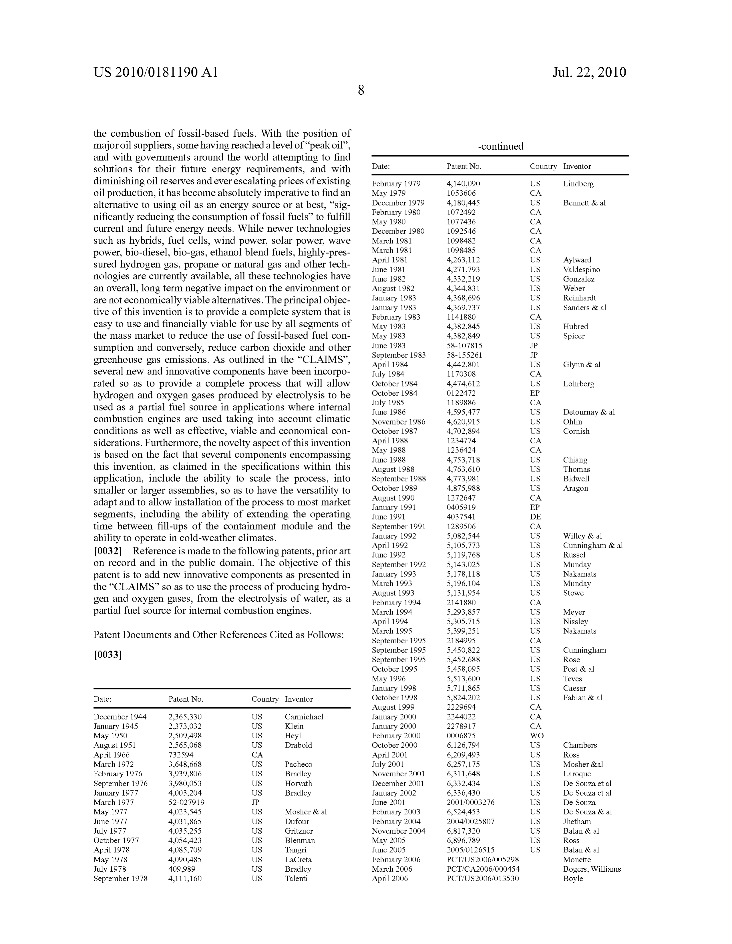
"A" anti-freeze coolant entry point "B" anti-freeze coolant entry point
Page 7
Patent Application Publication Jul. 22, 2010 Sheet 6 of 29 US 2010/0181190 A1
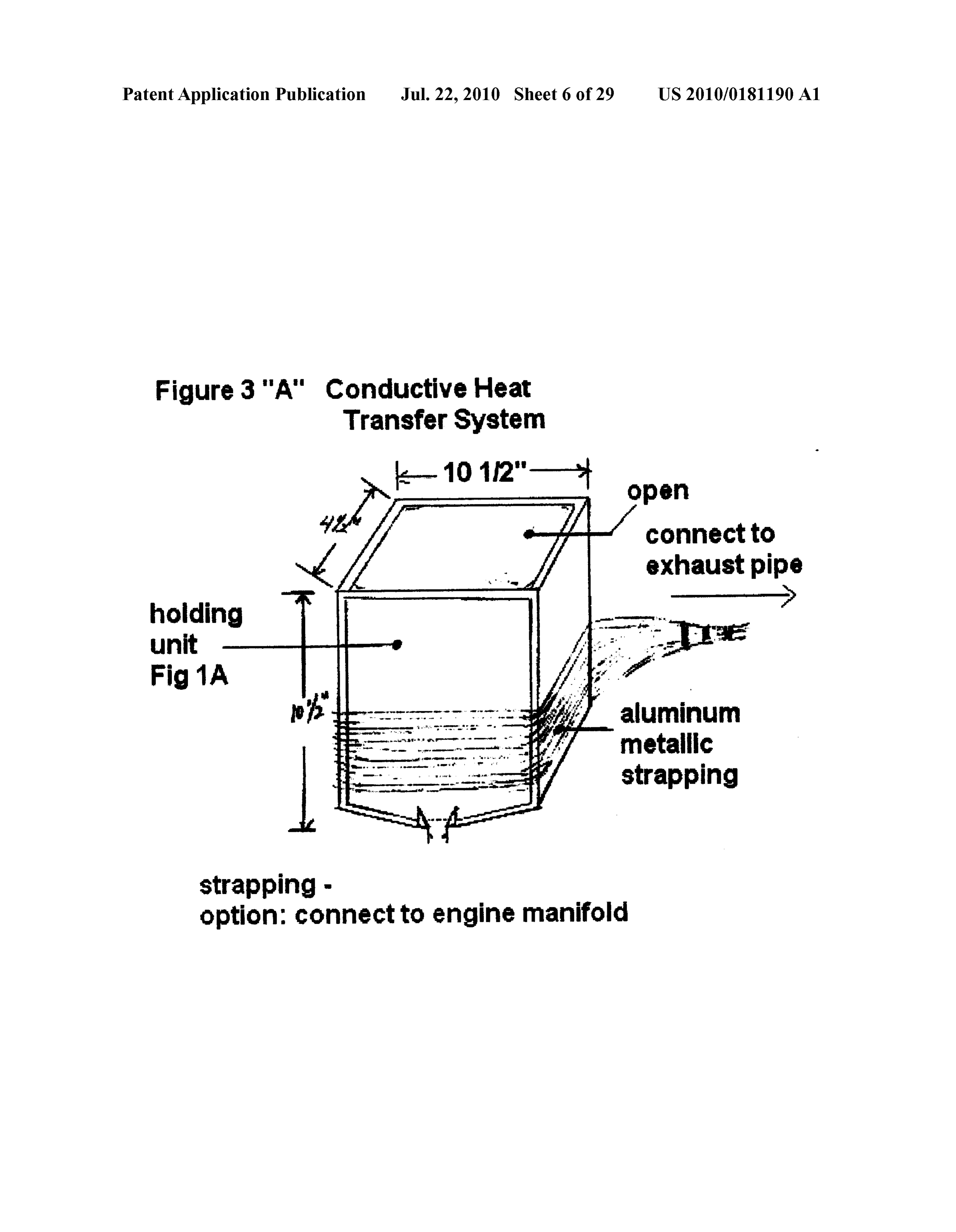
Figure 3 "A" Conductive Heat Transfer System
Connect to exhaust pipe
unit
Fig 1A aluminum metallic strapping
Strapping - option: connect to engine manifold
Page 8
Patent Application Publication Jul. 22, 2010 Sheet 7 of 29 US 2010/O181190 A1
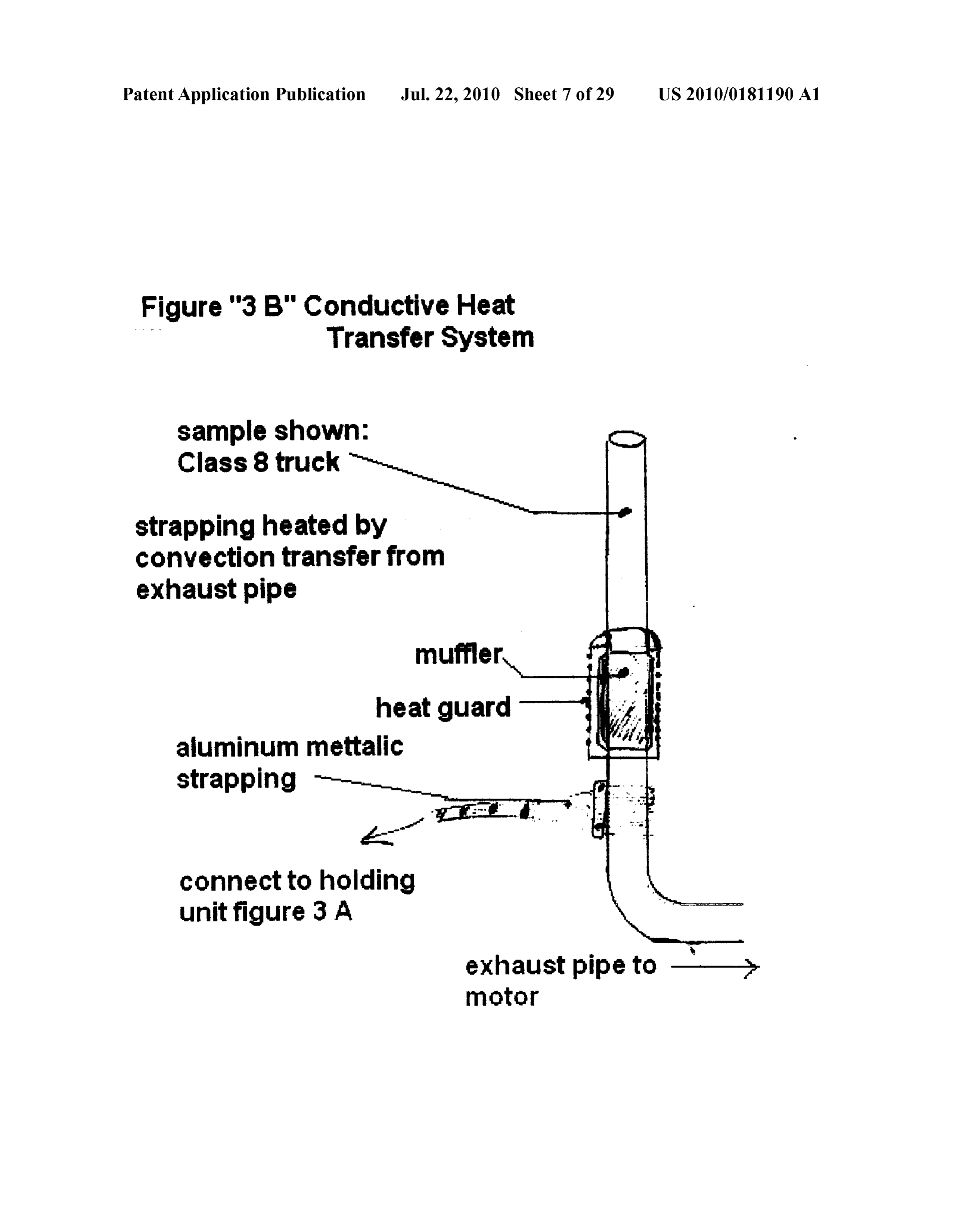
Figure "3 B" Conductive Heat Transfer System
sample shown:
Class 8 truck
strapping heated by convection transfer from exhaust pipe muffler heat guard aluminum metalic strapping
connect to holding unit figure 3 A
motor
Page 9
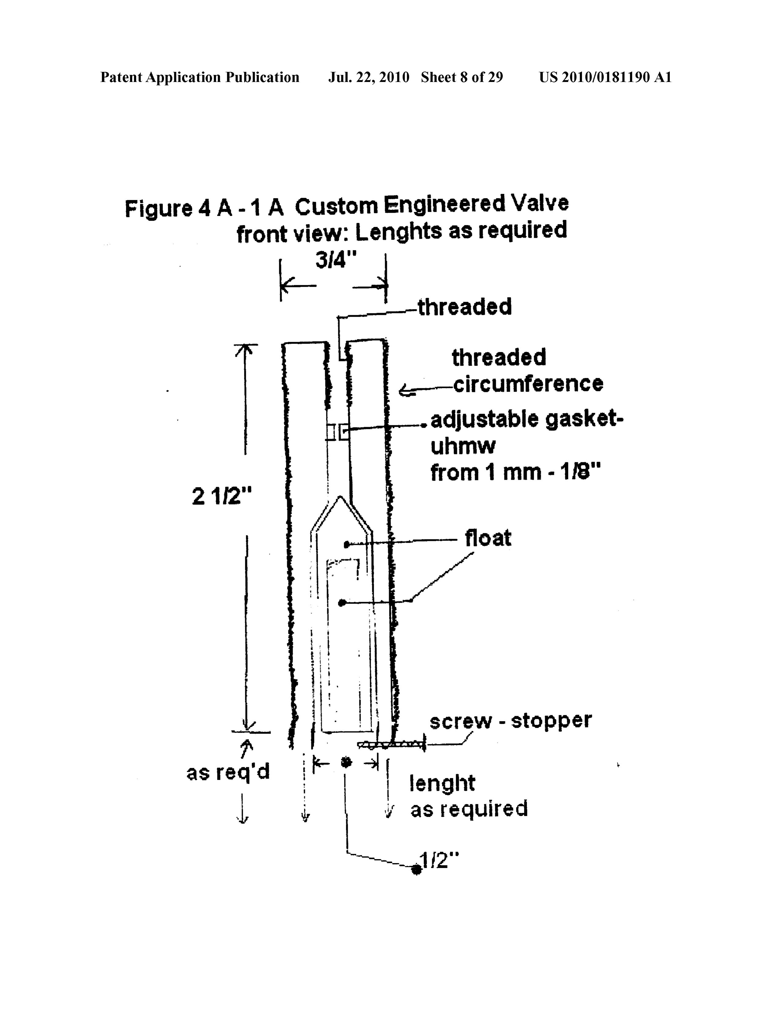
Patent Application Publication Jul. 22, 2010 Sheet 8 of 29 US 2010/O181190 A1 Figure 4 A-1 A Custom Engineered Valve front view: Lenghts as required d threaded
float
ScreW - Stopper
lenght as required
Page 10
Drawing sheet — no readable text.
Page 11
Drawing sheet — no readable text.
Page 12
Drawing sheet — no readable text.
Page 13
Drawing sheet — no readable text.
Page 14
Drawing sheet — no readable text.
Page 15
Drawing sheet — no readable text.
Page 16
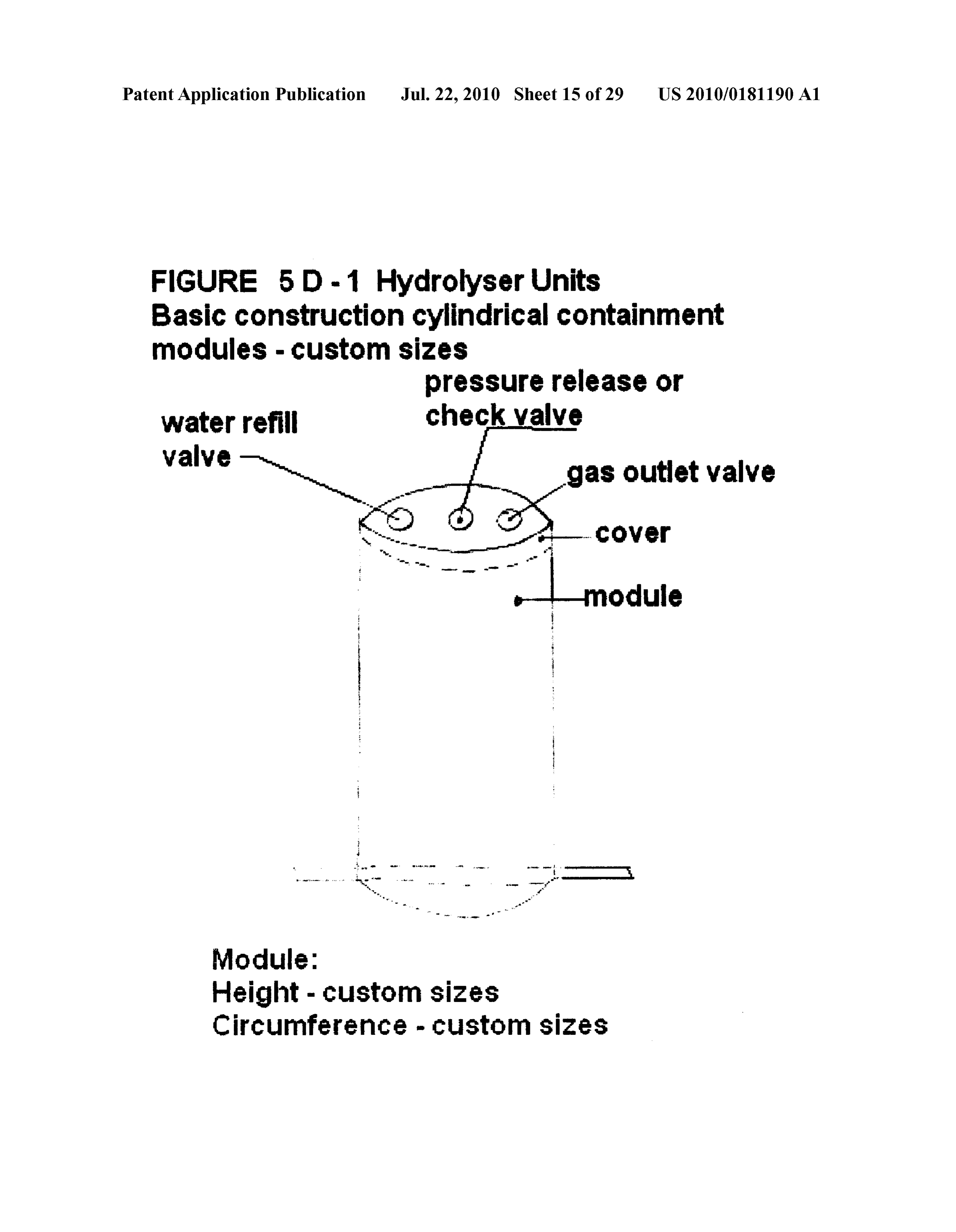
Patent Application Publication Jul. 22, 2010 Sheet 15 of 29 US 2010/O181190 A1 FIGURE 5D-1 Hydrolyser Units
Basic construction cylindrical containment modules - Custom sizes pressure release or
Valve N gas outlet valve
Module:
Height - custom sizes
Circumference - custom sizes
Page 17
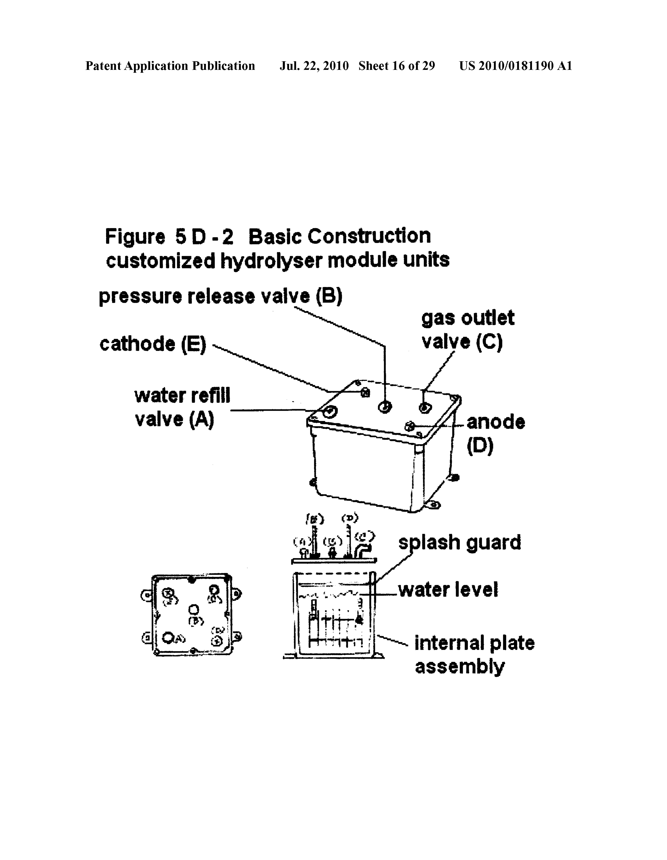
Patent Application Publication Jul. 22, 2010 Sheet 16 of 29 US 2010/O181190 A1 Figure 5 D-2 Basic Construction customized hydrolyser module units pressure release valve (B) gas outlet cathode (E) valye (C) Water refill valve (A) anode Water level
Hit - internal plate assembly
Page 18
Drawing sheet — no readable text.
Page 19
Patent Application Publication Jul. 22, 2010 Sheet 18 of 29 US 2010/O181190 A1
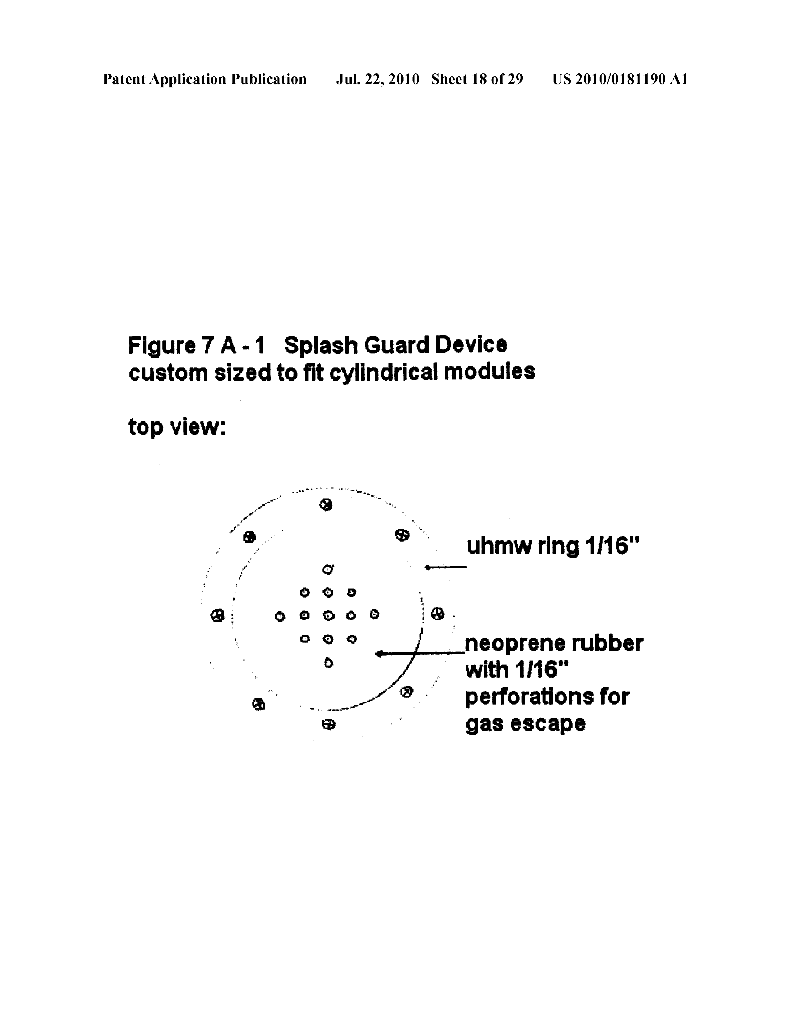
Figure 7 A-1 Splash Guard Device custom sized to fit cylindrical modules top view:
uhmwring 1/16"
1 perforations for gas escape
Page 20
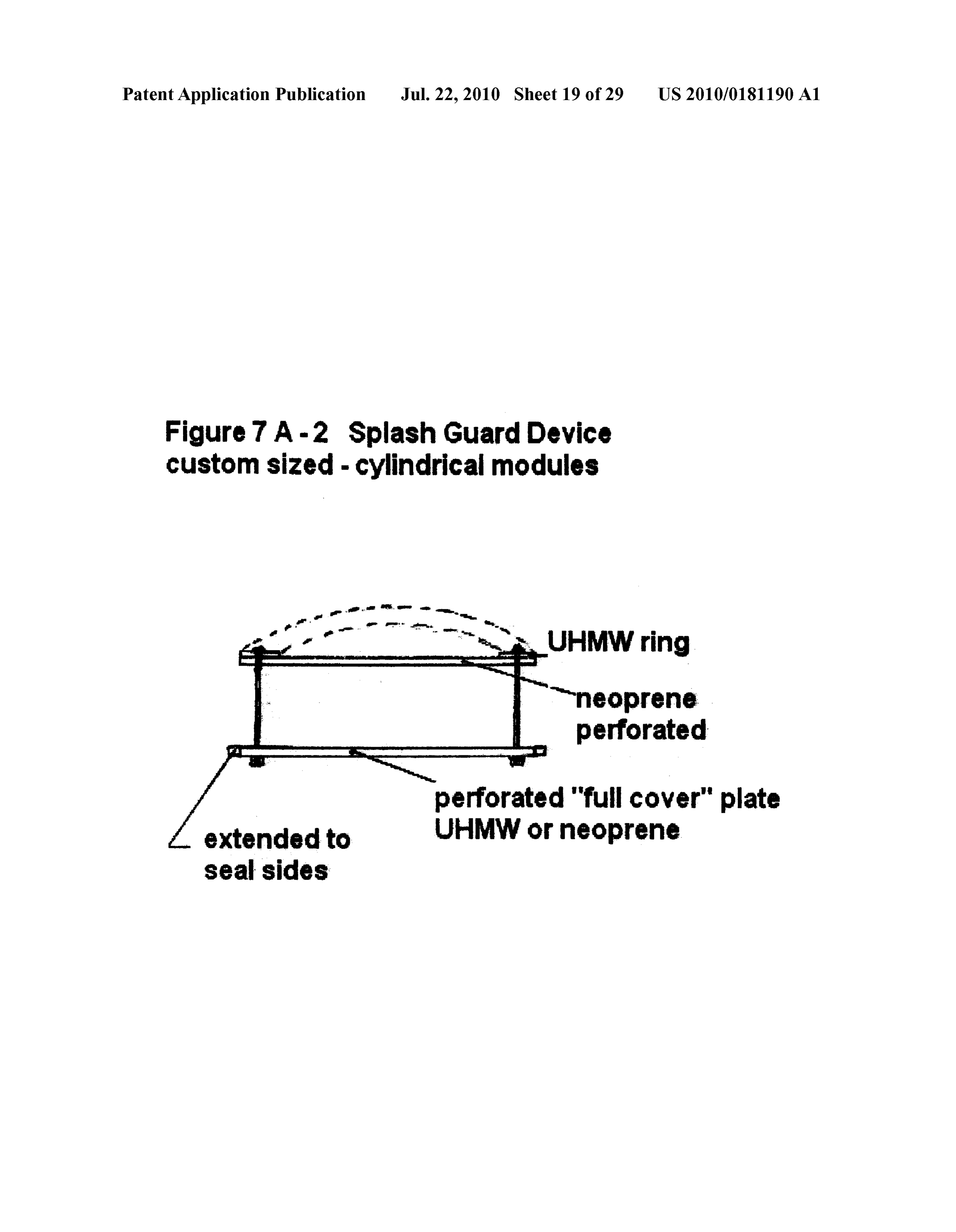
Patent Application Publication Jul. 22, 2010 Sheet 19 of 29 US 2010/O181190 A1 Figure 7 A-2 Splash Guard Device Custom sized- cylindrical modules neoprene perforated perforated "full cover" plate extended to UHMW or neoprene Seal sides
Page 21
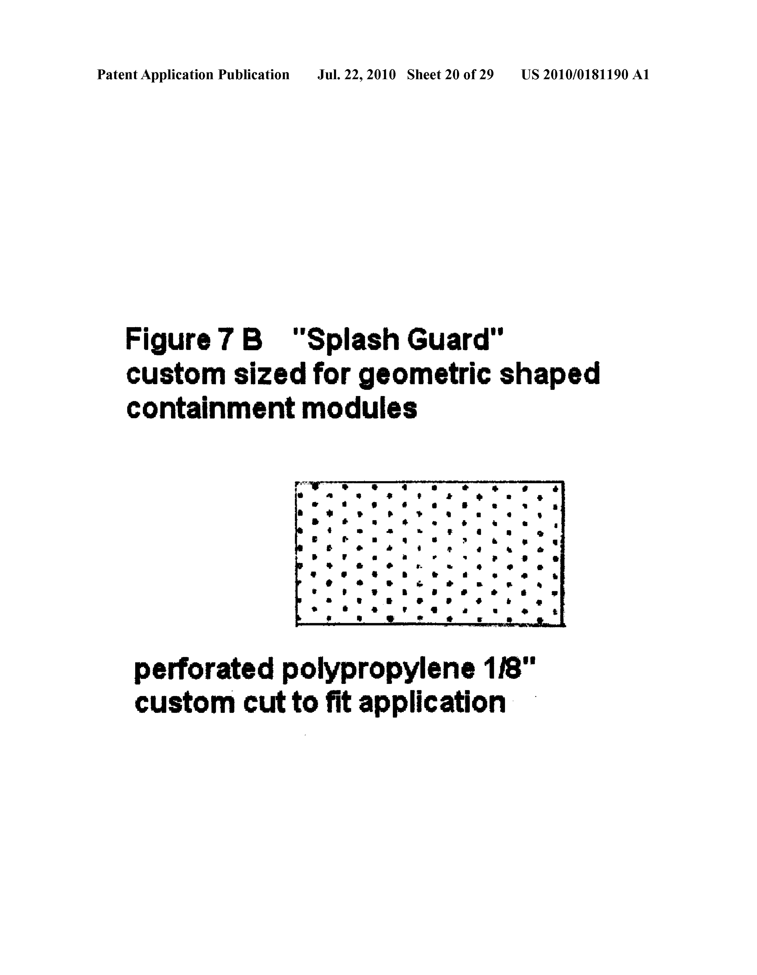
Patent Application Publication Jul. 22, 2010 Sheet 20 of 29 US 2010/O181190 A1 Figure 7B "Splash Guard"
Custom sized for geometric shaped Containment modules firr
perforated polypropylene 1/8" custom cut to fit application
Page 22
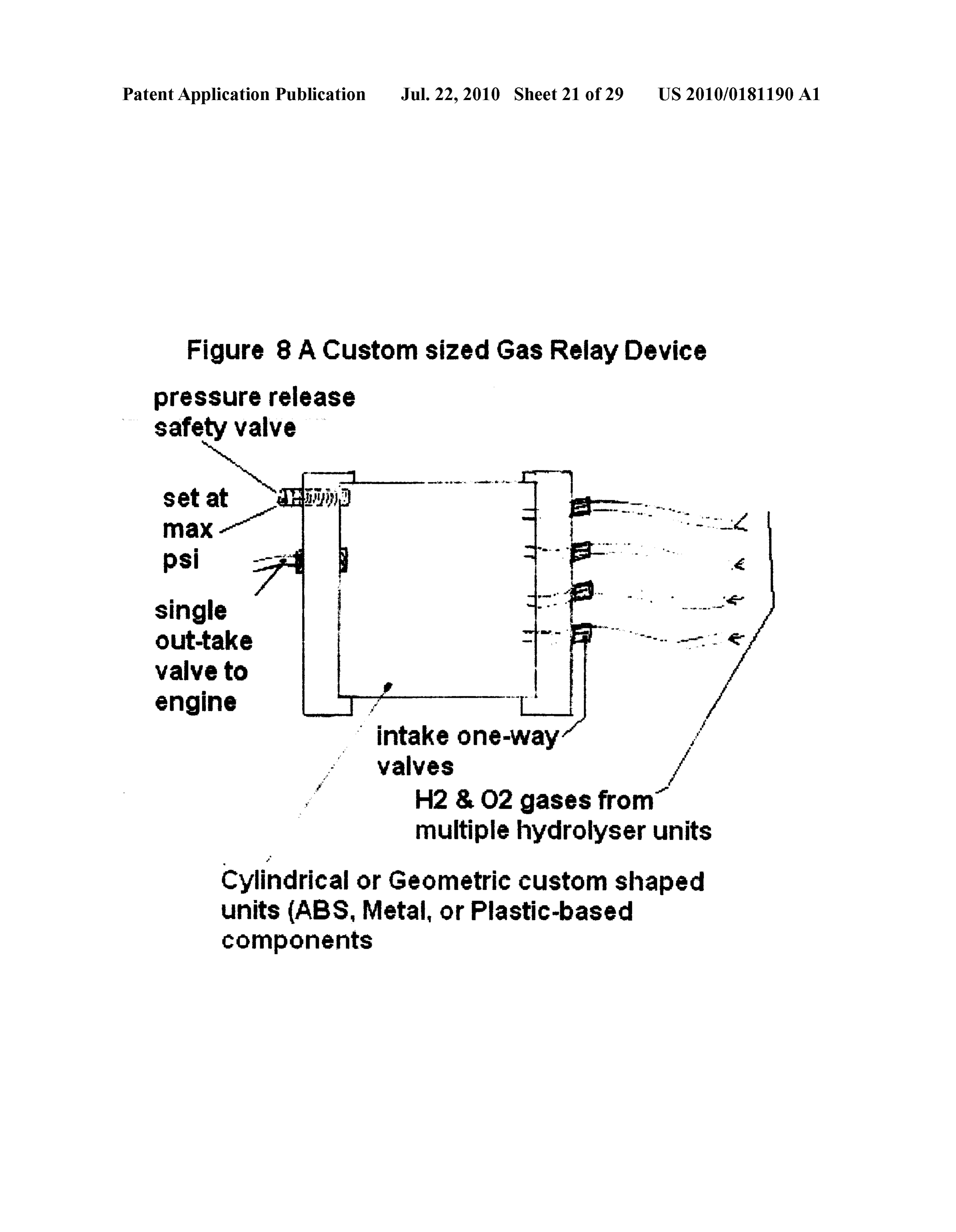
Patent Application Publication Jul. 22, 2010 Sheet 21 of 29 US 2010/O181190 A1
Figure 8A Custom sized Gas Relay Device pressure release
Safety valve
Single
valve to engine intake one-way
H28 O2 gases from multiple hydrolyser units
Cylindrical or Geometric custom shaped units (ABS, Metal, or Plastic-based components
Page 23
Drawing sheet — no readable text.
Page 24
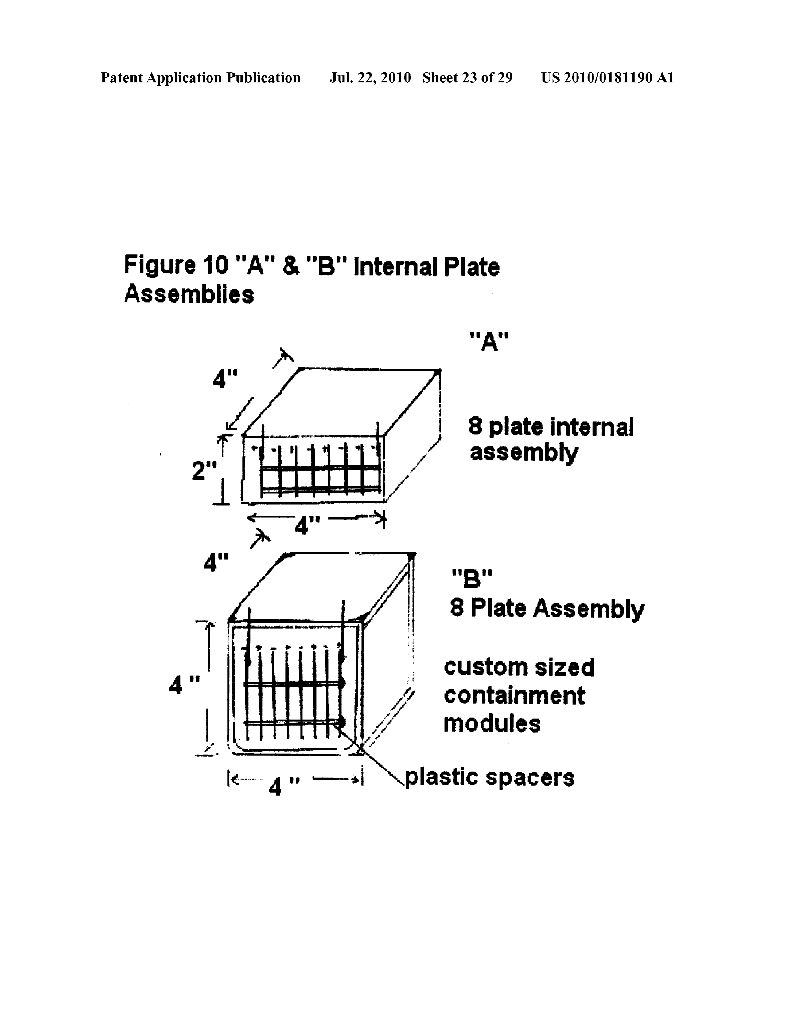
Patent Application Publication Jul. 22, 2010 Sheet 23 of 29 US 2010/O181190 A1 Figure 10 "A" & "B" internal Plate Assemblies
8 plate internal assembly
8Plate Assembly Custom sized containment modules plastic Spacers
Page 25
Drawing sheet — no readable text.
Page 26
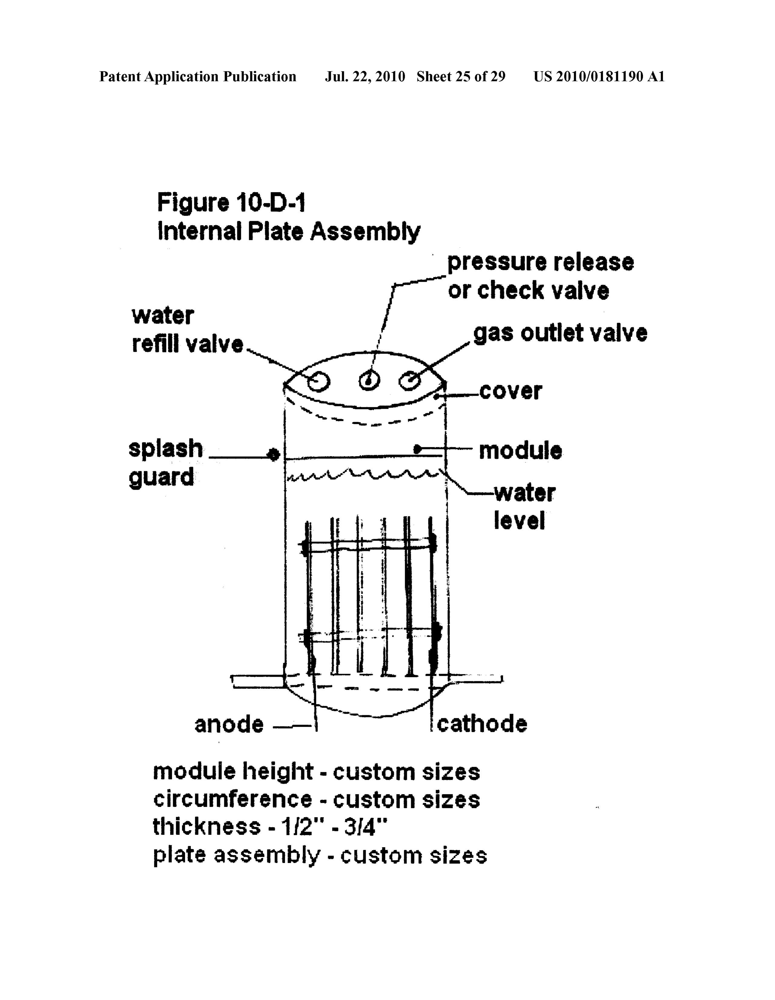
Patent Application Publication Jul. 22, 2010 Sheet 25 of 29 US 2010/O181190 A1 Figure 10-D-1 internal Plate Assembly pressure release
Water |- or check Valve refill valve gas outlet valve
module height - custom sizes circumference - custom sizes
plate assembly - custom sizes
Page 27
Drawing sheet — no readable text.
Page 28
Drawing sheet — no readable text.
Page 29
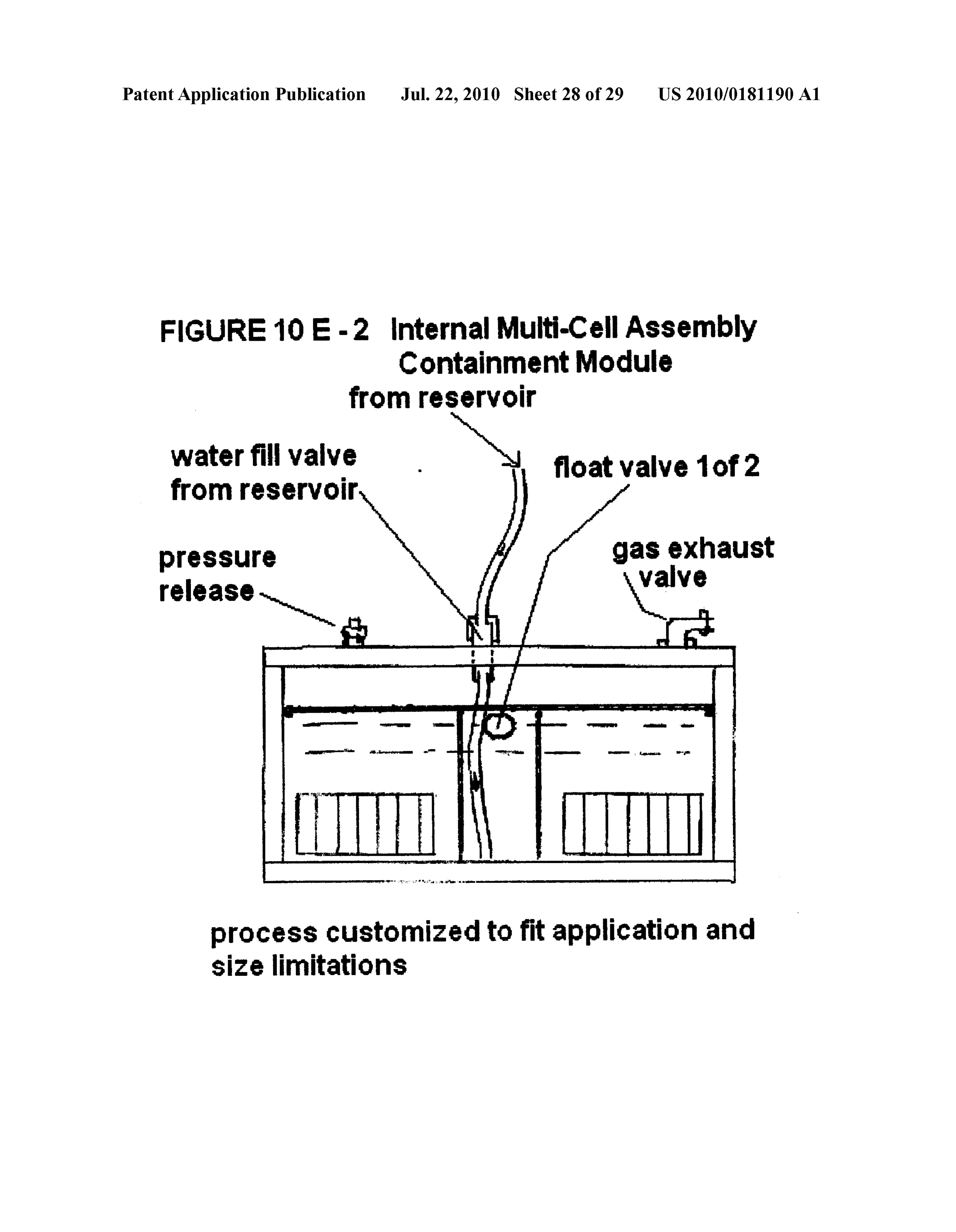
Patent Application Publication Jul. 22, 2010 Sheet 28 of 29 US 2010/O181190 A1 FIGURE 10 E-2 internal Multi-Cell ASSembly Containment Module from reservoir water fill valve N float valve 1 of 2 from reservoir
release
process customized to fit application and size limitations
Page 30
Drawing sheet — no readable text.
Page 31
US 2010/0181190 A1 Jul. 22, 2010
HYDROGEN AND OXYGEN GASES, said hydrogen and oxygen gas production within the size PRODUCED ON DEMAND BY limitations, containment module limitations, amount of ELECTROLYSIS,ASA PARTIAL HYBRID gas required, amount of electrical input, all of which is FUEL SOURCE FOR INTERNAL required for optimum operation of the engine. Said plates COMBUSTON ENGINES separated by plastic-based spacers, bolts, nuts, washers and lock washers, preferably made of certain compounds
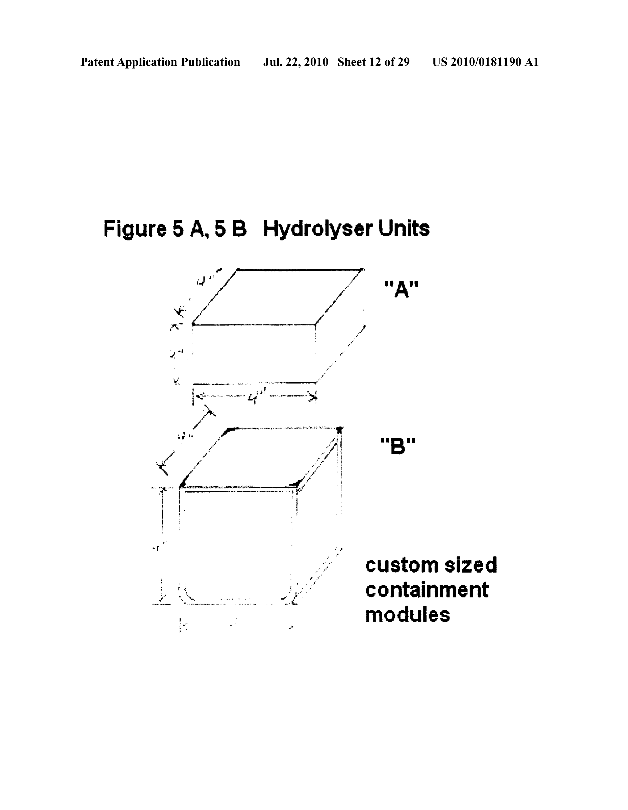
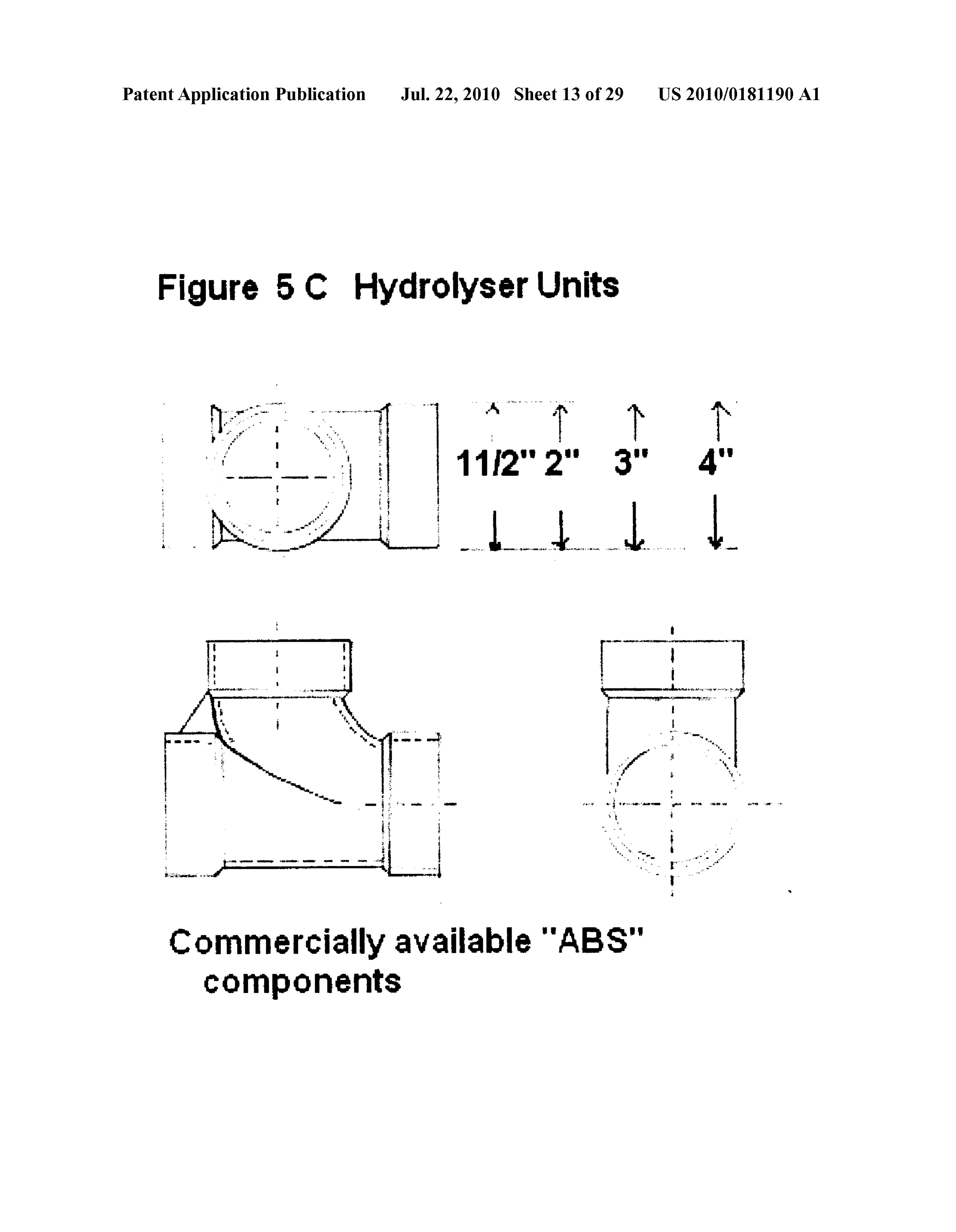
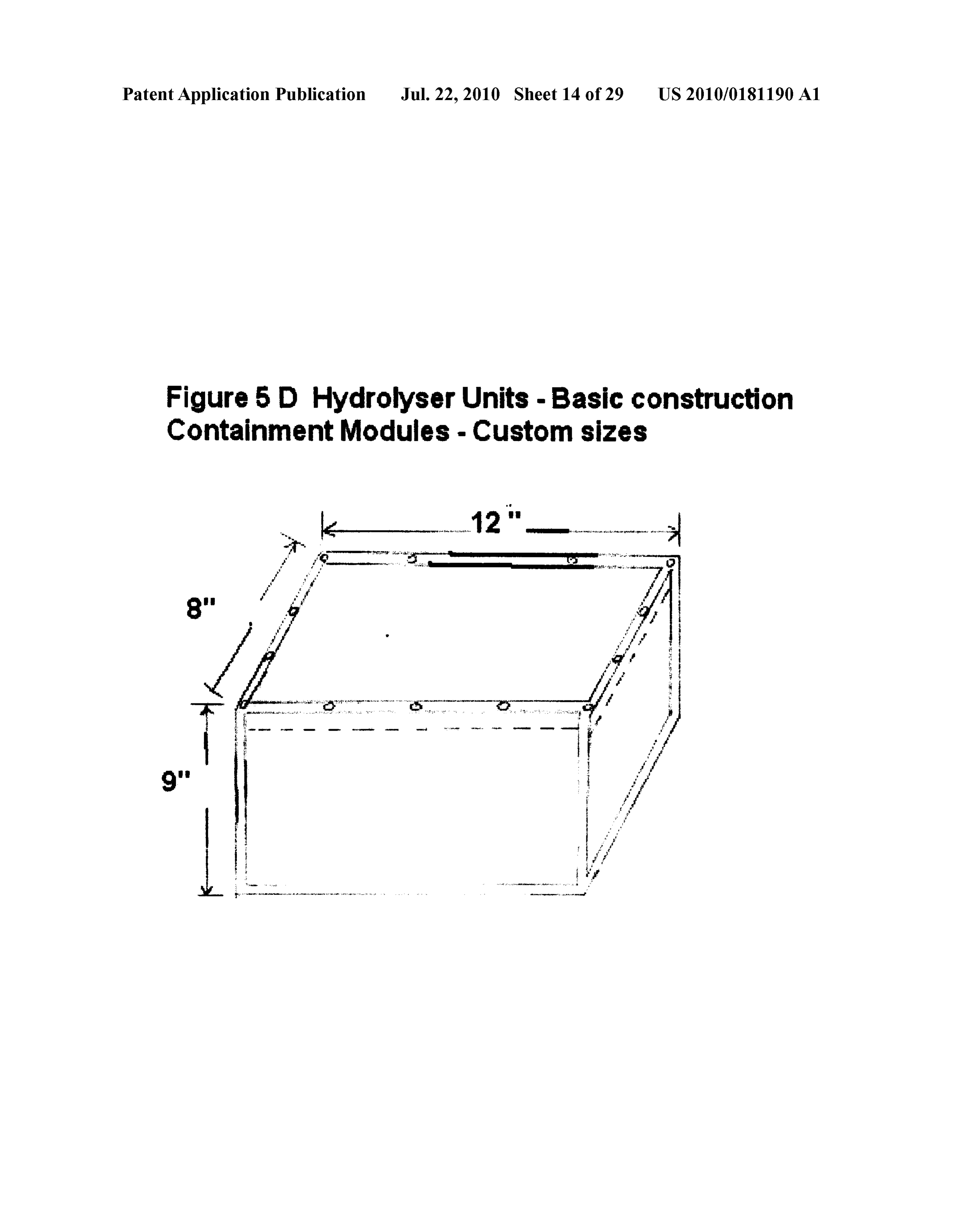
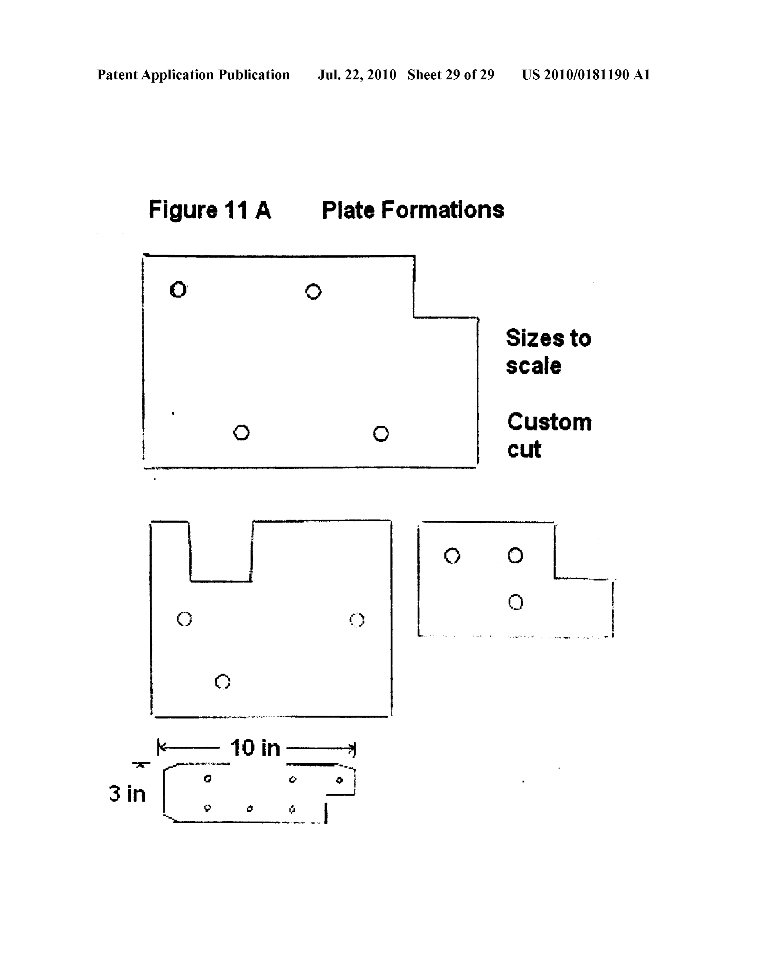
PREFERRED EMBODIMENT, SPECIFICATIONS such as nylon, polyethylene, polypropylene or UHMW but AND DETAILED DESCRIPTION not excluding any other Suitable plastic compounds having 0001 Said process consisting of the following: a neutral and inert reaction to said hydrolytic Solution 0002 (a) The process for producing hydrogen and oxygen composed of a pre-determined mixture of potassium gases as a partial fuel source for internal combustion hydroxide and distilled or demineralised water but not engines, further including one or multiple electrolyser excluding any other chemicals acting as hydrolytic agents units according to claim #12, arranged in tandem, and necessary for the process of electrolysis and which include electrically connected in parallel or in series when more but are not limited to such other hydrolytic agents such as than one unit is required for optimum engine operation. Sodium hydroxide, Sodium bicarbonate, sodium carbonate, Said containment modules (electrolyser unit/units) con Sodium citrate as examples of alternative hydrolytic Sub structed of specific non-metallic plastic compounds or stances that may be used as a hydrolytic agent. Said plates tempered glass in pre-determined shapes (cylindrical or set at a distance between the plates ideally at 0.9525 cen geometric) (FIGS.5A, 5B, 5C, 5D1,5D2) and “scaled to timetres (3/8 inch) (FIG. 10B) but not excluding any other size' as warranted by the end use, and more specifically suitable spacing, from 0.3175 centimetres (/s inch) to a including plastics made of Polypropylene, Kraylon plastic, range of up to 5.08 centimetres (2" inches), that may be ABS plastic, polyvinyl chloride (PVC), ultra high density required for optimum electrolyser performance, without weight (UHMWPE) polyethylene, ultra high density preset spacing restrictions and as such, said spacing as may polypropylene (UHDPP), but not excluding any other type be necessitated by the size of the electrolyser units and the of plastic or glass-based products suitable for said contain level of hydrogen/oxygen gas output required for optimum ment modules. Said containment modules may be manu engine performance. The plate assembly is constructed in factured to specifications by an injection-mould operation Such a way so as to create cells and install said cell assem or by an extrusion process; obtained as commercially avail blies in Such a manner as to allow said hydrolytic Solution able modules; and where necessary, said hydrolyser mod to freely flow through said containment modules and be ules may be further constructed, for certain applications, in able to completely cover the said plate assembly. The specially engineered modules made of Polypropylene metallic internal components connecting the necessary (UHMW-PP) “sheeting, in a variety of thicknesses, parts plates for an electrical current to pass are made of SS304 or cut to specifications and assembled by a plastic welding 18.8 stainless steel and include eye bolts, various type and operation to required sizes, specifications, installation sizes of bolts, nuts, washers, lock washers and stainless limitations, thickness limitations, as well as internal plate steel rods where necessary. Said stainless steel components assembly limitations, or any other pertinent criteria. Said vary in size depending on the required size of the electroly process also includes UHMW (ultra high molecular ser units. Said stainless steel components create an electri weight) Polyethylene or Polypropylene plastic pre-engi cal contact between the plates in the plate assembly, and are neered by a mechanical cavity extraction process where used as the electrical input posts, for the anode and cathode blocks or cylinders are used and when special applications connections, so as to allow DC electric current to flow are warranted, furthermore, said process shall not exclude through said plates activating the electrolysis process. any other type of plastic compounds, glass based com Internal components also include non-reactive (to the pounds, or Suitable metallic composites as may be needed hydrolytic solution) neoprene or Vulcanized rubber wash to meet specific end-use requirements. ers, and said rubberized components may include Hypolon 0003) (b) The process for producing hydrogen and oxygen rubber, in the required composition and hardness (dura), gases as a partial fuel source for internal combustion and in sizes Suitable to seal all openings in the containment engines according to claim #13 further including the inter module/modules so as to create an internally airtight con nal components of said hydrolyser units consisting of two tainment module.
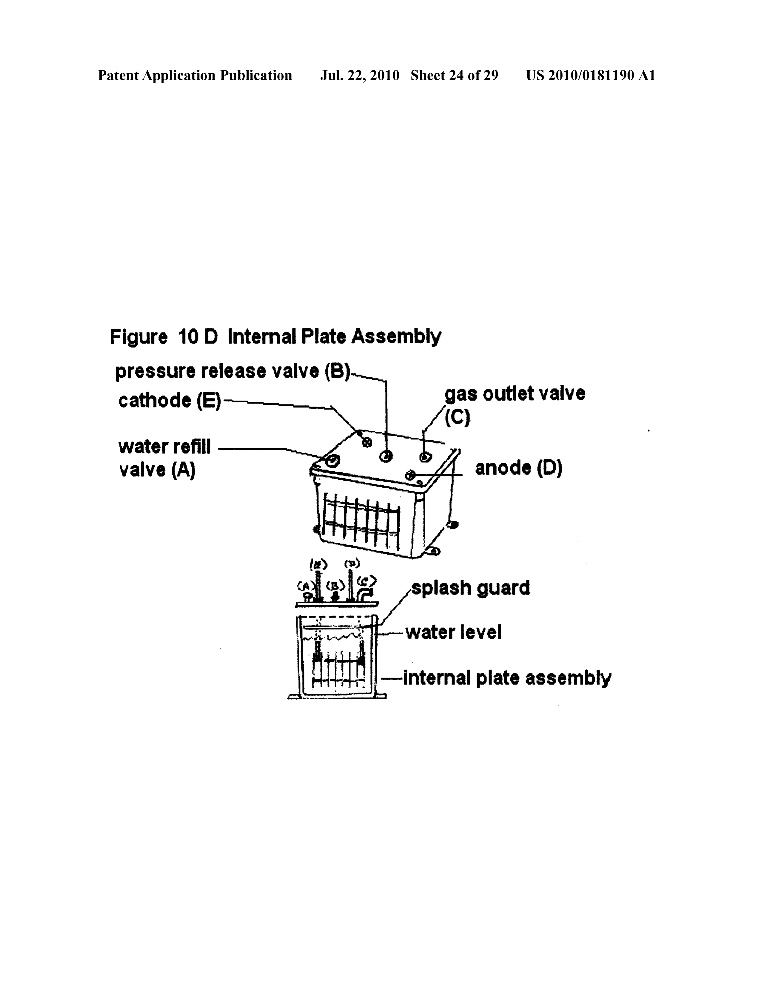
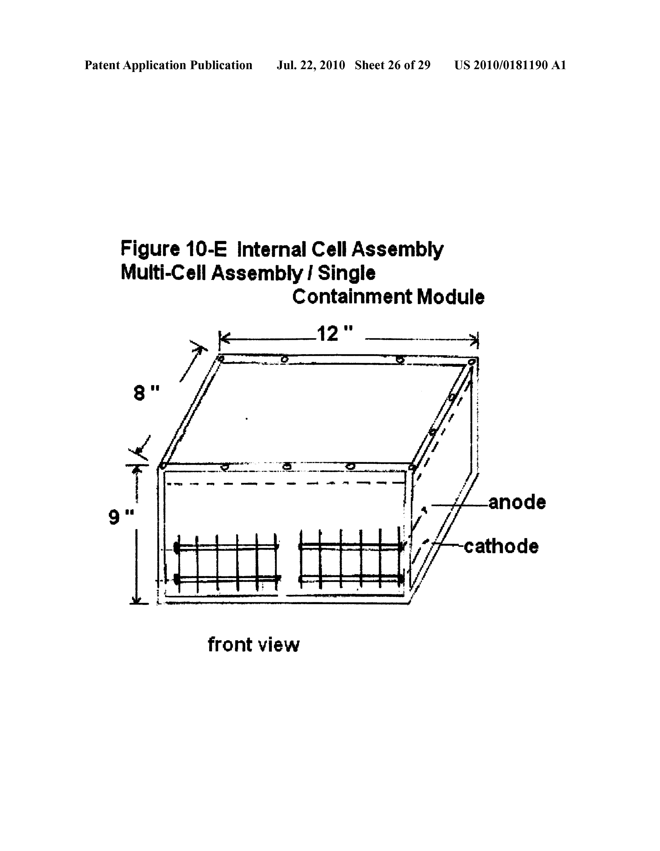
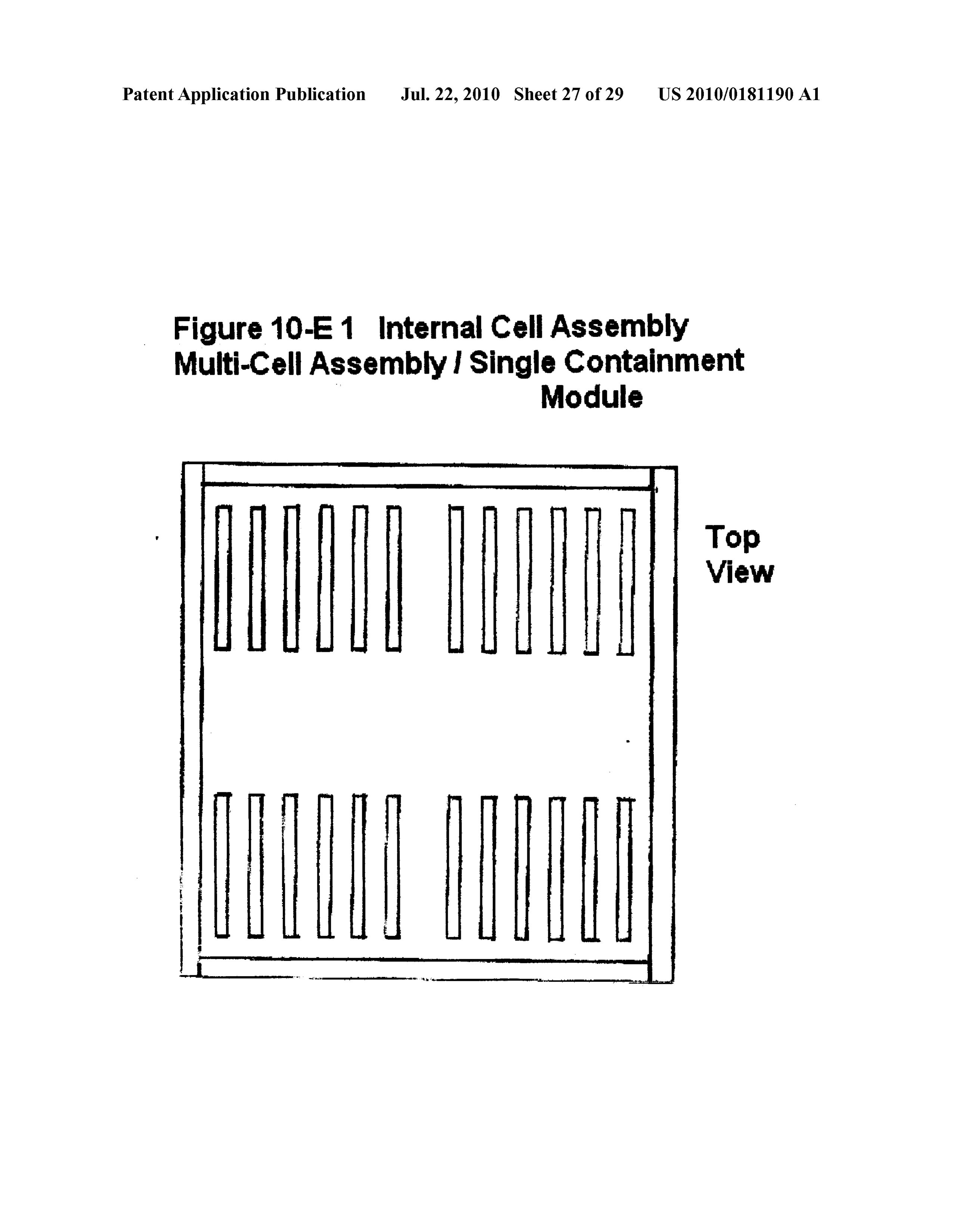
or more flat, Solid or perforated, non-magnetic stainless 0004 Said containment modules or hydrolyser unit/units steel plates (as shown in FIGS. 10A, 10B, 10C, 10D, 10D1, contain a pre-determined level of an electrolytic Solution as 10E, 10 E1, 10E2) including different types of stainless described above and further detailed, such as a mixture of steel, and more specifically, types SS304, SS306, SS310, water (steam distilled water preferable) and potassium SS314, and SS316, including variable gauges such as 16 or hydroxide (KOH) in a pre-measured concentration of 18 gauge and up to and including 24 gauge where neces between a halfpercent concentrate 0.5% to a 60% concentra sary, but not excluding any other gauge sizes or conductive tion of hydrolytic Solution level so as to produce an optimum materials as may be required, and furthermore, all of which amount of said gases and for maximum efficiency in the is determined by the size of the units required for specific operation of the unit/units but not excluding the use of any installations including the necessary shape and sizing of other type of electrolytic solution such as de-iodinated said plates as required so as to fit inside said containment sodium or a mixture of crystallized sodium bicarbonate when modules or hydrolyser unit/units according to claim #12 used in warm-weather climates. In certain applications, mul (FIGS.5A, 5B, 5C, 5D1,5D2). Said plates form the basis tiple internal plate assemblies (for example, two or more plate of the internal plate assemblies required for the production assemblies which may consist of a minimum of 2 or more of said gases and said plate assemblies constructed in vari individual plates—possibly six (6) plates per plate assembly able sizes and variable number of plates so as to optimize as shown in FIG.10E or eight (8) plates perplate assembly as
Page 32
US 2010/0181190 A1 Jul. 22, 2010
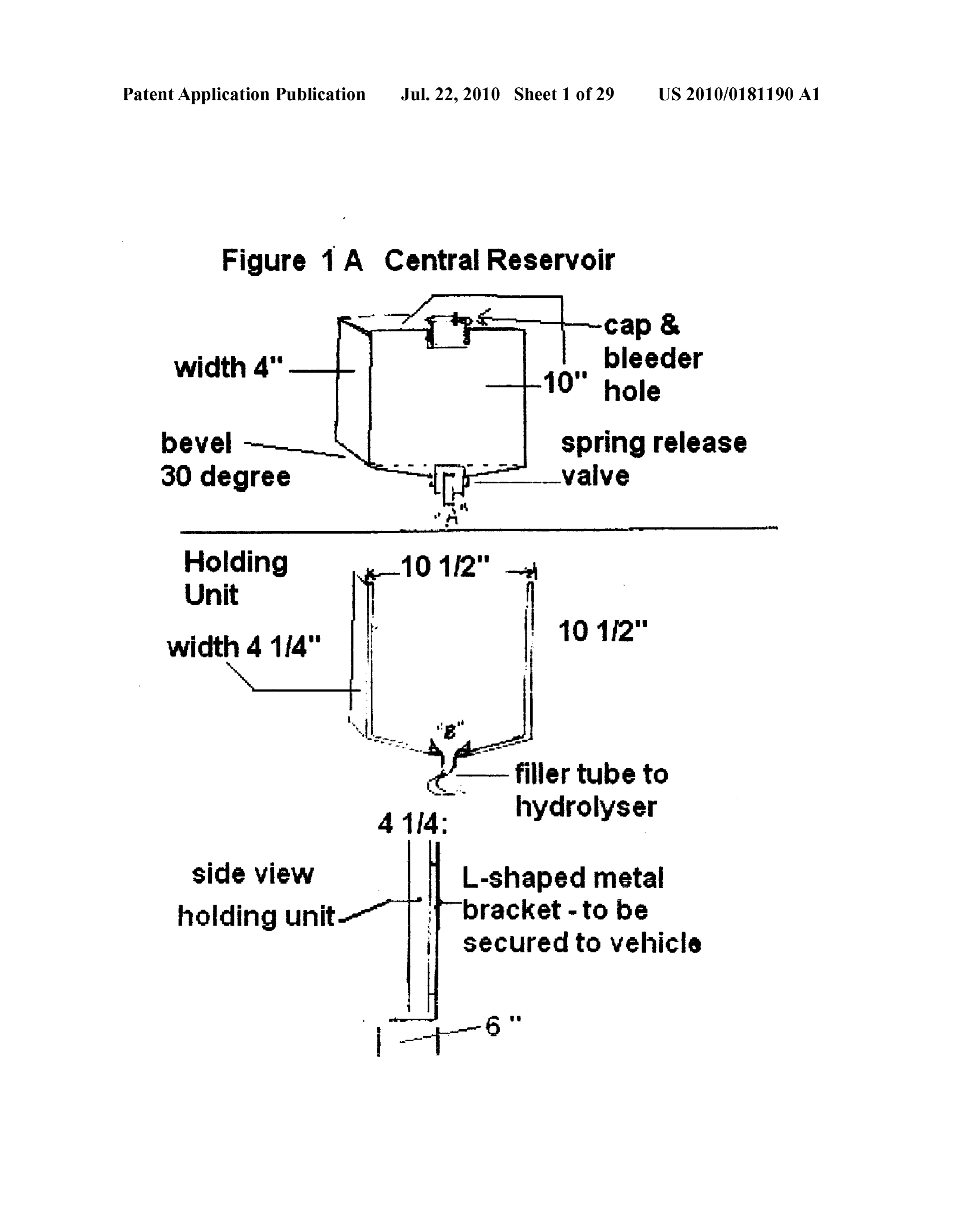
shown in FIGS. 10A and 10B) are installed in a single con insulation between the walls for use in installations in tainment module. Said plate assemblies, with multiples of cold-weather climates, using a high-heat resistant plastic two plate assemblies (FIG. 10E2) to four plate assemblies compound or metal composite for the walls. Said double (FIG. 10E1) and additional assemblies, if required, are walled reservoirs capable of withstanding an inflow of installed in a single containment module (FIG. 10E) so as to constant highly-heated liquid (anti-freeze Solution or cool maximize space, size, hydrolytic Solution, electrical input or ant) as required according to claim #2 that is heated to any other restrictions necessary for optimum efficiency. In approximately 85 degrees Centigrade (200 degrees Fahr certain applications, such as in cold-weather climates, the enheit) and to withstand extreme cold temperatures reach electrolytic Solution must have a much lower freezing tem ing minus -50 below zero centigrade temperatures so as to perature than water, allowing operations of the electrolyser withstand the freezing of said water stored inside said units to operate in Sub-Zero (0 degrees Centigrade/32 degrees reservoirs for cold-weather applications without damage to Fahrenheit and up to minus -50 degrees C./minus -70 said reservoir. Said process according to claim #1 further degrees F). temperatures. Sufficient electrolytic solution is including a custom manufactured reservoir in a single maintained at all times So as to completely cover the stainless walled construction with no added insulation using a Suit steel plates (as shown in FIGS. 10D and 10D1 as examples able plastic compound or metal composite as described above for use in warm-weather climates which is not and applicable in all versions of said hydrolyser units) so as to required for extreme heat or extreme cold applications. maintain a maximum, controlled and constant flow of said Said reservoirs custom constructed so as to fit within size gases for optimal efficiency or, at a very minimum, for partial efficiency, covering at least one half of the plate Surfaces to and shape limitations and to accommodate the water Vol maintain a partial efficiency in the operations of the hydroly ume requirements for the complete process in specific ser unit/units, should hydrolytic Solution not be maintained applications.
above the plates. Said process includes commercially avail Said reservoirs further include one of the following con able mechanical or digital float Switches as well as valves and figurations dependent on installation and size limitations: fittings in various formats required for gas delivery, water 0006 (c-i) a separate and independent central pre-filled refill entry and exit points, pressure release valves at pre water reservoir (FIGS. 1A, 2B) according to claim 1, determined PSI (pounds per square inch) settings, check together with a holding unit (FIG. 1A), and preferably with valves and, in certain applications, rupture discs. All Such steam distilled water, but not excluding de-mineralized valves and settings compatible with the electrolytic solution water or tap water, and when Such installation allows for where necessary. Also included in the process are the required said reservoir to be placed at a higher level than the elec tubing and conduits, correctly sized electrical wiring in con trolyser unit/units, allowing the water to flow downwards junction with said electrical source according to claim #5 and by gravity force through a feeder tube or multiple tubes via for power Supply packs according to claim #6, as well as a parallel system into a single hydrolyser or multiple commercially available warning lights, ammeters, Voltage hydrolyser units dependent on the end use of said process. meters, electrical connectors, water level indicator gauges or Said process used in warm-weather climates while in cold sight glasses, and thermometers where applicable. Further weather climates, this reservoir heated through a conduc more, said process includes or may include a main container tive and/or convective heat transfer system according to casing, custom made to allow all of the major components of claim 2 (FIGS. 2B2, 2B3, 3A&3B), this process further said electrolysis process to fit into its interior or be attached to including a water level control via a special valve (collec it, and may include, but not be limited to: 1) a two-piece tively shown in FIGS. 4A-1A/4A1B/4A2/4A3) according custom made, weather resistant box made of stainless steel, to claim #3 but not excluding, as a secondary function, the diamond plate steel or aluminum; 2) a modified commercially use of commercially available mechanical or digital, Ver available cylindrical or square shaped Steel gas tank specially tical or horizontal float switches together with an electri modified with cut-out access panels or 3) by a custom made cally activated solenoid switch to regulate the water levels container casing specifically constructed for said process, in said hydrolyser unit/units as may be applicable for cer allowing installation of all or most components of said com tain installations. Said special valve according to claim #3 plete process on the frame of Class 8 tractor trailer cabs for automatically maintains the proper level of hydrolytic example; further including 4) a cylindrical stainless steel Solution as water is released into said hydrolyser unit/units container casing similar to commercially available air filter from said central reservoir, when float section of said valve truck casings but custom made specifically for said process; is mechanically activated as said hydrolytic Solution level and further including 5) a custom built battery-type tray with lowers during the process of electrolysis is actively func a cover with Snap closures similar to commercially available tioning. As the process of electrolysis slowly causes the battery boxes used on semi trailer trucks. level of said hydrolytic solution to lower, refilling of said 0005 (c) The process for producing hydrogen and oxygen hydrolyser unit/units is equally and automatically main gases as a partial fuel source for internal combustion tained and controlled by said special valve. engines further including a process to refill said hydrolyser 0007 (c-ii-a) a separate and independent pre-filled water unit/units from a separate and independent water-filled reservoir (FIG. 1A, 2B) according to claim #1, preferably reservoir according to claim 1. Said independent, custom with steam distilled water, but not excluding de-mineral made water-filled reservoir specially constructed of a high ized water or tap water if necessary, that, when installation heat resistant plastic Such as polypropylene or polycarbon does not allow said reservoir to be placed at a higher level ate, but not excluding other high-heat resistant plastic than the electrolyser unit/units and whereby a gravity feed compounds, or, in a metal composite Such as stainless steel cannot be applied and when cold-weather climates are not but not excluding other heat-resistant metal (FIGS. 1A, 2B, instrumental in the efficient functioning of said refill sys 2B1, 2B2, 2B3). Furthermore, said reservoir is custom tem, the process will allow the water to flow into the elec made in a double-walled construction with an inner-foam trolyser unit/units through one or more delivery conduits,
Page 33
US 2010/0181190 A1 Jul. 22, 2010
this process utilizing a pump apparatus installed in a Suit pre-determined level as indicated by a compatible (to said able position between said reservoir and said hydrolyser hydrolytic solution) and commercially available mechani unit/units, so as to allow the flow of water, when said pump cal or digital float Switch/s, mounted inside said hydrolyser is manually activated by the user with an on/off switch and unit/units in either a horizontal or vertical position, and as determined by a water level warning light, warning when activated, sending an electronic signal, further acti gauge or sight glass as to when level of said hydrolytic Vating said Solenoid valve to open, with power from a Solution is low and a quantity of new water must be intro battery source, whereby said solenoid valve, when acti duced to refill said hydrolyser unit/units. This process used vated will allow said distilled or de-mineralized water to be in warm-weather climates while in cold-weather climates, released from the central pre-filled water reservoir so as to said reservoir will be heated through a conductive and/or maintain a pre-determined hydrolytic solution level in the convective heat transfer system according to claim 2 and hydrolyser unit/units. This process used in warm-weather this process further including a water level control via the climates while in cold-weather climates, this reservoir will special valve according to claim #3, preset at a maximum be heated through a conductive and/or convective heat water fill level in said hydrolyser unit/units, but not exclud transfer system according to claim #2. ing the use of commercially available mechanical or digital 0010 (c-iii) an atmospheric water recovery system that float Switch, in a horizontal or vertical format, so as to utilizes the process of dehumidification in a specially regulate the water levels in said hydrolyser unit/units. designed unit that will effectively remove moisture and 0008 (c-ii-b) a separate and independent pre-filled water humidity from the air through a specially constructed and reservoir (FIG. 1A, 2B) according to claim 1, preferably modified dehumidifier, and convert it to water. Said water, with steam distilled water, but not excluding de-mineral through a conduit or series of conduits, in parallel, will be ized water or tap water if necessary, that, when installation fed from the reservoir of said dehumidifier unit to the does not allow said reservoir to be placed at a higher level electrolyser unit/units. As dehumidification occurs above a than the electrolyser unit/units and whereby a gravity feed minimum of plus +5 C. degree temperature, installation of cannot be applied and when cold-weather climates are not this system is limited, in the first instance, to applications in instrumental in the efficient functioning of said refill sys warm-weather climates or in applications where heated air, tem, the process will allow the water to flow into the elec and sufficient moisture and humidity in the air is available, trolyser unit/units through one or more delivery conduits, and where installations allow for the size of the unit to be this process utilizing a pump apparatus installed in a posi used. In a secondary instance, in certain applications, said tion between the exit point of said reservoir and said heated air originates by diverting heated exhaust from the hydrolyser unit/units so as to allow the flow of distilled or exhaust assembly by introducing a separatorY-type attach de-mineralized water, when said pump is activated auto ment along the exhaust pipe, diverting one part of the matically, when said hydrolytic solution level inside the exhaust to circulate, through a series of special conduits hydrolyser unit/units drops to a pre-determined level as and said warm air made to circulate around said dehumidi indicated by a compatible (to said hydrolytic solution) and fier unit, causing a warmer air and moisture atmosphere to commercially available, mechanical or digital float Switch/ allow for dehumidification. The other part of the Y-separa Switches, mounted inside said hydrolyser unit/units in tor along said exhaust system shall be used to exhaust either a horizontal or vertical position, sending an elec normal vehicular or internal combustion engine emissions. tronic signal, further automatically activating said pump, The process may also fully utilize all of the exhaust system with power from a battery source, whereby said pump if all said exhaust gases are redirected through the area whenactivated will allow said water to be released from the where said dehumidifier unit is located so as to warm up central pre-filled water reservoir so as to maintain a pre and add humidity in the air surrounding the dehumidifier. determined hydrolytic solution level in the hydrolyser unit/ This process may be used in certain specialized applica units. This process used in warm-weather climates while in tions such as installations on trains, boats, heavy equip cold-weather climates, this reservoir will be heated ment, stationary generating stations and other Such type of through a conductive and/or convective heat transfer sys installations. The said atmospheric water recovery system tem according to claim #2. is used preferably in warm-weather climates where tem 0009 (c-ii-c) a separate and independent pre-filled water peratures of plus +5 degrees C. prevail and where mini reservoir (FIG. 1A, 2B) according to claim #1, preferably mum atmospheric humidity levels prevail. In this process, with steam distilled water, but not excluding de-mineral water derived through dehumidification is collected in a ized water or tap water if necessary, that, when installation central reservoir and redistributed via a conduit or multiple does not allow said reservoir to be placed at a higher level conduits into the hydrolyser unit/units by either a gravity than the electrolyser unit/units and where a gravity feed feed as described in (c-i) or by a mechanical pump manu cannot be applied and when cold-weather climates are not ally or automatically activated as described in (c-iia and instrumental in the efficient functioning of said refill sys c-ii b), or by an automatically activated Solenoid valve tem, the process will allow the distilled or de-mineralized switch as described in (c-ii c). In the case described in (c water to flow into the electrolyser unit/units through one or ii-a), said water level control inside the hydrolyser unit/ more delivery conduits, this process utilizing a Solenoid units will be maintained by said special valve according to valve, set in the closed position until activated, to open by claim #3 whereas in the applications described in (c-ii b) an electronic signal sent from pre-positioned float Switche? and (c-ii c) said water level control inside the hydrolyser s, said Solenoid valve installed in a position between said unit/units will be maintained by either a single or multiple, central reservoir according to claim 1 and said hydrolyser horizontally or vertically mounted, mechanical or digital unit/units so as to allow the flow of water, when said sole float Switches as certain installations may warrant. noid valve is activated automatically, when hydrolytic 0011 (c-v) a separate and independent pre-filled water solution level inside the hydrolyser unit/units drop below a reservoir, in the form of commercially available bottles or
Page 34
US 2010/0181190 A1 Jul. 22, 2010
containers, and according to claim 1, preferably with steam the opposite end of said harness around the holding appa distilled water, but not excluding de-mineralized water or ratus (FIG. 3A, 3B) of the independent water-supply res tap water if necessary, used to refill said hydrolyser units ervoir, constructed from a metallic based, highly heat manually when installations of said separate central water conductive enclosure Such as aluminum and into which the reservoirs are not practical. A manual feed into the top end independent plastic-based reservoir may be inserted and of said special valve according to claim #3 will refill said Supported by said metallic holding apparatus so as to pro hydrolyser unit/units and the proper level of hydrolytic vide sufficient heat to unfreeze or to keep the water con solution will be controlled when said special valve, tained in the water-filled reservoir from freezing in cold through the closure of the float assembly inside said valve weather installations when the vehicle is in operation and is activated and stops the water from further entering into further enabling an adequate pre-determined supply of the hydrolyser unit/units. This manually controlled process water to reach the hydrolyser unit/units. Said process to be used for Small installations, such as under the hood of used in stationary applications such as stationary electrical vehicles and where it is relatively simple to refill said generating stations (Gen-Sets). Said holding apparatus hydrolyser unit/units with a minimum requirement of covered by a similar blanket with embedded heat conduc water. A commercially available water level gauge, eithera tive wires/strapping of the opposite end of said wire assem transparent tube type model or sight glass, may be incor bly. Additional individual strands of said wiring assembly porated into the hydrolyser unit/units as an additional fea may be inserted into the tubing conduits through specially ture to visually determine when the proper level of hydro designed rubberized membranes So as to create an air tight lytic solution has been reached inside the hydrolyser unit/ entry and exit point within the assembly, this, to provide a units (note: water level gauges or sight glasses are not part conductive and convective heat Source to avoid said steam of this claim). distilled water in the conduit/conduits from freezing before 0012 (d) The process for producing hydrogen and oxygen reaching the hydrolyser units. Dependent on the size of the gases as a partial fuel source for internal combustion water reservoir and the hydrolyser units used for specific engines according to claim #2 further including a conduc installations, a correlated size of blanket, mechanically tive or convective heat transfer system, separately or engineered and constructed to effectively transfer, through together so as to use the heat generated by the engine when a conductive heat transferring process allowing for the flow said engine is operating. Sources of said heat from the of water into said hydrolyser units. The water refill delivery normal operations of an internal combustion engine system further includes one or multiple strands of conduc include the exhaust or tailpipe where hot exhaust emissions tive and convectively heated wire to be inserted into the are released into the atmosphere; the engine manifold; the special valve casing preventing said water Supply from anti-freeze or coolant generated by the radiator which is freezing in cold-climate applications and installations. heated to approximately 200 degrees Fahrenheit; and the 0014 (d-ii) The process for producing hydrogen and oxy actual exhaust emission gases. Using these sources of heat gen gases as a partial source for internal combustion through a conductive or convective heat transfer process or engines according to claim 2 further including a convective together through a joint conductive/convective heat trans heat transfer system where said water reservoir contains an fer process forms the basis of claim #2 and further includes assembly system of tubes (FIGS. 2B2, 2B3) constructed of one of the following systems. copper or stainless steel, and may include any other type of 0013 (d-i) The process for producing hydrogen and oxy tubing such as commercially available highly-heat resis gen gases as a partial fuel source for internal combustion tant rubberized tubing compatible to an anti-freeze or cool engines according to claim #2 further including a combi ant Solution and normally used in the operation of a vehicle nation conductive and convective heat transfer system radiator system. Said assembly to form a conduit system of where said hydrolyser unit/units is/are required for cold tubing through which an anti-freeze solution may be cir weather climates encompassing a system of wires or strap culated, said anti-freeze solution diverted from a vehicle's ping (FIGS. 3A, 3B) which is connected at one end to said radiator cooling system through a Y-connector or T-con independent water Supply reservoir and, at the other end to nector bypass allowing said anti-freeze Solution to circu a high heat-generating source. Such as a vehicular emission late through the heating conduits placed inside said inde tailpipe or engine manifold. Said system encompassing a pendent water reservoir and immersed in the Steam multiple number of highly conductive wires or flat strap distilled water supply but not excluding de-mineralized or ping made from aluminum, but not excluding any other tap water. Under normal vehicle operations, said anti Suitable high-heat conductive metals such as copper or freeze or coolant solution shall be heated, and when steel, and may be covered by or encased in a high-heat diverted through said assembly of conduits immersed in resistant type blanket made of either Nomex, fibreglass or said reservoir, said anti-freeze or coolant solution shall asbestos, acting as a heat insulator. One end of said assem provide heat to said distilled or de-mineralized water bly utilizes heat resistant brackets and/or straps so as to through a combination of conductive and convective heat hold said assembly around the exhaust pipe between the transfer allowing said water to be fed into said hydrolyser motor and muffler or, in certain applications around the unit/units from the central reservoir. Said reservoir casing, engine manifold, both heat Sources radiating heat under according to claim #1 and further described, in detail, in normal engine operations and heating, by conductive heat preceding section “c”, constructed of a single-walled transfer, the wire or strapping metal, said elements as may highly heat-resistant plastic compound or a metal compos be embedded in or covered by said blanket. Additionally, ite Such as stainless steel, capable of withstanding highly an insulating material Such as insulated tubing placed heated water up to 200 degrees centigrade. Furthermore, around the grouping of said wire/strapping harness along said reservoir may be constructed in a double-walled for the length of the transfer portion further insulating the mation with an insulating Substance Such as insulating harness So as to avoid any heat loss; and further connecting foam between both walls, so as to provide further insula
Page 35
US 2010/0181190 A1 Jul. 22, 2010
tion of said water reservoir for use in extreme cold-weather higher air to fuel ratio and resulting in a higher reduction of climates. Conduits transferring said anti-freeze or coolant fossil-based fuels while maintaining an effective operation fluid from said radiator source to said reservoir are con of said engine.
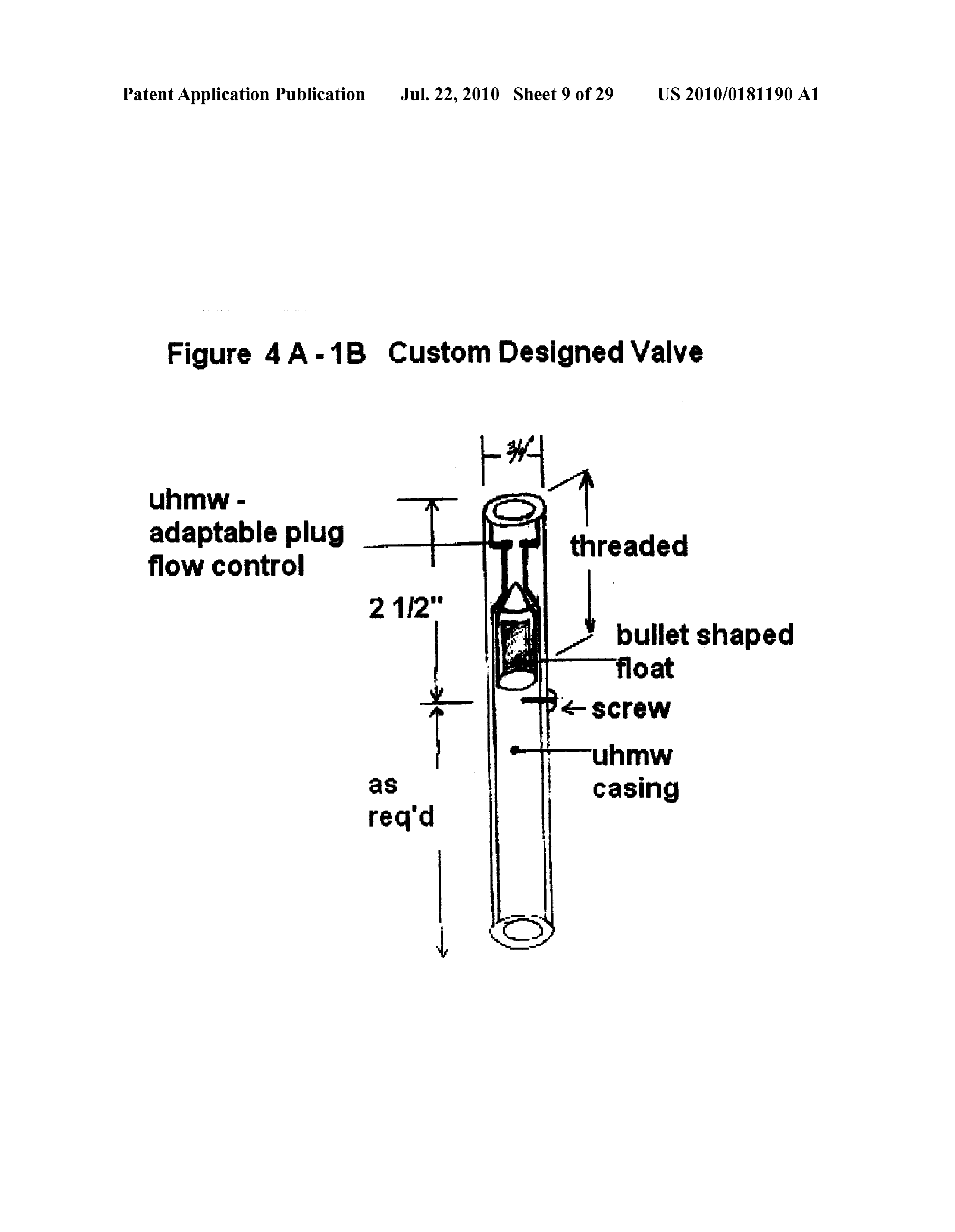
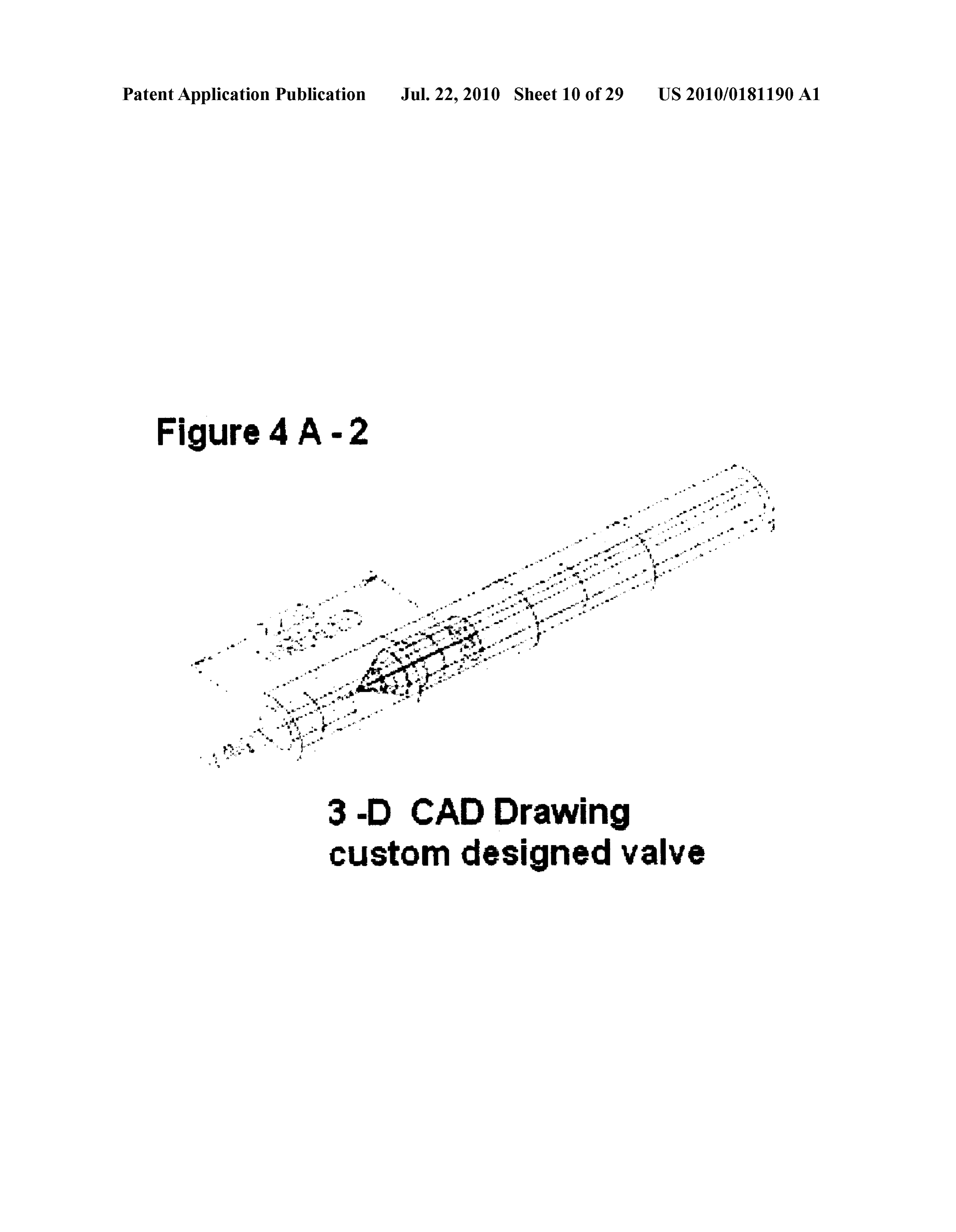
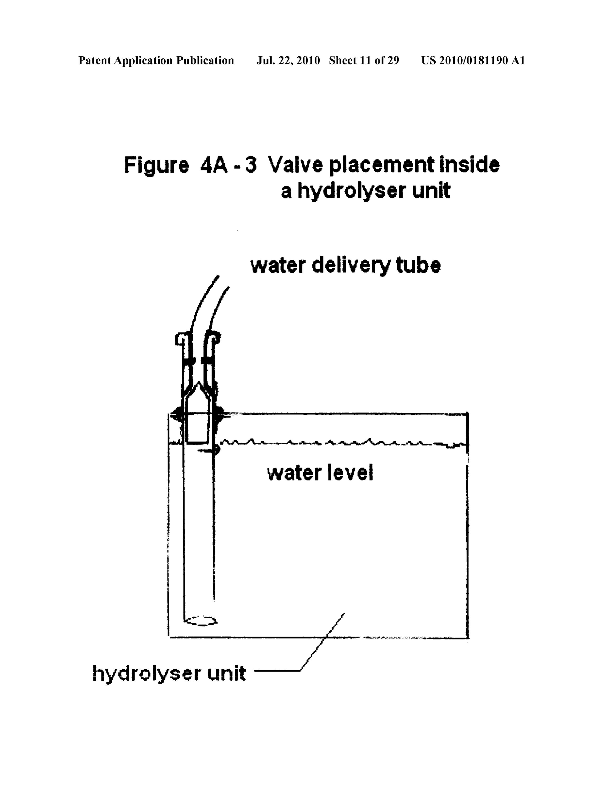
structed of copper tubing, stainless steel tubing, high-heat 0017 (f) The process for producing hydrogen and oxygen resistant rubber-based tubing or specially adapted and gases as a partial fuel Source for internal combustion commercially available hoses designed and compatible for engines according to claim #8 further including a custom use with heated anti-freeze or coolant solutions. All con ized splash guard device (FIGS. 7A1, 7A2, 7B) to prevent necters similarly constructed of Substances adapted to the hydrolytic solution from Swishing back and forth in highly heated anti freeze or coolant Solutions, the forego moving vehicular applications with additional adjustments ing all commercially available. necessary for marine vehicles or vertical movement appli 00.15 (d-iii) The process for producing hydrogen and oxy cations. Said splashguard device comprising a customized gen gases as a partial fuel source for internal combustion UHMW plastic ring, custom Vulcanized or neoprene rub engines according to claim 2 further including a double ber washers, a suitable number of stainless steel #18.8 bolts, washers, lock washer and nuts to connect said com walled insulated metal container, capable of withstanding ponents. Said splash guard device constructed in Such a highly-heated water and into which a commercially avail manner so as to allow said hydrogen and oxygen gases to able heating element is inserted. Said element to be heated flow through to the gas outlet valve but limit the amount of by a separate and independent electrical source according hydrolytic Solution in passing through the Splash guard to claim #5, such as an auxiliary 12 or 24 volt direct current device and preventing the electrolytic Solution from reach battery and recharging system and converting said direct ing said gas outlet valve. A simplified splash guard con current electrical energy into alternating current using a sisting of a solid UHMW or Polypropylene in a solid or commercially available inverter. Said process designed in perforated format, said plastic shield strategically placed in Such a manner as to unfreeze water stored in said reservoir Such a position within the containment module so as said for use in cold-weather applications when heating element hydrolytic solution is deflected away from said gas outlet is activated and designated for larger installations such as valve/valves and so as said hydrolytic solution will not stationary electrical generating stations or heavy machin enter into said gas outlet valve?valves specifically adapt ery. In the circumstance of stationary generating stations, able for applications where smaller unit/units are utilized. the electrical current produced by said Gen-Set may be 0018 (g) The process for producing hydrogen and oxygen output in an alternating current mode and therefore said gases as a partial fuel source for internal combustion heating element may receive the required electrical energy engines according to claim #3 further including a specially from the Gen-Set operation and said heating element may engineered, customized and scalable valve/valves (FIGS. be based on an alternating current eliminating the need for 4A-1a, 4A-1b. 4A2, 4A3) made of a chemical resistant an initial direct current electrical energy source from the plastic such as UHMW, ABS, polyethylene, polypropylene battery and the use of an inverter. or Kraylon but not excluding any other type of inert plastic 0016 (e) The process for producing hydrogen and oxygen compatible for use with said hydrolytic solution that main tains a pre-determined fill level of the hydrolytic solution in gases as a partial fuel source for internal combustion the hydrolyser unit/units, and including either a ball, stem engines according to claim #9 further including a central, or bullet shaped float made of a high density Vulcanized mechanically induced low pressure gas relay device (FIG. rubber compound (Hypolon), but not excluding a UHMW 8A) with one or several conduits transferring said gases stem or bullet shaped float with a polypropylene foam or from the hydrolyser unit/units into a single relay device polyethylene foam insert to achieve maximum floatation, constructed ideally from ABS plastic but not limited to and, not excluding any other type of product that is chemi ABS plastic and may include other plastic-based materials cal resistant to said hydrolytic solution and having a den such as Polypropylene or metallic construction with the sity of 0.9 (water having a density of 1) or lower than the main criteria for said gas relay device to be air tight. Said density of said hydrolytic solution so as to be buoyant in device allowing for multiple input conduits and one-way said hydrolytic solution. The purpose of said valve is to check valves at one end and a single or multiple output maintain an adequate water level within the hydrolyser conduits and one-way check valve/valves at the other end unit/units for maximum gas production. The construction for transferring said gases collected in the central gas relay of said valve is such that it mechanically regulates water unit from one or from a series of hydrolyser units, and then flow into the hydrolyser unit/units at a very slow rate, in transferring said gases, via a single or multiple conduits, proportion to the decreasing levels of the electrolyte solu into the air intake system of the internal combustion engine tion as the process of electrolysis itself slowly lowers the and Subsequently into the combustion chambers of said level of the electrolyte solution while maintaining the same internal combustion engine, creating a mechanical pres KOH concentration. Distilled or de-mineralized water is Sure whereby one or several conduits transferring said passed through said valve from the central water-filled gases from the hydrolyser unit/units into the gas relay reservoir according to claim #1 either through a gravity system at low pressures and, in certain applications and feed and include the variants according to sections (c-i)and installations, dependent on the size of said hydrolyser unit/ (c-ii a) or by a manual feed as described in section (c-V). units, less than one atmosphere of pressure of said gases is 0019 (h) The process for producing hydrogen and oxygen delivered into said gas relay device, while the exiting con gases as a partial fuel Source for internal combustion duit/s shall be of a smaller diameter or in less numbers as engines according to claim #4 further including the capac compared to the intake conduits creating a quasi mechani ity to scale up or scale down the size of said electrolyser cal turbo-type effect increasing the pressure of said gases unit/units (FIGS. 5A, 5B, 5C, 5D, 5D1, 5D2, 1A) to entering into the combustion chambers resulting in a accommodate the intended application and installation
Page 36
US 2010/0181190 A1 Jul. 22, 2010
requirements and taking into account the amount of hydro generated from the crankshaft of the motor in a vehicle, gen/oxygen gases that must be manufactured through the with said secondary alternator set in Such a manner that process of electrolysis to effectively create a partial fuel would exclusively and independently recharge said inde source that, when combined with any other fossil-based pendent auxiliary battery as an added accessory and, as fuel, reduces the amount of said fossil-based fuel normally Such, the electrical power being generated and required for required to operate said internal combustion engine and the process of electrolysis will be produced directly from replacing Such energy required with said hydrogen/oxygen one of the two said alternators of the dual alternator set-up gases to fuel and effectively operate an internal combustion and further regulated by a specially engineered power Sup engine and increasing torque and horsepower. Scaling ply pack or commercially available Voltage regulator, includes variables in sizes of said hydrolyser units from which will regulate a specified Voltage/amperage, for 10.16 cm x 10.16 cmx5.08 cm (4"x4"x2") as an example of safely maximizing the production of said gases within the a small size, and 91.44 cmx76.2 cmx50.8 cm (36'x30"x electrolyser unit/units, said power Supply enclosed in a 20") as an example of the large size unit, both as examples weather-proof box. This process eliminates the use of the of geometrically-shaped formats but not excluding Such vehicle's own battery and alternator and provides for a sizes in cylindrical formats, and furthermore, not exclud completely independent electrical source for the electroly ing said component modules not being limited to said sizes, sis process according to claim #5. but dependent on the application and installation limita 0023 (k-ii) The process for producing hydrogen and oxy tions. The intention of said scaled units is to have the gen gases as a partial fuel source for internal combustion capacity to install the process under the hood of a small engines according to claim #5 further including an inde vehicle or any application limited by available space and pendent electrical power Source in the form of a single installation restrictions and including Scaling up to instal alternator with a double pulley that when said alternator is lations on locomotives, boats, heavy mining, forestry or activated by a single belt drive from the engine crankshaft, farming equipment and stationary generating stations as the second pulley shall be installed so as to generate an examples for installation of said process where larger independent electrical current and controlled by a power energy requirements are necessary. Supply pack or commercially available Voltage regulator So 0020 (i) The process for producing hydrogen and oxygen as to deliver the properamount of DC electrical current to gases as a partial fuel source for internal combustion the hydrolyser unit/units. This process geared primarily, engines according to claim #5 further including an inde but not exclusively, for stationary generating electrical sta pendent and dedicated electrical power source in the form tions and larger installations.
of a commercially available auxiliary battery in the 0024 (1) The process for producing hydrogen and oxygen required Voltage/amperage for applications in down-scaled gases as a partial fuel Source for internal combustion or up-scaled sized unit/units according to claim #4 and engines according to claim #6 further including a manually controlled by a specially engineered power Supply pack adjustable custom made power Supply pack that sets and according to claim #6 regulating the electrical output for regulates the required amount of electrical current required safely maximizing the production of said gases within the for the process of electrolysis in the production of hydro electrolyser unit/units, with recharging of said battery by a gen and oxygen gases.
traditional alternator System, said power Supply enclosed 0025 (m) The process for producing hydrogen and oxy in a weather-proof containment box where installations gen gases as a partial fuel source for internal combustion Warrant.
engines according to claim #6 further including a variable 0021 () The process for producing hydrogen and oxygen power Supply pack or commercially available variable gases as a partial fuel source for internal combustion Voltage regulator that automatically regulates the amount engines according to claim #5 further including an inde of electrical current required for the production of hydro pendent and dedicated electrical power source in the form gen and oxygen gases by the process of electrolysis. Said of a commercially available auxiliary battery in the power Supply pack or said Voltage regulator is activated required Voltage/amperage for applications in Scaled units and controlled by the driver's throttle control foot pedal according to claim #4 and controlled by a commercially when operator steps on the gas pedal and increases or available “battery isolator', which allows for the recharg decreases the speed of said vehicle, allowing adjustment of ing of two or more separate batteries by a traditional alter the injector openings and automatically adjusting the nator recharging system encompassing one or more alter amount of fossil-based fuel to enter the combustion cham nators as required, and together with a specially designed bers. Said adjustable Voltage regulator and multi-func power Supply pack, regulating the electrical output for tional power Supply pack is constructed so as to automati safely maximizing the production of said gases within the cally increase or decrease the electrical amperage and is electrolyser unit/units. Use of said battery isolators and directly controlled and correlated by the driver's throttle alternator recharging systems bypasses the use of a vehi control foot pedal when operator steps on the gas pedal and cle's own battery and as such becomes a dedicated inde increases or decreases the speed of said vehicle. Reduction pendent electrical power source according to claim #5. or increase in the amount of the required fossil-based fuel Said process ideally designated for installations that controlled by the vehicle's computer sends a signal that require more electrical energy that regular batteries within adjusts the timing of the injector openings, and conversely a vehicle can produce. adjusts the amount of hydrogen/oxygen gases entering into 0022) (k-i) The process for producing hydrogen and oxy the combustion chamber, Subsequently adjusting the nor gen gases as a partial fuel source for internal combustion mally required amount of fossil-based fuel to enter into the engines according to claim #5 further including an inde combustion chambers of the internal combustion engine by pendent electrical power source in the form of a dual alter allowing for shorter or longer time opening sequences of nator set-up and activated by a single drive belt with power the fuel injectors, measured in milliseconds, permitting the
Page 37
US 2010/0181190 A1 Jul. 22, 2010
effective operation of said engine. Said adjustable power gases maintain or increase torque, horsepower and octane Supply further includes a rheostat type device designed in levels by replacing the reduced quantity of fossil-based Such a manner as to control the amount of amperage output fuels. This process allows for less fossil-based fuels having the capacity to regulate the amperage and con required for efficient engine performance with said reduc versely, the amount of hydrogen/oxygen gases generated tion of said fuels replaced with said hydrogen/oxygen and delivered into said hydrolyser unit/units by activating gases produced by electrolysis as apartial fuel Source while one or more in series of said power Supplies, this process maintaining engine efficiency.
controlled and activated by the foot pressure of the driver 0029 (q) The process for producing hydrogen and oxygen on the gas pedal and throttle control and in direct relation to gases as a partial fuel Source for internal combustion the speed of the vehicle directly related and controlled by engines according to claim #14 further including a com the RPMs required for maintaining speed at optimum puter-based system for measuring the output of greenhouse engine performance and further includes adjustment to the gas emissions and measured against a pre-determined "duty cycle' of the vehicle's injector valves controlling the baseline so as to evaluate and quantify the emissions being flow of fossil-based fuel into the combustion chambers. reduced to which green credits may be applied and whereas Said power Supply or Voltage regulator enclosed in a said credits for reducing said greenhouse gases individu weather-proof box, when necessary. ally or under the heading of CO2e (carbon dioxide equiva 0026 (n) The process for producing hydrogen and oxygen lent) wherever said emission reduction credits may be gases as a partial fuel source for internal combustion applicable on credit exchanges. Said process to include engines according to claim #7 further including a dust and mobile emission measuring sensors to be placed in a clus dirt filter apparatus (FIG. 6) required for specific installa ter or suitable position on board a vehicle within the tions of the hydrolyser units where high levels of dirt and exhaust assembly of said vehicles for measuring “mobile road dust or other similar conditions prevail. Said filter emission reductions”. Furthermore, where applicable, said apparatus comprising a shield made of metal or plastic, emission measuring devices include installation in Station covering an air duct on the exterior side panel of the main ary applications where said reduction of emissions shall container casing including a dust and dirt filter insert. warrant quantification by a recognized government body or 0027 (o) The process for producing hydrogen and oxygen trading entity. Said process capable of measuring baselines gases as a partial fuel source for internal combustion as well as emission reductions in a mobile or stationary engines according to claim #10 further including a manu application. Recording of said emission reductions shall be ally dischargeable, moisture build-up collector unit (FIG. recorded and saved in a pre-programmed computer pro 9) to eliminate excess moisture build up in the electrolyser gram. Said results shall then be transferred to a central unit/units and in the conduits of the electrolyser unit/units. computer via an on-board GPS system where available or Said moisture collector unit located in a position along the via a download of said data from a memory based data conduit between the hydrolyser unit/units and the air intake gathering device and transferred into a central system assembly system in certain applications and installations where said system is qualified to measure and determine but does not exclude installation along the conduit/con quantified values of green credits for trading on world duits between the hydrolyser unit/units and the gas relay credit exchanges.
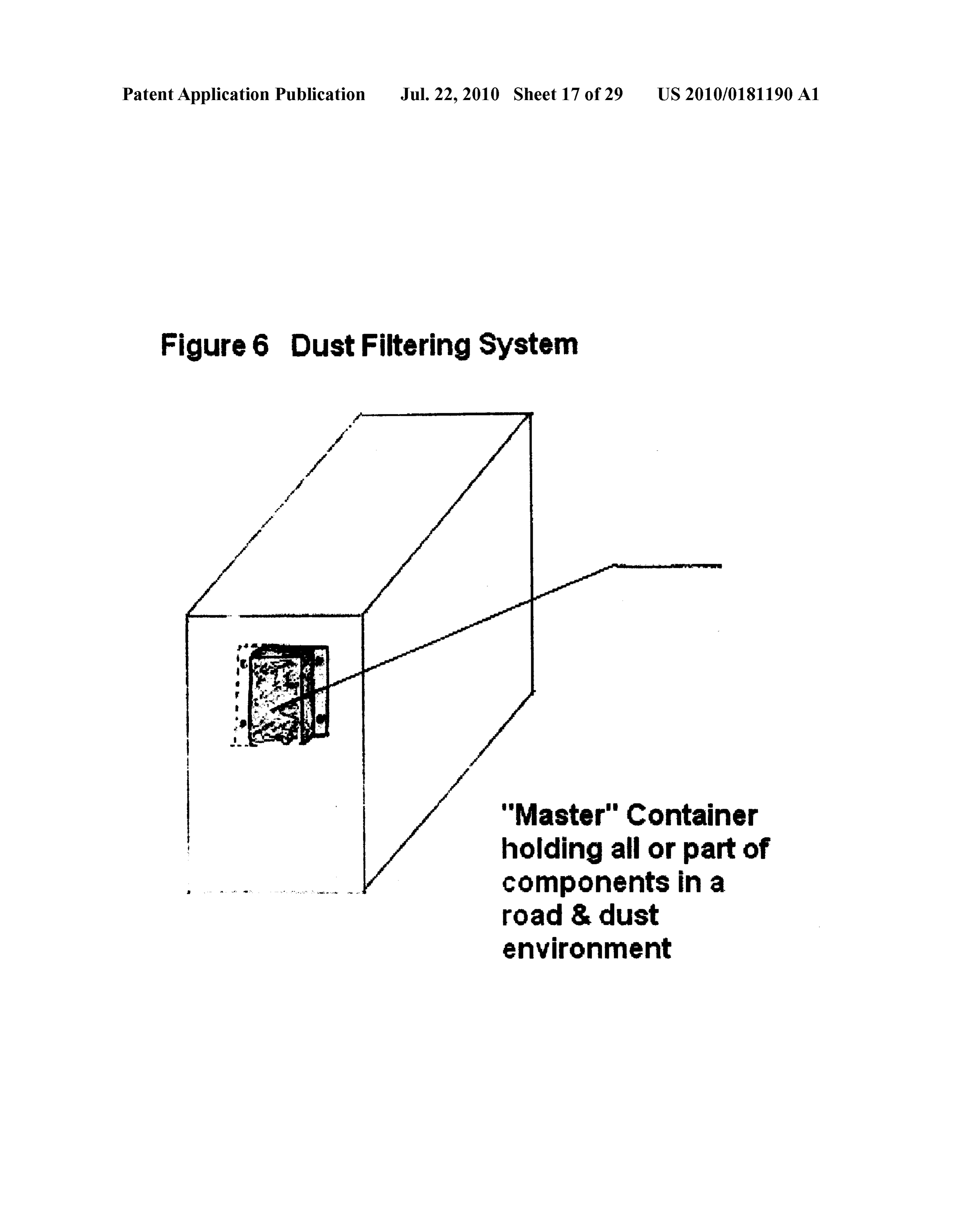
device according to claim #9 where applicable. Said mois FIELD OF THE INVENTION ture collector unit/units to contain an absorbent or deflec tive filtering Substance that can trap moisture and excess 0030 This invention relates to a complete system for pro dried-out hydrolytic solution that results from atmospheric viding a partial hybrid fuel source for internal combustion temperature variations and condensation in the operations engines (ICEs) and in particular, producing Sufficient of said process. Said moisture collector unit specially con amounts of hydrogen and oxygen gases through electrolysis structed from a plastic (ABS plastic) or metal composite, So as to partially fuel ICEs. Introducing hydrogen/oxygen pressure sealed, to allow an input and output for the gases gases as a partial fuel Source into the combustion process as well as a drain outlet or drain valve so as to easily drain results in a decrease in the consumption of fossil-based fuels, said unit with said accumulated moisture and so as to easily greenhouse gas emissions and air pollution. replace the disposable filtering Substance.
0028 (p) The process for producing hydrogen and oxygen BACKGROUND OF THE INVENTION gases as a partial fuel source for internal combustion engines according to claim #11 further including a manual 0031 Numerous patents currently exist that use hydrogen/ adjustment and/or replacement of the resistance in the oxygen gases produced by electrolysis as an enhancement vehicle's computer so as to alter the “duty cycle' and more agent or a Supplemental additive to fuels such as gasoline and specifically the opening and closing of the timing sequence diesel fuel including propane and natural gas. While current of the fuel injector openings that controls the flow of fossil internal combustion engines have a very high degree of effi based fuel into the combustion chambers of the internal ciency, the need for huge new Sources of fossil-based fuels to combustion engine. Shorter opening sequences of said power the ever increasing number of vehicles on the planet injector openings result in the reduction of said fossil and the ever increasing need for stationary generating stations based fuel and Vice-versa, longer opening sequences result powered by fossil fuels to produce electricity has resulted in in more fuel entering the combustion chambers. Introduc world-wide problems such as global warming, climate ing hydrogen and oxygen gases into the combustion cham change, global dimming, air pollution, increases in Smog ber will result in a more complete combustion burn by levels causing respiratory problems, increase in the number raising the air to fuel ratio and results in a faster and more of weather-related natural disasters, accelerated extinction of complete burn of the fossil-based fuel by increasing the animal and plant species, melting of polar ice caps, as efficiency of the combustion, and at the same time, said examples caused by the production of carbon dioxide from
Page 38
US 2010/0181190 A1 Jul. 22, 2010
the combustion of fossil-based fuels. With the position of major oil Suppliers, some having reached a level of peak oil'. -continued and with governments around the world attempting to find
Solutions for their future energy requirements, and with Date: Patent No. Country Inventor diminishing oil reserves and ever escalating prices of existing February 1979 4,140,090 US Lindberg oil production, it has become absolutely imperative to find an May 1979 105.3606 CA alternative to using oil as an energy source or at best, 'sig December 1979 4,180,445 US Bennett &al nificantly reducing the consumption of fossil fuels' to fulfill February 1980 10724.92 CA
current and future energy needs. While newer technologies December 1980 1092S46 CA Such as hybrids, fuel cells, wind power, Solar power, wave 1098482 CA power, bio-diesel, bio-gas, ethanol blend fuels, highly-pres 1098485
US Aylward
Sured hydrogen gas, propane or natural gas and other tech 4,271,793 US Valdespino nologies are currently available, all these technologies have 4,332,219 US Gonzalez an overall, long term negative impact on the environment or 4,344,831 US Weber are not economically viable alternatives. The principal objec anuary 1983 4,368,696 US Reinhardt tive of this invention is to provide a complete system that is anuary 1983 4,369,737 US Sanders &al
easy to use and financially viable for use by all segments of 4,382,845 US Hubred the mass market to reduce the use of fossil-based fuel con 4,382,849 US Spicer Sumption and conversely, reduce carbon dioxide and other S8-10781S P
greenhouse gas emissions. As outlined in the "CLAIMS'. April 1984 4,442,801 US Glynn & al several new and innovative components have been incorpo uly 1984 117O3O8 CA rated so as to provide a complete process that will allow October 1984 4,474,612 US Lohrberg hydrogen and oxygen gases produced by electrolysis to be October 1984 O122472 used as a partial fuel source in applications where internal uly 1985 1189886 CA une 1986 4,595,477 US Detournay & al combustion engines are used taking into account climatic November 1986 4,620,915 US Ohlin conditions as well as effective, viable and economical con October 1987 4,702,894 US Cornish siderations. Furthermore, the novelty aspect of this invention April 1988 1234774 CA is based on the fact that several components encompassing May 1988 1236424 CA
this invention, as claimed in the specifications within this August 1988 4,763,610 US Thomas application, include the ability to Scale the process, into September 1988 4,773.981 US Bidwell Smaller or larger assemblies, so as to have the versatility to October 1989 4,875,988 US Aragon
adapt and to allow installation of the process to most market January 1991 O405919 segments, including the ability of extending the operating June 1991 4037541 DE time between fill-ups of the containment module and the September 1991 1289506 CA ability to operate in cold-weather climates. January 1992 5,082,544 US Willey & al April 1992 5,105,773 US Cunningham & all 0032 Reference is made to the following patents, prior art June 1992 5,119,768 US Russel on record and in the public domain. The objective of this September 1992 5,143,025 US Munday patent is to add new innovative components as presented in January 1993
March 1993
Nakamats
Munday the "CLAIMS' so as to use the process of producing hydro 5,196,104
gen and oxygen gases, from the electrolysis of water, as a February 1994 214188O CA partial fuel Source for internal combustion engines. March 1994 5,293,857 US Meyer
Patent Documents and Other References Cited as Follows: September 1995 2184995 CA
0033 September 1995 5,452,688 US Rose
Date: Patent No. Country Inventor October 1998 5,824,202 US Fabian &al
December 1944 2,365,330 US Carmichael anuary 2000 2244O22 CA January 1945 2,373,032 US Klein anuary 2000 2278917 CA May 1950 2,509,498 US Heyl February 2000 OOO6875 WO August 1951 2,565,068 US Drabold October 2000 6,126,794 US Chambers April 1966 732594 CA April 2001 6,209,493 US Ross March 1972 3,648,668 US Pacheco uly 2001 6,257,175 US Mosher &al February 1976 3,939,806 US Bradley November 2001 6,311,648 US Laroque September 1976 3,980,053 US Horvath December 2001 6,332,434 US De Souza etal January 1977 4,003,204 US Bradley anuary 2002 6,336,430 US De Souza etal March 1977 52-027919 P une 2001 2001 OOO3276 US De Souza May 1977 4,023,545 US Mosher & all February 2003 6,524,453 US De Souza &al June 1977 4,031,865 US Dufour February 2004 2004f0O2S807 US Jhetham July 1977 4,035,255 US Gritzner 6,817,320 US Balan &al October 1977 4,054,423 US Blenman 6,896,789 US Ross April 1978 4,085,709 US Tangri 2OOSO1265.15 US Balan &al May 1978 4,090,485 US LaCreta February 2006 PCTUS2006 OOS298 Monette July 1978 409,989 US Bradley March 2006 PCTCA2006.OOO4S4 Bogers, Williams September 1978 4,111,160 US Talenti April 2006 PCT/US 2006/O13530 Boyle
Page 39
US 2010/0181190 A1 Jul. 22, 2010
-continued 0040 Marine sector small, medium and large boats and marine vehicles
Date: Patent No. Country Inventor 0041 Mining sector—large mining vehicles and equip April 2006 7,021,249 US Christison ment, machinery used in underground mines, tar sands December 2006 7,143,722 US Ross production (vehicles and generating stations) April 2007 2007.OO7468O US Ross 0042 Farming sector—tractors, combines and all types
Hernandez and sizes of farming vehicles
January 2007 PCTCA2007.OOO12S Lindsay 0043 Warehousing operations—propane and natural gas January 2007 PCTCA2007.OOO126 Lindsay powered fork-lift trucks
January 2007 PCTCA2007 OOO127 O'Bireck, 0044 Energy sector Stationary gasoline or diesel pow Basra, Doughty
March 2007 PCTES2007 OOO110 Gaig Gomez ered electric generating stations (Gen-Sets) April 2007 PCT/US 2007 OO9591 Smola, Schubert What is claimed is:
May 2007 PCTUS2007 OO10934 Vanhoose, Goens 1: Consists of a method of use of an apparatus referred to as a hydrolyser unit, for the production of hydrogen and oxygen gases by means of electrolysis and Subsequent delivery sys
OTHER REFERENCES tem, of the resulting hydrogen and oxygen gases, to be 0034) Dynamic Fuels Systems Inc. and Canadian Hydro installed into the air intake system of existing internal com gen Energy Company Ltd. “Statement of Claim filed bustion engines, for use as a partial fuel source when added to Jul. 12, 2004, Federal Court of Canada Court File No: the fossil-based fuels used in the operation of any internal T-1297-04 combustion engine in applications such as in motor vehicles 0035. Dynamic Fuels Systems Inc. and Canadian Hydro or stationary applications, which use internal combustion engines, such as stationary electrical generating stations gen Energy Company Ltd. "Amended Statement of (Gen-Sets), the hydrolyser unit and delivery system com Claim filed Sep. 8, 2004, Federal Court of Canada— prised of:
Court File No: T-1297-04 a hydrolysis chamber, the hydrolysis chamber being a
SUMMARY OF THE INVENTION cubicle enclosure functioning as a containment module, fabricated in a plastic-based compound, and compatible with an electrolytic solution, constructed in scalable and “Hydrogen and Oxygen Gases, Produced On-Demand by proportional sizes and formats So as to accommodate Electrolysis, as a Partial Hybrid Fuel Source for Internal installation for end-use requirements, having a remov Combustion Engines.” able access panel in order to perform regular mainte 0036) A process, based on the electrolysis of water, pro nance of the internal plate assemblies, other internal ducing hydrogen and oxygen gases, on-demand and in certain components and maintenance of the electrolytic solu applications such as on-board vehicles, and including station tion;
ary applications such as in stationary generating stations a water-based electrolytic solution comprised of steam dis (Gen-Sets), and all, without requiring highly pressurized tilled water, demineralised water or regular municipally hydrogen storage tanks, with said gases becoming a partial Supplied tap water, together with an electrolytic agent fuel source by partially reducing the amount of fossil-based Such as potassium hydroxide, to activate the process of fuel originally required to power an internal combustion electrolysis, when a direct current (DC) electrical charge engine, the process, by enriching, with the use of hydrogen/ is introduced, the electrolytic solution acting as a cata oxygen gases, the air to fuel mix ratio, causing a more effi lyst for the electrolysis process; the electrolytic solution cient combustion burn effectively resulting in usingless of the partially filling the hydrolyser containment module so as fossil-based fuel required and replacing said reduction of to cover the internal plate assemblies to maximize pro fossil-based fuels with hydrogen and oxygen gases created duction of hydrogen and oxygen gases, and Such that the through the electrolysis of water in specially designed elec hydrogen and oxygen gases formed shall have adequate trolyser units. Consequently, the process of reducing fossil space above the level of the electrolytic solution within based fuel consumption shall furthermore directly reduce the hydrolyser module, for dissemination into a tube emissions in various percentages of the mass or the compo located at the uppermost section of the hydrolyser mod sition of greenhouse gases as compared against a pre-mea ule, for delivery of the hydrogen and oxygen gases into Sured baseline of particular individual gases, namely particu the air intake system of the internal combustion engine; late matter or opacity (PM), NOx, SOX, CO, THC, Methane one internal plate assembly or multiple internal plate and, in particular, in “direct correlation” to the reduction of assemblies, consisting of individual metallic-based fuel consumption, a near equivalent (99%) amount in reduc plates, such that the individual plates are interconnected ing carbon dioxide (CO2) emissions. in a manner that allows one or multiple positive-charged 0037 Said process including but not limited to the follow anode and negative-charged cathode electrodes to be ing market segments: installed to the plate assemblies; positioning of the inter 0038 Transportation sector Class 8 HGVs trucks and connecting plates, one positively charged and one nega buses, small and medium size delivery vehicles (Classes tively charged plate, intermittently, so that the total num 1-7), SUVs, taxis, cars, vans, government and public works ber of individual plate configuration accommodates the vehicles, municipal bus fleets, municipal maintenance Scalable and size requirements of the particular installa fleets, garbage trucks, police, ambulance, fire trucks, Snow tion; these intermittent plates so placed as to create a mobiles, Small watercraft, motorcycles, scooters, lawn space between the alternately placed positive-charged mowers, snow blowers anode plates and negative-charged cathode plates form
Page 40
US 2010/0181190 A1 Jul. 22, 2010
ing a cell assembly, allowing for the process of electroly trical power to the hydrolyser only when the engine is sis to separate the hydrogen and oxygen gas molecules actually operating; the relay required in certain applica and atoms from the water content of the electrolytic tions when using a DC to DC converter (hereinafter Solution, when the anode and cathode electrodes are referred to as a power Supply pack); or when connecting fully or partially submerged in the electrolytic solution; the hydrolyser units, in series, directly to the electrical the plate assemblies consisting of a minimum of one Source without the use of a power Supply pack, the relay anode and one cathode charged metallic plate and a connected to a start signal. Such as an oil pressure Switch maximum number of multiple anode and cathode or ignition switch within the vehicle or Gen-Set, and charged plates in proportion to the Scalability for the utilized as a signal to start the electrolysis process only end-use requirement, and Such that when multiple and when the engine is running; the relay and accompanying separate plate assemblies are used, the positive and fuse link apparatus serving as a safety precautions to negative electrodes are inter-connected in series, with ensure hydrogen and oxygen production only when the the two main electrodes, one positive and one negative, engine is running:
being connected directly to the main electrical DC wherein the hydrolyser unit is powered by a constant DC Source : current in specific applications and controlled by a one or more internal plate assemblies are secured to the power Supply pack; and, in certain applications, the elec sides or top of the hydrolyser containment module as trical output as controlled by the power Supply pack, determined by the size, scalability and end-use; the adjusted automatically, dependent on the speed of the internal plate assemblies held together by highly, elec vehicle as dictated by the RPM's of the engine, thereby trically conductive bolts which are also used as the increasing or reducing the amount of hydrogen and oxy anode and cathode posts, so as to provide a continuous gen gases used as a partial fuel source when these gases flow of intermittent positive and negative current enter into the combustion chambers, directly adjusting, through all the plates forming eachassembly, and further and in proportion, reducing the amount of fossil fuels secured by one or multiple, non-conductive plastic required for the operation of the internal combustion based bolts, spacers and nuts which secure the required chamber;
number of plates which form the complete internal plate in certain larger-scale applications and installations, where assembly; very high levels of hydrogen and oxygen gas output is one or more splashguards within the containment module: required, the use of multiple hydrolyser containment a commercially available pressure release valve; modules containing one or multiple internal cell assem a commercially available liquid-level sensor with a remote blies, or where a single hydrolyser containment module light signal conveniently located to alert the user when with multiple internal cell assemblies are incorporated the level of hydrolytic solution has reached the critical into a single containment module, then the anode and level at the top of the plate assembly or plate assemblies cathode posts of each internal cell assembly are con inside the hydrolyser containment modules; in applica nected in series, this procedure eliminating the need for tions, where water reservoirs are installed, the liquid power Supply packs to control the step-down and step-up level sensor with a remote light signal is installed on the current functions normally provided by the power Sup reservoir, alerting the user when the system requires ply pack, thereby allowing a direct connection of the additional water; anode and cathode posts directly to the battery but pro in certain applications, a system incorporating two sepa tected by a fuse link apparatus; rate commercially available float switches are installed in larger-scale applications and installations, such as class on the interior walls inside the hydrolyser containment 4 to class 8 trucks and buses, locomotives, large boats, module and used to maintain a safe hydrolytic Solution and in stationary applications such as Gen-Sets, the sys level, where one valve is activated when the hydrolytic tem employs a separate additional water reservoir to Solution reaches a critical low level, activating the water allow for extended operation of the hydrolyser, the res from the central reservoir to flow into the hydrolyser ervoir constructed from a plastic-based compound or in containment module, the other float sensor used to signal a metal Such as stainless steel, in either single-wall con the stoppage of the flow of water from the reservoir into struction for warm-climate applications or in double the hydrolyser unit; this process incorporating a sole walled insulated construction for use in cold-climate noid valve that is set to open or close when receiving a applications; this reservoir containing a sufficient Sup signal from the float Switches; ply of water for extended operations, as calculated by the a direct current (DC) electrical charge, either originating projected consumption of the water content in the hydro from the vehicle's own battery or from an auxiliary and lytic solution and in consideration of the number of independent DC electrical source Such as a second bat internal cell assemblies; this water transferred into the tery used exclusively to provide the necessary Voltage hydrolyser containment module via a plastic-based tube and amperage to the plate assemblies within the connected from a discharge outlet via a fitting in the hydrolyser module, this auxiliary battery being reservoir to a connection at the top entry point of a recharged by the vehicle's alternator, and which battery gravity-based, mechanical, float-operated valve, from is fully charged, maintained and controlled by a com which water disperses into the hydrolyser unit, this sys mercially available battery isolator that is required when tem delivering water so as to maintain a pre-determined charging multiple batteries from a single alternator, the and sufficient level of hydrolytic solution, that continu electrical charge required for the process of electrolysis, ously covers the plate assemblies; the mechanically either originating from the vehicle's own battery or from operated valve constructed in a plastic-based compound the secondary auxiliary battery to be used with a com compatible with the electrolytic solution; the system mercially available relay Switch so as to generate elec further consists of either a screw or ratchet type tube
Page 41
US 2010/0181190 A1 Jul. 22, 2010
clamp apparatus, an apparatus using a screw or wheel to ture, in the Surrounding warm atmosphere of the dehu squeeze the sides of the tube together, the tube located midification apparatus, said moisture would be between the reservoir and the top of the valve in order to extracted from the Surrounding air mass and said mois mechanically lower the water pressure, leaving only a ture would accumulate in a self-contained reservoir, minute opening for the water to flow through from the thereby providing a continuous Supply of water into the reservoir into the valve; this, further regulates the gravi hydrolyser containment modules, this system including tational flow of water from the reservoir into the the mechanical, gravity-based, automatically-operated hydrolyser containment module, in a manner similar to valve and pre-determined feeder tube and further con that of a medical intravenous feed, whereby, for trolled by a tube clamp apparatus; this system employ example, when one drop of water content of the hydro ing an automatic shut-off valve within the dehumidifi lytic Solution is consumed in the electrolysis process, cation apparatus, so as not to cause an overflow of water one drop of water will be released into the containment produced from the dehumidification process, essen module from the reservoir, this pre-regulated, at a rate tially, this process used in larger applications such as approximately equal to the decreasing consumption rate locomotives, large boats and Gen-Sets; of the water content of the hydrolytic solution during the where a single or double-walled reservoir is utilized, heat process of electrolysis, with the water from the reservoir ing of the water in cold-climate temperatures is neces being released into the hydrolyser unit at approximately sary to prevent or unfreeze the water, this by diverting the same rate, allowing for a constant level of hydrolytic the vehicle's anti-freeze or coolant from the radiator Solution being maintained in the hydrolyser containment system through an auxiliary heater tank unit constructed module and further maintaining a constant level of con of a highly conductive metal, and which, through a com centration of hydrolytic agent within the hydrolytic bination of a conductive and convective heat transfer Solution, since the process of electrolysis consumes only process, will heat the sides of the reservoir that are in the water content within the hydrolytic solution and direct contact with the sides of the heater tank unit, whereby the hydrolytic agent is not consumed in the which contains a steady flow of heated radiator coolant electrolysis process, thereby, by adding water, as flowing through the heater unit, constructed with an required to maintain the pre-determined level to the internal, baffle-type maze of separators inside the heater hydrolytic solution, the concentration level will also tank unit, allowing the coolant to flow freely from an exit remain constant; point within the coolant system of the vehicle into an in certain applications, and more specifically, in installa entry point in the heater unit by a high-heat resistant tions under the hood of vehicles or on class 4 to class 8 tubing and fitting, and then returned back into the main truck frames, or on the tailpipe Support bracket, and in coolant cycle of the vehicle via an exit point from the certain applications such as refrigerated truck trailers, heater unit, via a high-heat resistant tubing and fitting; where an auxiliary reservoir is not possible, the hydroly where a single or double-walled reservoir is utilized, and ser containment module is constructed in Such a size, heating of the water in the reservoir in cold-climate Scale and format as to allow for additional, pre-mixed temperatures is necessary to prevent or unfreeze the hydrolytic solution, to be included in the containment water, this, by diverting part of the vehicle's own exhaust module, requiring an adjustment of the concentration from the vehicle's main exhaust tailpipe pipe, by insert level of the electrolytic agent, in effect, lowering the ing an adjustable, metal based, sleeve-type apparatus, in percentage of the concentration level, in a sufficient the portion of tailpipe between the engine and the muf quantity, to accommodate the additional water Supply, fler; this apparatus having a lever, adjustable by hand, as but to allow for the maximum output of hydrogen and required for use in cold-climate conditions, for main oxygen gases, and to further allow Sufficient concentra taining an open or closed position, of a semi circle tion of the hydrolytic agent in the hydrolytic solution so shaped divider, which fits inside the circumference of as not to freeze in cold-climate applications; this process the interior of the tailpipe, effectively having the capa allowing for the lowering of the level of hydrolytic solu bility of diverting approximately half or the desired tion as the process of electrolysis takes place, effectively amount of flow of exhaust from the engine; when the resulting in a higher concentration of the hydrolytic lever is set in a fully open position, this process will then agent as the water content of the hydrolytic solution is allow the hot exhaust gases to flow freely from the consumed and lowered, this increases the concentration engine, through the lower exhaust pipe, through the of the hydrolytic agent, therefore, the pre-mixing of the sleeve-type apparatus, through the muffler and Subse concentration level of the hydrolytic agent is pre-calcu quently into the atmosphere from the open end of the lated so as not to increase the maximum concentration of tailpipe; when the lever is set in a close position, it will hydrolytic solution to higher than required levels; in this close off half or less of the opening in the tailpipe, format, the hydrolyser module contains the necessary allowing only a partial flow of hot exhaust into the atmo plate assemblies, the additional space to accommodate sphere, while the other half, or less, will be diverted the extra hydrolytic solution effectively acting as a self through a tube, fitted to the lower part of the sleeve-type reservoir, a self-contained moisture collector and dis apparatus, below the level of the half-circle divider, the charge system of the moisture and hydrolytic agent back hot exhaust partially being diverted into the heater unit, into the hydrolyser module, internal Splash guards, and circulating through the interior baffle construction and eliminates the need for power Supplies in specific appli exiting from an exit position into a tube connected to the cations most notably, when an independent battery DC upper portion of the sleeve-type apparatus, above the electrical source is utilized; level of the half-circle divider, returning the hot exhaust consisting of an atmospheric water recovery system based gases back into a re-entry point in the sleeve type appa on the process of dehumidification, whereby the mois ratus and into the exhaust pipe; through conductive heat
Page 42
US 2010/0181190 A1 Jul. 22, 2010
transfer and convective heat transfer, the heat generated bottom of the device and to a fitting on the top of the from the heater unit walls, which are in direct contact containment module, effectively allowing the hydrogen with the reservoir walls, will cause the water stored in and oxygen gases to flow into the device and causing the the reservoir to melt when the vehicle is running and in moisture and any contaminant from the hydrolytic agent operation; to be trapped in the filter Substance and causing the a spiral-type arrangement of highly heat-conductive metal moisture and contaminants to flow back into the con strips arranged in Such a manner as to coil around the tainment module by the force of gravity but allowing the exhaust pipe or the engine manifold, depending on the hydrogen and oxygen gases to flow freely through the location of the installation, both of which are sources of moisture collector device and into an exit tube; the mois free heat, with the other end of the multi-strip metallic ture collector having an exit valve at the top of the device coil arrangement, which strapped directly around the for the hydrogen and oxygen gases to be diverted to the reservoir unit so as to keep the water in the reservoir air intake assembly of the internal combustion engine by from freezing or to melt the water by conductive heat a length of tubing;
transfer; a modification of the resistances on the vehicle's computer where an AC current from a plug-in source is readily avail so as to allow for a leaner air to fossil-fuel mix by able Such as is the case when trucks are normally parked adjusting the vehicle's oxygen sensors and timing of the and not operating, a block heater unit inserted into the vehicle's fuel injector opening and closing sequences, reservoir, so as to keep the water from freezing when the allowing the hydrogen and oxygen gases to enterinto the vehicle is parked and an AC plug-in current is available; combustion chambers and become a partial fuel source: consisting of a dust-filtering attachment to a main box-type a cluster of computer-based sensors capable of measuring container constructed in weather-resistant diamond plate aluminum or a high impact plastic composite, this the various Greenhouse Gas emissions as well as par container used to store all the major components of the ticulate matter, nitrous oxides and Sulphur oxide emis system to further protect parts of the delivery system sions being generated by the burning of fossil fuels; this from the weather, and to prevent dust and road dirt from cluster of sensors installed in strategic locations on penetrating the components of the hydrolyser contain vehicles and stationary applications, to identify, qualify ment module and other components including electrical and quantify the emissions for the purpose of trading connections and in certain applications, the power Sup credits; all monitored and measured by an onboard com ply packs; this box-type container similar to a saddle puter and stored on a disc; or by an outside central type battery or storage boxes, or cylindrical air filter type computer with the collected data having been stored on enclosures that are normally attached to the frame of a a disc and then downloaded into a central computer. truck, these containers also constructed in a format to fit 2. The apparatus and gas delivery system of claim 1 encom onto the muffler bracket of a class 8 truck where instal passes a hydrolyser unit capable of sizing scalability of a lations warrant; cubicle containment module constructed, preferably of a gas relay device, when multiple hydrolyser units are used polypropylene co-polymer plastic, but not limited to, in in certain applications, allowing the hydrogen and oxy scaled-down or scaled-up size formats suitable for installa gen gases being generated to be introduced, via tubular tion in Small or large applications, for example, from riding connections and fittings, from multiple hydrolyser units lawn mowers, to fork-lifts, to cars, vans, pick-ups, SUVs, to into a single container type apparatus, which also con Class 8 trucks and buses, to locomotives, to boats, to Gen tains moisture filtering materials and stainless steel Sets; in square, rectangular, cylindrical or variable shapes, as shavings used as a spark or flame arrestor, and thereafter, required.
having one or more exit points for re-diverting the 3. The apparatus and gas delivery system of claim 1 hydrogen and oxygen gases to the engine's air intake includes a hydrolytic solution wherein the electrolytic agent assembly with increased pressure; is either potassium hydroxide, Sodium bicarbonate or sodium a manually dischargeable moisture collector device con hydroxide mixed with steam distilled water, or demineralised taining a filtering Substance to prevent moisture and water or municipal tap water, at concentration levels of hydrolytic agent contamination from entering the tubing between 15% to 30% by volume of electrolyte to water con tent.
leading to the air intake system, a cluster of stainless steel shavings inserted into the device to act as a spark or 4. The apparatus and gas delivery system of claim 1 flame arrestor, a two-ended nipple connector with drain wherein the internal plate assemblies utilize type 304 or 316 holes in the part that screws into the moisture collector stainless steel plates in solid flat, perforated, linear serrated or device; this device installed directly, via the nipple con textured Surfaces or plates with a surface baked ceramic nection, to the top of the hydrolyser containment module based compound containing stainless Steel particles, in order and serving as the exit point for the hydrogen and oxy to increase the plate Surface without increasing the plate size gen gases while trapping the moisture and hydrolytic to effectively produce higher levels of hydrogen and oxygen agent contaminant, and Subsequently allowing the mois gases.
ture and contaminant to flow back into the containment 5. The apparatus and gas delivery system of claim 1 encom module through the drain holes; this device used, where passes splashguards constructed of perforated or solid plastic adequate space is available for installation of the system; based panels together with a rubber based perforated mem where space does not permit the device to be attached brane inserted inside the hydrolyser containment modules directly to the top of the containment module, the mois over the plate assemblies to prevent or lower the amount of ture collector device may be installed and secured in a bubbles, formed by the agitation of the molecules of hydro separate position above the containment module with an gen and oxygen gases being produced through the electroly adequate length of tubing connected to a fitting at the sis process, from entering into the gas delivery tubes.
Page 43
US 2010/0181190 A1 Jul. 22, 2010
6. The apparatus and gas delivery system of claim 1 com Splash guards and built-in moisture collector and moisture prising an auxiliary and independent power source using a return for applications on refrigerated trailers or truck trac separate 12 volt or 6 volt battery and battery isolator for tOrS.
recharging the independent battery, this system utilized in 12. The apparatus and gas delivery system of claim 1 certain larger-scale applications eliminating the use of the incorporates a valve constructed in a plastic-based compound vehicle's own battery. using gravity to transfer water from the reservoir into the hydrolyser containment module, the valve using a float within 7. The apparatus and gas delivery system of claim 1 using its casing and a tube clamp apparatus to reduce the water a DC to DC power Supply pack as required in certain appli pressure effectively filling the hydrolyser at the same rate as cations, is manufactured in Such a manner as to Supply the the water content of the hydrolytic solution is being depleted necessary electrical power to regulate the production capacity in the process of electrolysis.
of the hydrogen and oxygen gases in relation to the RPM and 13. The apparatus and gas delivery system of claim 1 speed of the vehicle when idling or when cruising at high includes a dust filtering unit utilizing a panel and filtering speeds. material attached to the sides of the main box-type container 8. The apparatus and gas delivery system of claim 1 requir to prevent dust and road dirt in contaminating the system ing high levels of hydrogen and oxygen gases in certain components enclosed.
14. The apparatus and gas delivery system of claim 1 larger-scaled applications such as class 8 trucks or Gen-Sets, utilizes a gas relay device, being a plastic based module with encompasses the use of multiple hydrolyser containment multiple fittings that serve as entry points of the hydrogen and modules interconnected in series, and containing a high-gas oxygen gases being produced by the individual hydrolysers, output cell assembly or assemblies, or a single hydrolyser including filters and flame arrestor incorporated inside the containment module incorporating multiple cell assemblies, module and having one or more gas exit points with Smaller all hydrolyser units connected in series; either format elimi fittings thereby increasing the pressure of the outgoing gases. nating the use of power Supply packs. 15. The apparatus and gas delivery system of claim 1 9. The apparatus and gas delivery system of claim 1 incorporates a manually dischargeable moisture collector wherein single or double-walled, manually filled water res unit, the unit being a plastic-based module that contains a ervoirs are installed and used to extend usage of the hydroly filtering Substance and a flame arrestor, this module serving as sis process in warm climates, or, in cold-weather climates, an exit conduit for the hydrogen and oxygen gases while incorporating a heating system to melt frozen water or keep trapping moisture and hydrolytic agent contaminant, potas the water from freezing by using heating systems based on a sium hydroxide powder for example, and causing the mois ture to flow back into the containment module.
convective and conductive heat transfer process incorporat 16. The apparatus and gas delivery system of claim 1 ing the vehicle's own anti-freeze system or exhaust system; a utilizes a modification of the vehicle's computer by adding a heated coil system or block heater. resistance to the main vehicle computer effectively lowering 10. The apparatus and gas delivery system of claim 1 the time lapse of the injector opening and closing resulting in wherein an atmospheric water recovery system using a dehu a leaner fossil fuel to air mix and less fuel entering the com midification process is used to automatically fill the hydroly bustion chamber, with the hydrogen and oxygen gases being ser containment module. a partial fuel source.
11. The apparatus and gas delivery system of claim 1 17. The apparatus and gas delivery system of claim 1 encompasses a hydrolyser containment module constructed includes a cluster of emission measuring sensors capable of in a format that allows for storage of additional hydrolytic measuring and monitoring emissions in certain applications Solution, in lower concentration levels, for extended opera of the system in order to qualify for carbon credits. tions thereby eliminating the need for an additional reservoir, heating system and power Supply and incorporating internal c c c c c
Provenance
- Collection
- Patents citing this work
- Original assignee
- HYTRONX Tech Inc
- Pages
- 43
- Method
- pdftotext (the PDF's own text layer) + pdftoppm 300dpi page scans
- Patent office record
- patents.google.com →
- Source
- Google Patents citing-documents table
- Inventors
- Peter J. Romaniuk; HYTRONX Tech Inc
- Published
- 2010-07-22
- Transcribed from
- patentimages.storage.googleapis.com →