patent · US4763610
Gas generator
16 August 1988
Page 1 — bibliographic record
United States Patent (19) 11 Patent Number: 4,763,610 Thomas (45) Date of Patent: Aug. 16, 1988 (54) GAS GENERATOR 4,023,545 5/1977 Mosher et al. ............. 123/DIG. 12 76 Inventor: Iorwerth Thomas, 37 Medway Road, 4,111,160 9/1978 Talenti............ ... 123/DIG. 12 Brownhills, West Midlands, WS8 4,271,793 6/1981 Valdespino ............................. 123/3 4,369,737 1/1983 Sanders et al. . ... 23/3 7JY, United Kingdom 4,411,223 10/1983 Kiely ....................................... 123/3 21 Appl. No.: 917,088 4,442,801 4/1984 Glynn et al................. 123/DIG. 12 22, PCT Filed: Dec. 30, 1985 FOREIGN PATENT DOCUMENTS 86 PCT No.: PCT/GB85/00604 25702 8/1972 Australia .
S371 Date: Aug. 29, 1986 2338394 8/1977 France .
S 102(e) Date: Aug. 29, 1986 1561212 2/1980 United Kingdom . (87) PCT Pub. No.: WO86/04117 Primary Examiner-E. Rollins Cross PCT Pub. Date: Jul. 17, 1986 Attorney, Agent, or Firm-Scrivener and Clarke (30) Foreign Application Priority Data 57 ABSTRACT
Jan. 3, 1985 GB United Kingdom ................. 8500064 The gas generator comprises an electrolysis unit 10 in which gas is generated for subsequent mixing with fuel 511 Int. Cl.' .............................................. FO2B 43/08 in an engine assembly. The engine assembly comprises 52 U.S. C. ................................ 123/3; 123/DIG. 12 an engine 17, a fuel container for the engine, the afore 58) Field of Search ............................ 123/DIG. 12, 3 said electrolysis unit 10 and a mixing chamber 26 in (56) References Cited which the generated gas is intermixed with the fuel
gine, 1,876,879 9/1932 Drabold ................................ 123/12 3,696,795 10/1972 Smith et al. ................ 123/DIG. 12 16 Claims, 1 Drawing Sheet
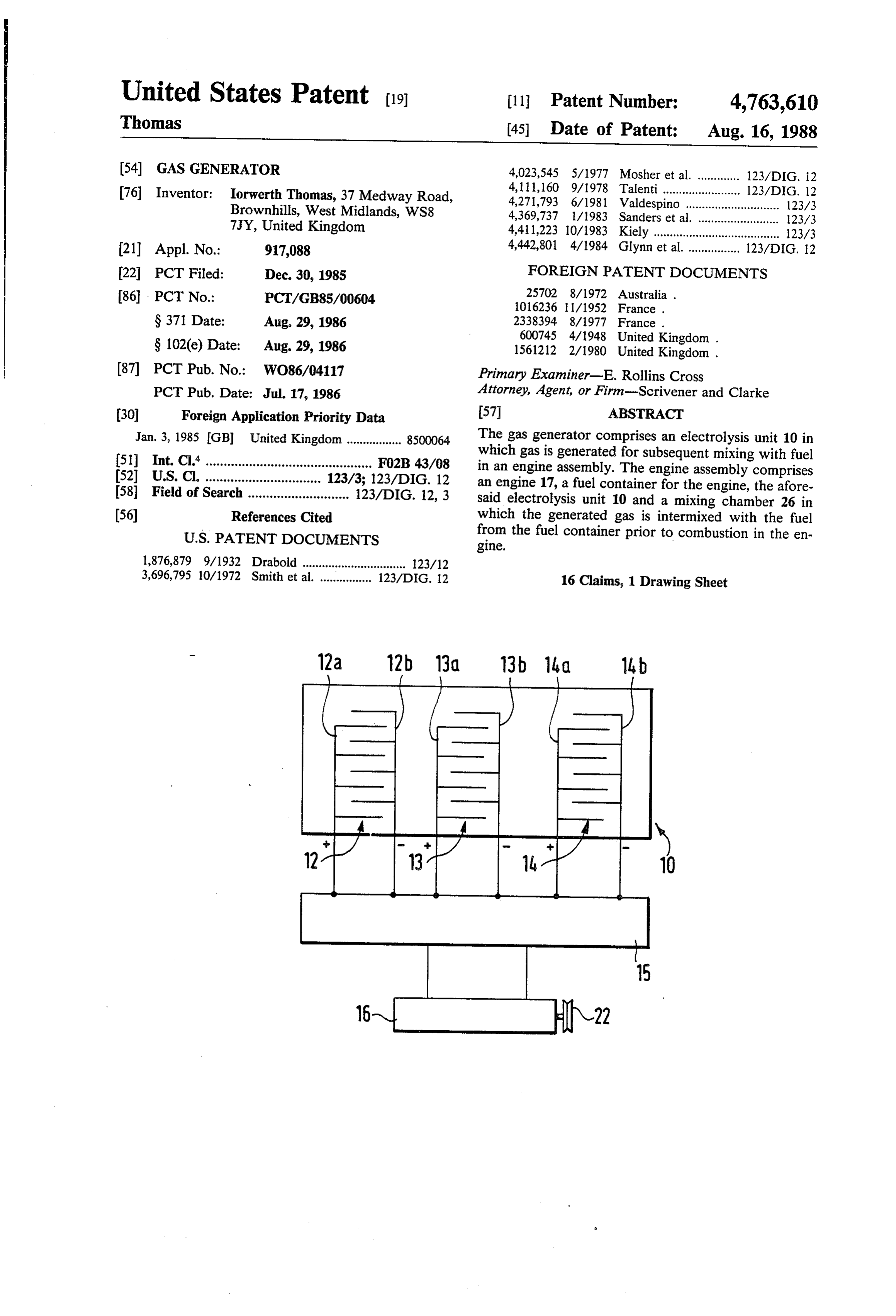
- 12a 12b 13 13b lid 14b
Page 2
Drawing sheet — no readable text.
Page 3
be fed to the fuel system, e.g. a carburetor, through
GAS GENERATOR non-return means such as a water valve.
Where the unit is mounted in a vehicle, the electrical
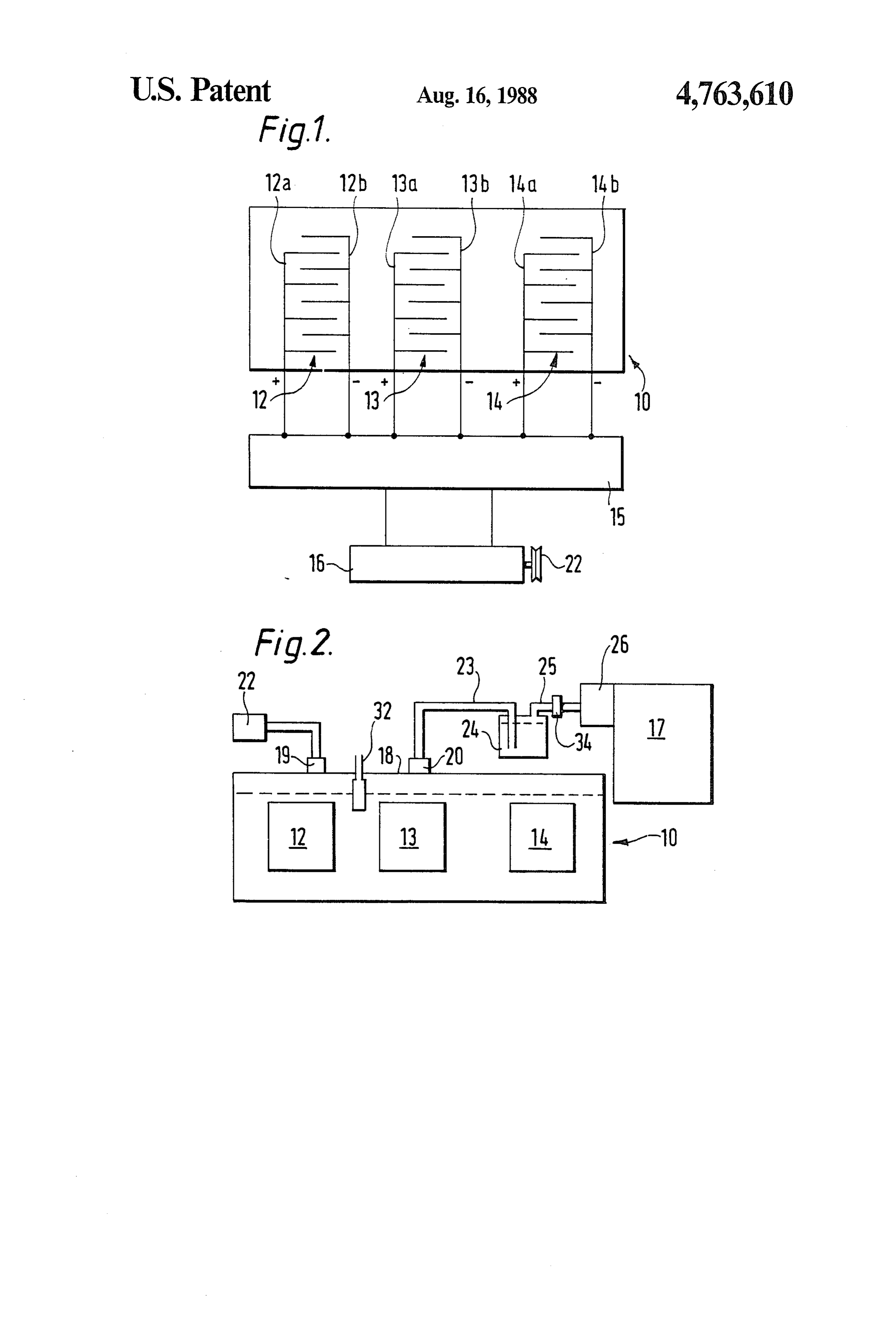
This invention relates to a gas generator and in partic current may be derived from an alternator driven by the ular to an electrolysis unit which is particularly, but not engine. Current derived from the alternator is prefera exclusively, for converting water into hydrogen and bly rectified to produce the electrical current necessary oxygen for use in conjunction with hydrocarbon fuel in for powering the electrolysis unit. prime movers, stationary engines, ships, furnaces, An electrolysis unit in accordance with the invention power stations and other applications. The invention will now be described by way of example with refer further relates to an engine assembly utilising the gas 10 ence to the accompanying drawings in which: generator. FIG. 1 is a plan view of a typical electrolysis unit in It has been proposed hitherto to utilise hydrogen gas accordance with the invention showing electrical con in conjunction with petrol in internal combustion en nections, and gines as a petrol-saving measure. Typically, this has FIG. 2 is an elevation of the unit of FIG. 1 showing been carried out by producing the gas in relatively small 15 diagrammatically the connection of the unit to a fuel quantities and storing the gas in a suitable container system of an internal combustion engine. from which it is fed to the engine. However, hydrogen Tank 10 contains three sets of electrodes indicated gas stored in that way is dangerous and an object of the generally at 12, 13 and 14 corresponding respectively to present invention is to provide an electrolysis unit the aforesaid first, second and third sets of electrodes. which will enable gas, typically hydrogen gas, to be 20 The first set 12 comprises a bank of anode electrodes produced in relatively large quantities thereby avoiding 12a and a bank of cathode electrodes 12b. The electrode the need to use a storage tank for the gas in the vehicle. sets 13 and 14 comprise respective anode and cathode According to one feature of the invention I provide sets 13a, 13b and 14a, 14b. The respective electrode sets an engine assembly comprising an engine, a fuel con 25 are connected to a rectifier unit 15 which receives elec tainer for the engine, an electrolysis unit, an electrical trical current from an alternator 16 driven by the inter supply for the electrolysis unit, and a mixing chamber in nal combustion engine 17 of a vehicle. The alternator is which gas generated by the electrolysis unit can be preferably of the kind set out in my co-pending British intermixed with fuel from the fuel container prior to Application rent output
No. 2120865A which provides a high-cur at low voltage.
combustion in the engine.
According to a further feature of the invention there 30 The sets of electrodes 12, 13 and 14 are immersed in is provided an electrolysis unit comprising a container, an electrolyte in the tank 10 which may be a solution an electrolyte in the container and first and second sets comprising proportions 30% sodium hydroxide to 70% water. The can vary as desired.
of electrodes immersed in the electrolyte which receive electrical current. In use the electrical potential across 35 inlet 19 and anprovided
The tank is with a lid 18 which includes an outlet 20. Solution is fed to the inlet from the first set of electrodes may be different from the a reserve tank 22 to maintain a constant level 21 of electrical potential across the second set of electrodes, solution in the tank during electrolysis. Gas produced and the different sets of electrodes may be brought into by electrolysis, typically hydrogen and oxygen, leaves operation successively or in combination to provide the outlet 20 and passes through a conduit 23 having an extra gas output as engine speed rises. At least part of 40 outlet end positioned beneath the surface of water in a the oxygen is used to convert the pollutants produced in water valve 24. A pipe 25 has an inlet end located above the cylinder from the combustion of the hydrocarbon the surface of fuel i.e. nitrous oxides and carbon monoxide, into non end terminatingtheat water in valve 24 and has an outlet polluting oxides, and if this chemical combination oc buretor 26 for the engine. The or an air filter an air intake of a car curs in an engine cylinder not only is the exhaust pollu 45 to the usual fuel supply for the engine. is connected carburetor tion reduced, but extra power is created in the cylinder. Once the engine is running, the alternator produces There may also be re-combination of hydrogen and current oxygen in the combustion chamber, also to produce e.g. 3 towhich is rectified and then fed at potentials of, power. To avoid the water produced by this re-combi and 14. If desiredto the 4 volts, the respective electrode sets 12, 13 potentials may be different for nation from inhibiting sparking, as a further feature of 50 each set of electrodes. The electrodes may be of stain my invention I provide spark electrodes disposed to be less steel. The spacing between adjacent electrodes of self-freeing of water, i.e. generally horizontally or sub each set may be around 3/16 (4.76 mm). stantially-horizontally such that the water formed drops The use of an electrolysis unit as described is particu fee or vibrates free to fall away. larly advantageous because it enables sufficient gas to It has been found that an electrolysis unit in accor 55 be produced to avoid the use of an intermediate storage dance with the invention is particularly efficient and, by reservior between the electrolysis unit and the carburet using a suitable electrical potential, e.g. provided by a ter. The use of a single electrolyte common to all the rectified current derived from an alternator of the kind electrodes makes available more ions for the electrolysis described in my co-pending application No. 2120865A, unit as a whole than would be the case if the electrodes will provide sufficient gas to meet engine demand 60 were immersed in respective individual containers of thereby avoiding the need to use an intermediate stor electrolytes. The use of the water valve prevents any age reservoir. risk of explosion travelling through pipe 23 from the Preferably, a third set of electrodes is provided in the engine.
container and is immersed in the electrolyte. The tank may be made of material such as plastics and Preferably, the unit is mounted in a motor vehicle and 65 can be as small as 6' (152 mm) wide, 5'' (127mm) deep is connected to a fuel system whereby the gas, in use, is and 8' (203 mm) long.
introduced into the fuel system for introduction into an The electrolysis unit produces gas only while the iternal combustion engine. In such a case, the gas may engine drives the alternator which is another advantage
Page 4
over the gas-storage system where large quantities of 7. An electrolysis unit for use in the assembly as gas may still be stored after the engine has been claimed in claim 1 comprising a container, an electro switched off. lyte in the container, first and second sets of electrodes The hydrogen and oxygen produced by the unit and immersed in the electrolyte, and means to supply the fed to the engine produces a reduction in pollutant 5 electrodes with electric current.
by-products of combustion. A typical exhaust emission bustion 8. A method of fueling an engine driven by the com analysis is set out below. of hydrocarbon fuel comprising storing hydro carbon fuel in a storage space adjacent the engine, pro viding an electrolysis unit including an electrolyte, said
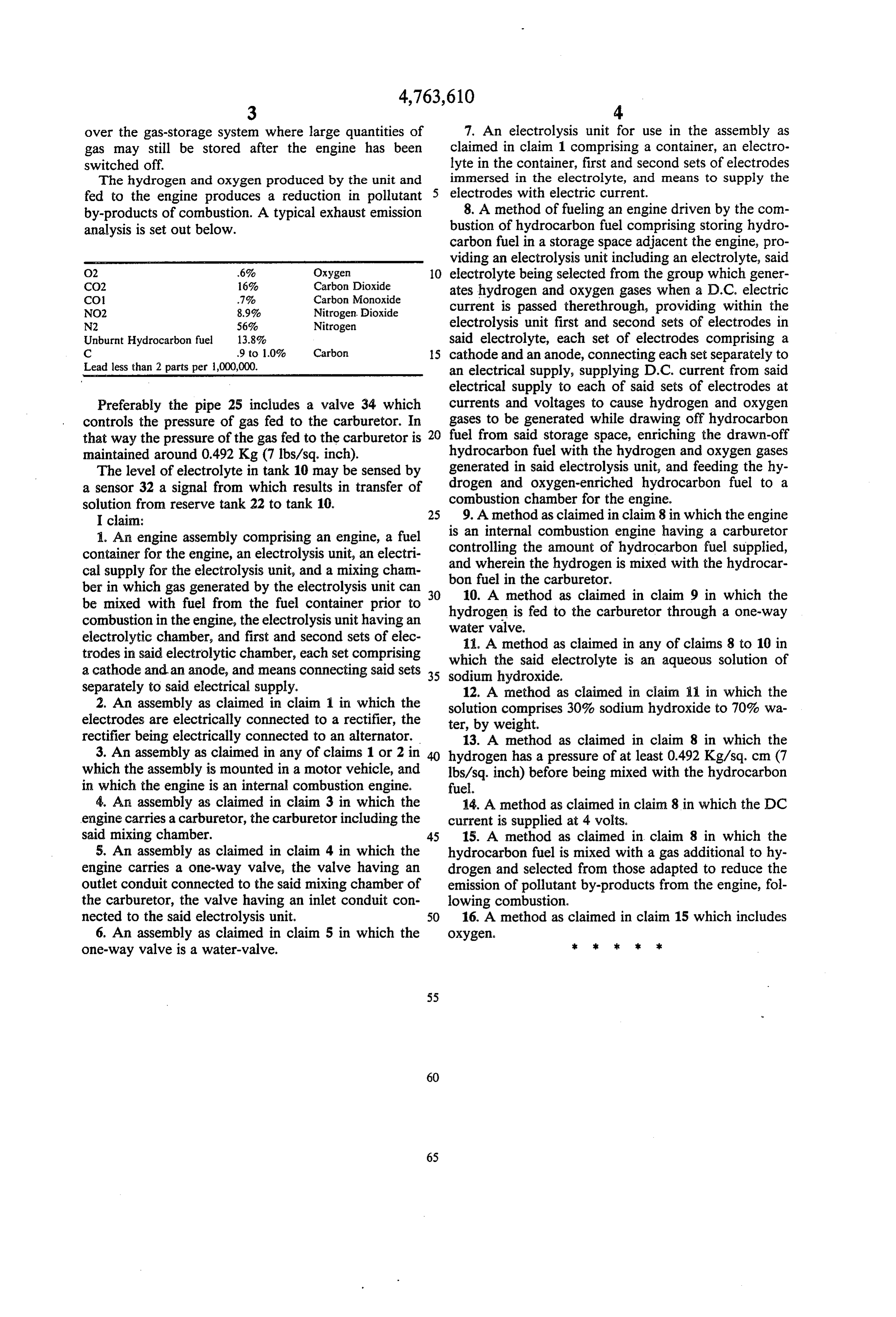
O2 .6% Oxygen O electrolyte being selected from the group which gener CO2 16% Carbon Dioxide ates hydrogen and oxygen gases when a D.C. electric
NO2 8.9% Nitrogen. Dioxide current is passed therethrough, providing within the N2 56% Nitrogen electrolysis unit first and second sets of electrodes in Unburnt Hydrocarbon fuel 13.8% said electrolyte, each set of electrodes comprising a C 9 to 1.0% Carbon 5 cathode and an anode, connecting each set separately to Lead less than 2 parts per 1,000,000. an electrical supply, supplying D.C. current from said electrical supply to each of said sets of electrodes at
Preferably the pipe 25 includes a valve 34 which currents and voltages to cause hydrogen and oxygen controls the pressure of gas fed to the carburetor. In gases to be generated while drawing off hydrocarbon that way the pressure of the gas fed to the carburetor is fuel from said storage space, enriching the drawn-off maintained around 0.492. Kg (7 lbs./sq. inch). hydrocarbon fuel with the hydrogen and oxygen gases The level of electrolyte in tank 10 may be sensed by generated in said electrolysis unit, and feeding the hy a sensor 32 a signal from which results in transfer of drogen and oxygen-enriched hydrocarbon fuel to a solution from reserve tank 22 to tank 10. combustion chamber for the engine. I claim: 25 9. A method as claimed in claim 8 in which the engine 1. An engine assembly comprising an engine, a fuel iscontrollingan internal combustion engine having a carburetor container for the engine, an electrolysis unit, an electri and whereinthe the amount of hydrocarbon fuel supplied, hydrogen is mixed with the hydrocar cal supply for the electrolysis unit, and a mixing cham bon fuel in the carburetor.
ber in which gas generated by the electrolysis unit can 30 10. A method as claimed in claim 9 in which the be mixed with fuel from the fuel container prior to hydrogen is fed to the carburetor through a one-way combustion in the engine, the electrolysis unit having an water valve.
electrolytic chamber, and first and second sets of elec 11. A method as claimed in any of claims 8 to 10 in trodes in said electrolytic chamber, each set comprising which a cathode and an anode, and means connecting said sets 35 sodium the said electrolyte is an aqueous solution of hydroxide.
separately to said electrical supply. 12. A method as claimed in claim 11 in which the 2. An assembly as claimed in claim 1 in which the solution comprises 30% sodium hydroxide to 70% wa electrodes are electrically connected to a rectifier, the ter, by weight.
rectifier being electrically connected to an alternator. 13. A method as claimed in claim 8 in which the 3. An assembly as claimed in any of claims 1 or 2 in 40 hydrogen has a pressure of at least 0.492. Kg/sq. cm (7 which the assembly is mounted in a motor vehicle, and lbs./sq. inch) before being mixed with the hydrocarbon in which the engine is an internal combustion engine. fuel.
4. An assembly as claimed in claim 3 in which the 14. A method as claimed in claim 8 in which the DC engine carries a carburetor, the carburetor including the current is supplied at 4 volts.
said mixing chamber. 45 15. A method as claimed in claim 8 in which the 5. An assembly as claimed in claim 4 in which the hydrocarbon fuel is mixed with a gas additional to hy engine carries a one-way valve, the valve having an drogen and selected from those adapted to reduce the outlet conduit connected to the said mixing chamber of emission of pollutant by-products from the engine, foll the carburetor, the valve having an inlet conduit con lowing combustion.
nected to the said electrolysis unit. 50 16. A method as claimed in claim 15 which includes 6. An assembly as claimed in claim 5 in which the OXygen.
one-way valve is a water-valve.
Provenance
- Collection
- Cited prior art
- Original PDF
- patentimages.storage.googleapis.com →
- Filed
- 1985-12-30
- Pages
- 4
- Method
- pdftotext (the PDF's own text layer) + pdftoppm 300dpi page scans
- Source
- Google Patents bibliographic record
- Granted
- 1988-08-16
- Inventors
- Iorwerth Thomas
- Transcribed from
- patentimages.storage.googleapis.com →