patent · US4369737
Hydrogen-oxygen generator
25 January 1983
Page 1 — bibliographic record
United States Patent (19) 11) 4,369,737 Sanders et al. 45 Jan. 25, 1983 54 HYDROGEN-OXYGENGENERATOR 4,023,545 5/1977 Mosher et al....................... 123/536
76 Inventors: Cledith A. Sanders; Margaret M.
Sanders; Cledith A. Sanders, II, all of Primary Examiner-Charles J. Myhre 7391 Wending Ct., S., Jacksonville, Assistant Examiner-E. Rollins Cross
Fla. 32210 Attorney, Agent, or Firm-Arthur G. Yeager 21 Appl. No.: 155,788 57 ABSTRACT (22) Filed: Jun. 2, 1980 A cell for generating hydrogen and oxygen comprised (51) Int. Cl. ...... a w w a 8 d 4 0 & 8 w8 g o we v in F02B 43/08 of a plastic housing and a plurality of regularly spaced (52) U.S. C. ....................................... 123/3; 123/1 A; metallic electrode rods positioned substantially parallel 123/DIG. 12; 204/129; 204/278 to the bottom of the housing; an aqueous solution of (58) Field of Search .................. 123/1 A, 3, DIG. 12, sodium bi-sulfate in which the rods are immersed; half 123/536; 204/129, 278, 266 of the rods being positive and attached to a source of D.
(56) References Cited C. electricity and the other half of the rods being nega tive and attached to a ground connection; the rods,
2,384,463 9/1945 Gunn et al. ... 123/DIG. 12 is adjacent solely to negative rods and each negative 2,509,498 5/1950 ... 123/DIG. 12 rod is adjacent solely to positive rods. This cell finds
12/23 particular use as a fuel generator for internal combus
to engines.
3,980,053 9/1976 Horvath .................................. 123/3 12 Claims, 4 Drawing Figures
Page 2
Drawing sheet — no readable text.
Page 3
Drawing sheet — no readable text.
Page 4
HYDROGEN-OXYGEN GENERATOR DETAILED DESCRIPTION OF THE
INVENTION
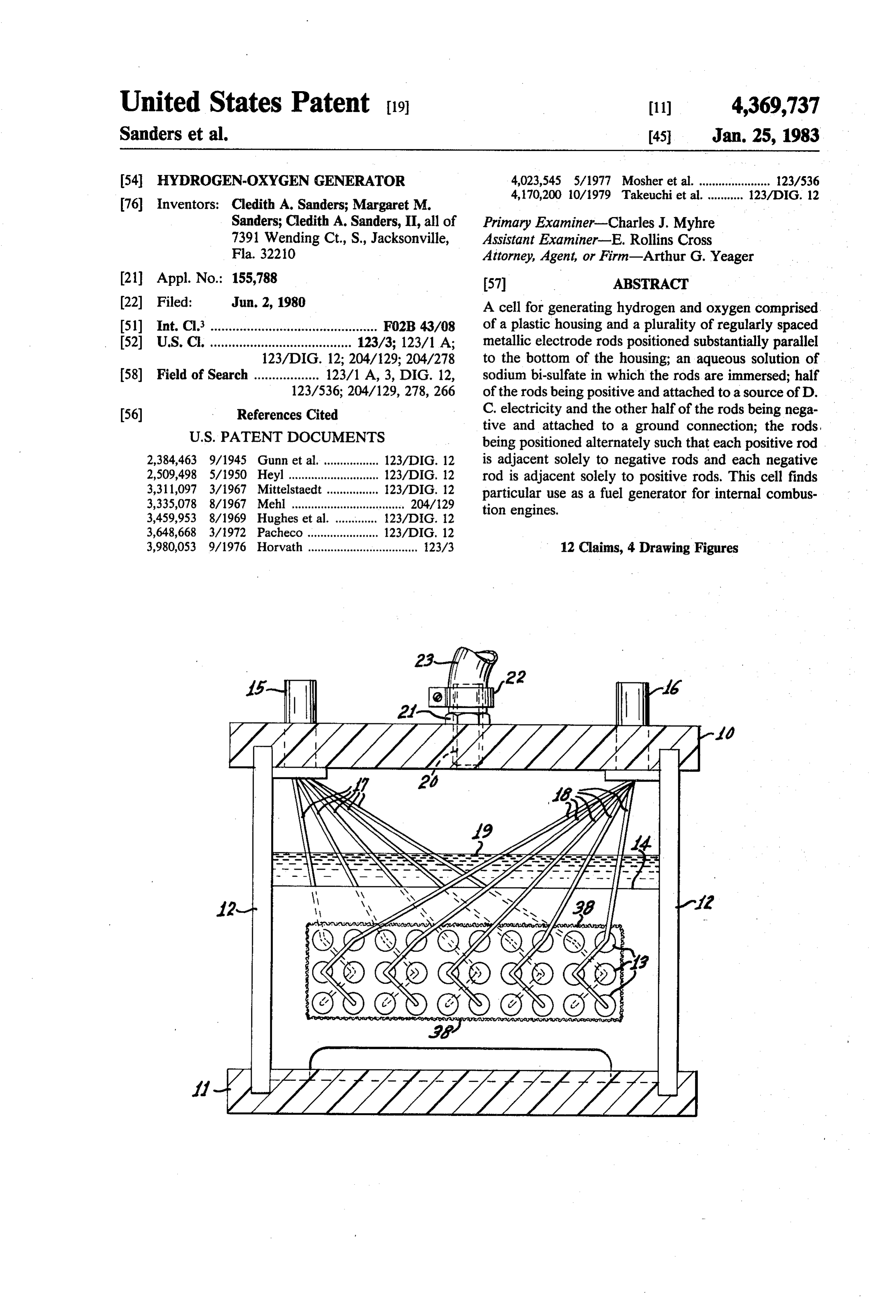
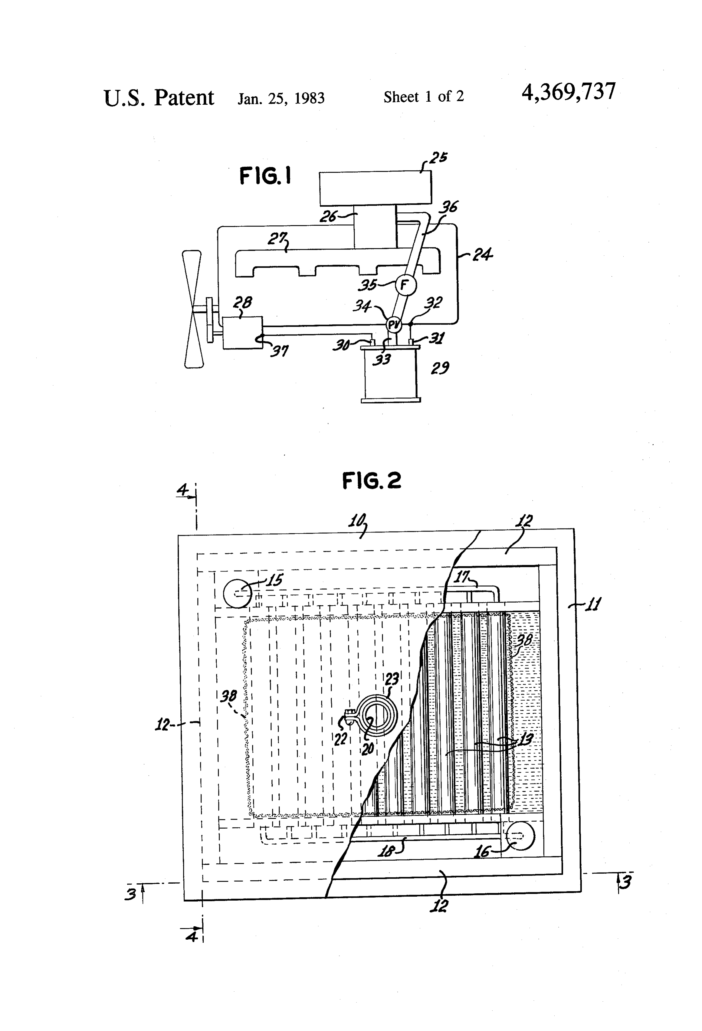
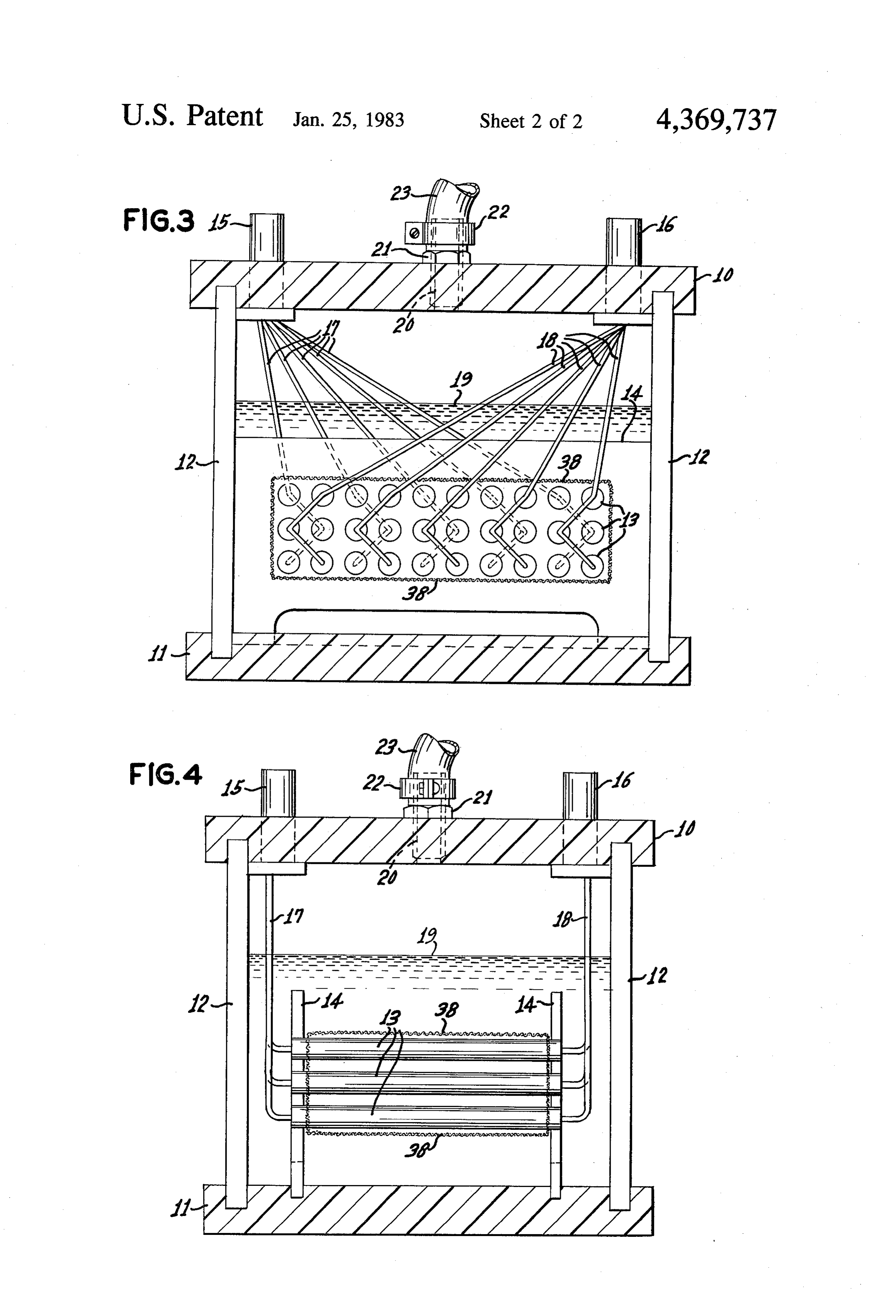
BACKGROUND OF THE INVENTION With specific reference to FIGS. 2, 3, and 4, the cell A considerable amount of research and development 5 of this invention may be best understood. In general, the has been directed at improvements for internal combus cell is a closed housing containing metallic electrode tion engines. In recent times an increasing amount of rods and a liquid electrolyte with the electrodes being connected to either of two terminal posts similar to an effort has been directed toward the development of fuel electric which is not totally derived from petroleum. One such storage battery employed in automobiles. The fuel which has received a small amount of attention in 0 cell of this invention is not, however, designed to store the past is hydrogen, but the cost of producing hydro electricity, but rather to use electricity in the produc tion of a mixture of hydrogen and oxygen gases by gen has been a major obstacle in pursuing this course of electrolysis action. There have been some attempts in this regard as cell. An exitofport the aqueous electrolyte solution in the is provided in the housing of the cell evidenced by the disclosures in the U.S. Pat. Nos. 15 to conduct the mixture of hydrogen and oxygen gases
the use of an electrolytic cell for making combustible away from the cell for whatever purposes these gases my serve. In a particular embodiment of this invention mixtures of hydrogen and oxygen from water, and using these gases will be conducted into the intake manifold this mixture of gases as fuel for the engine. For various of reasons the cells of these disclosures have not been 20 an internal combustion engine.
efficient and therefore have not been widely used in upper The housing of the cell of this invention comprises as engines in modern times. Nevertheless, this is a fruitful These wall 10, a lower wall 11, and four side walls 12. walls may be joined in any fashion suitable in the area for development work because of the large energy preparation of a liquid-tight and gas-tight housing. The potential in the burning of hydrogen which does not material of the housing may be any material which is produce air pollution. Accordingly, it is an object of 25 sufficiently strong and resistant to the corrosion pro this invention to provide an improved cell for generat duced by an electrolysis process. It is preferred that the ing hydrogen and oxygen mixtures that may be used as material of the housing be a suitable plastic because of the fuel for internal combustion engines. its low density and corrosion-resistance. Polyethylene is BRIEF SUMMARY OF THE INVENTION well suited for this purpose and is the preferred material 30 of construction. Such a plastic may be fabricated into
This invention provides a cell for generating hydro gen and oxygen which comprises a nonconductive the housing by a tongue-and-groove construction as shown in these drawings and made into a rigid structure housing; a plurality of regularly spaced electrode rods by a suitable parallel to the bottom of the housing; an aqueous elec heat welding.adhesive of the same plastic material or by Furthermore, since this material is rea trolyte solution, preferably sodium bi-sulfate, in suffi 35 sonably transparent, the condition of the interior parts cient amount to immerse all of said electrode rods; one of the cell may be readily seen.
half of said rods being positive and conductively at Inside of the housing is a plurality of metallic elec tached to a source of direct current electricity and the trode rods 13 arranged to produce the desired electroly other half of said rods being negative and conductively sis. The electrode rods 13 are placed in a plurality of attached to a ground; said rods being positioned such 40 layers parallel to lower wall 11 of the housing. In order that each positive electrode rod is adjacent solely to for the cell to function efficiently electrode rods 13 negative electrode rods and each negative electrode rod must be regularly spaced from each other in the same is adjacent solely to positive electrode rods. In a specific layer and from other electrode rods in adjacent layers.
embodiment of this invention the rods are lead and are This preferred arrangement of electrode rods 13 is ac positioned in a plurality of horizontal rows, each row 45 complished by means two parallel upright supports 14 being spaced vertically from an adjacent row. In a spe which have been machined with suitable holes in a cifically preferred embodiment the electrode rods are predetermined spaced pattern such that both ends of an approximately six inches long and are carried in a hous electrode rod 13 fit snugly into holes in supports 14. It ing of polyethylene in which the electrolyte is an aque is desirable to employ polyethylene for supports i4 ous solution of sodium bi-sulfate. 50 since this is an excellent insulating material. It is also BRIEF DESCRIPTION OF THE DRAWINGS preferable that electrode rods 13 be made of lead, rather The novel features believed to be characteristic of than a precious metal, since lead will not deteriorate over many years of use. It is preferable for rods 13 to be this invention are set forth with particularity in the in the form of cylinders.
appended claims. The invention itself, however, both as 55 Each electrode rod 3 is fitted at one end thereof with to its organization and method of operation, together an insulated electrically conductive wire 17 or 8 of with further objects and advantages thereof, may best sufficient length to be connected to an appropriate ter be understood by reference to the following description minal post 15 or 16 as maybe seen in FIG. 3. Half of the taken in connection with the accompanying drawings in electrodes 13 are connected to terminal post 15 and the which: 60 other half of electrodes 13 are connected to terminal FIG. is a schematic illustration of the cell of this post 16. In order for the electrolysis reaction to function invention employed as an accessory of an internal com properly a direct current must be imposed upon the bustion engine. electrode rods 13 such that half of them are positive and FIG. 2 is a top plan view of the cell of this invention.
the other half are negative. Thus terminal post 15 may
FIG. 3 is a front cross-sectional view taken along 65 be connected to a positive source of direct current and 3-3 of FIG. 2. terminal post 16 may be connected to a ground in order FIG. 4 is a side cross-sectional view taken along 4-4 to complete the circuit. Each electrode rod 13 con of FIG, 2. nected to terminal post 15 will then become a positive
Page 5
electrode and each electrode rod 13 connected to termi cell 29 reaches at least 0.5 psi. When that pressure is nal post 16 will become a negative electrode. It is im reached pressure valve 34 opens to permit the mixture portant that each positive electrode have only negative of gases to be fed into carburetor 26. It is also desirable electrodes adjacent to it, and similarly, each negative that in conduit 36 there be a filter 35 to remove any electrode have only positive electrodes adjacent to it. unwanted acidic vapors that might be corrosive to the Accordingly, it will be seen from FIG. 3 that electrodes engine. Filter 35 contains soda lime which is a mixture 13 are arranged alternately (positive-negative-positive of sodium hydroxide and calcium oxide. Although it is negative etc.). The arrangement of electrodes 13 in the not shown in FIG. 1 there may be included in the opera next layer is also in the same alternating pattern within tor's controls a means to reduce the input of petroleum that layer, and is so positioned that any given electrode 10 fuel to carburetor 26 as the output of hydrogen and 13 has the opposite sign (positive or negative) from that oxygen from cell 29 increases and reaches a maximum. of electrodes 13 on either side of it in the same layer and If cell 29 is sufficiently large with respect to the com from that of electrodes 13 immediately above and below bustion volume of engine 24 the output of cell 29 can it in different layers. This arrangement permits maxi provide the full fuel capacity for engine 24. The energy mum use of the surface of each electrode 13 to generate 15 needed to operate cell 29 may be provided by electric hydrogen and oxygen. generator or alternator 28 of engine 24. The positive The arrangement of electrode rods 13 is totally im terminal 30 of cell 29 is connected to output terminal 37 mersed in aqueous electrolyte solution. The level of this of generator of alternator 28, and the negative terminal solution is shown at 19 to be sufficient to cover all elec 31 of cell 29 is attached to a suitable ground connection trode rods 13 and to leave an adequate space above the 20 32 of engine 24.
electrolyte for the collection of the mixture of hydrogen The hydrogen and oxygen generator of this invention and oxygen which is generated in the cell. The direct finds its principal use in generating fuel for an internal current arrangement, as described above, causes the combustion engine as described above. There are other water in the electrolyte to be decomposed into a mix uses for the device of this invention, such as the produc ture of hydrogen and oxygen in the proportion of two 25 tion of fuel for cutting and welding torches, the produc volumes of hydrogen for each single volume of oxygen. tion of hydrogen and oxygen for use in laboratory ex It is well known that such a mixture can be burned to periments, etc.
produce water vapor. Although water can be used by This cell may be made in any of a variety of sizes. It itself for the electrolyte, it is preferred to dissolve a may be helpful to understand the size which can be small amount of a substance in the water to provide 30 employed in an ordinary four-cylinder automobile en better electrical conductivity. The most desirable of gine. For such a purpose electrode rods 13 may be such substances is sodium bi-sulfate and it is used as a inch in diameter and six inches long placed in three fully concentrated solution in distilled water. As water layers (ten rods in each layer) with the spacing between is decomposed by the production of hydrogen and oxy rods in the same layer and the spacing between rods in gen, water must be added to replace the loss, but the 35 adjacent layers being inch. If rod supports 14 are : sodium bi-sulfate is not used up in the process. inch in thickness, thus covering a total of inch of the In upper wall 10 there is located an outlet port 20 length of each rod 13, the total surface area of all 30 permit the gases produced in the cell to be conducted electrode rods 13 is 259 square inches. The exhaust of an away for other uses. In the illustration shown in these engine operating with this fuel is substantially all water drawings exit port 20 is fitted with coupling 21 which is 40 vapor which will not pollute the atmosphere and will screwed tightly into a threaded hole in wall 10. Flexible not produce the haze and smog found in major popula tubing 23 fits over upper the end of coupling 21 and is tion centers.
held in place with a suitable clamp 22. Any other type While the invention has been described with respect of exit port and arrangement to conduct the gases away to certain specific embodiments, it will be appreciated from that port is suitable so long as it will contain the 45 that many modifications and changes may be made by hydrogen and oxygen mixture under whatever pres those skilled in the art without departing from the spirit sures are involved. of the invention. It is intended, therefore, by the ap It has been found to be desirable for more efficient pended claims to cover all such modifications and production of hydrogen and oxygen to wrap the ar changes as fall within the true spirit and scope of the rangement of electrode rods 13 with a netting 38 of an SO invention.
insulating plastic. The openings in the netting may be What is claimed as new and what is desired to secure to inch in size. It appears that netting 38 enhances the by Letters Patent of the United States is: production of gas by collecting the small gas bubbles 1. A cell for generating hydrogen and oxygen which and causing them to coalesce into larger gas bubbles comprises a nonconductive gas-tight housing having a which rise quickly to the top of the electrolyte and 55 hydrogen and oxygen exit port adjacent the top of said escape from the electrolyte to be directed into exit port housing; a plurality of regularly spaced parallel elon 20. gated metallic electrode rods positioned substantially In FIG. 1 there is shown the principal use for the parallel to the bottom of said housing; means for sup generator of this invention as an accessory of an internal porting said electrode rods within said housing in a combustion engine. Engine 24 is fitted with carburetor plurality of horizontal rows with each of said rows 26 having an intake air filter 25. The fuel mixture leav being spaced vertically from each other and with their ing carburetor 26 passes into intake manifold 27 which ends being in spaced vertical planes; an aqueous electro distributes the fuel mixture to each of the cylinders lyte immersing all of said electrode rods; means for (four shown here) of the engine. interconnecting one half of said rods at their ends in one Cell 29 has conduit 36 joining outlet port 33 or cell 29 65 said plane to a source of direct current electricity to with carburetor 26. It is desirable that in conduit 36 render same positive and for interconnecting the other there be a pressure valve 34 which remains closed until half of said rods at their ends in the other said plane to the pressure of the hydrogen and oxygen generated in ground to render same negative; said rods being posi
Page 6
tioned such that each said positive electrode rod is adja at their ends in the other said plane to ground to render cent solely to said negative electrode rods and each said same negative; said rods being positioned such that each negative electrode rod is adjacent solely to said positive positive electrode rod is adjacent solely to said negative electrode rods. electrode rods and each negative electrode rod is adja 2. The cell of claim 1 wherein said electrode rods are cent solely to said positive electrode rods; said plurality lead. of electrode rods being encircled by at least one layer of 3. The cell of claim 1 wherein said plurality of elec nonconductive netting having openings of to inch trode rods is encircled by a nonconductive netting hav for collecting small gas bubbles being produced and ing openings of to inch for collecting small gas causing same to coalesce into larger gas bubbles which bubbles being produced and causing same to coalesce 10 quickly rise through and escape from said electrolyte; into larger gas bubbles which quickly rise through and and a conduit attached to said exit to conduct a mixture escape from said electrolyte. of hydrogen and oxygen gas from said cell to said car 4. The cell of claim 2 wherein said rods are approxi buretor.
mately 0.5 inch in diameter and each rod is spaced from 7. The accessory system of claim 6 which addition adjacent rods by a distance of to inch. 15 5. The cell of claim 1 wherein said aqueous electro said comprises ally carburetor in said conduit intermediate said cell and a filter for removing acidic materials lyte is an aqueous solution of sodium bi-sulfate. from said gaseous mixture of hydrogen and oxygen. 6. An accessory system to an internal combustion engine comprising a cell for generating hydrogen and comprise a mass ofsystem 8. The accessory of claim 7 wherein said filter oxygen gas to be burned in said engine after being intro said mixture of hydrogen andsoda
oxygen passes.
duced into the carburetor of the engine, said cell com prising a nonconductive gas-tight housing having a ally comprises a pressure valve in saidwhich 9. The accessory system of claim 7 addition conduit which hydrogen and oxygen exit port adjacent the top of said opens to permit the passage of said gaseous mixture of housing; a plurality of regularly spaced parallel metallic electrode rods positioned substantially parallel to the 25 hydrogen and oxygen to said carburetor when the pres bottom of said housing; means for supporting said elec sure of said gaseous mixture is at least 0.5 psi. trode rods within said housing in a plurality of horizon 10. The accessory system of claim 6 wherein said tal rows with each of said rows being spaced vertically aqueous electrolyte is a saturated solution of sodium from each other and with their ends being in spaced bi-sulfate in water.
vertical planes; an aqueous electrolyte immersing all of 30 11. The accessory system of claim 10 wherein said said electrode rods; means for interconnecting at their electrode rods are lead.
said ends in one said plane one half of said rods to a 12. The accessory system of claim 5 wherein said source of direct current electricity to render same posi electrode rods are lead. k k ck k tive and for interconnecting the other half of said rods
Provenance
- Collection
- Cited prior art
- Original PDF
- patentimages.storage.googleapis.com →
- Filed
- 1980-06-02
- Pages
- 6
- Method
- pdftotext (the PDF's own text layer) + pdftoppm 300dpi page scans
- Source
- Google Patents bibliographic record
- Granted
- 1983-01-25
- Inventors
- Cledith A. Sanders; Margaret M. Sanders; II Cledith A. Sanders
- Transcribed from
- patentimages.storage.googleapis.com →