patent · US5753383A
Hybrid self-contained heating and electrical power supply process incorporating a hydrogen fuel cell, a thermoelectric generator and a catalytic burner
19 May 1998
Page 1 — bibliographic record
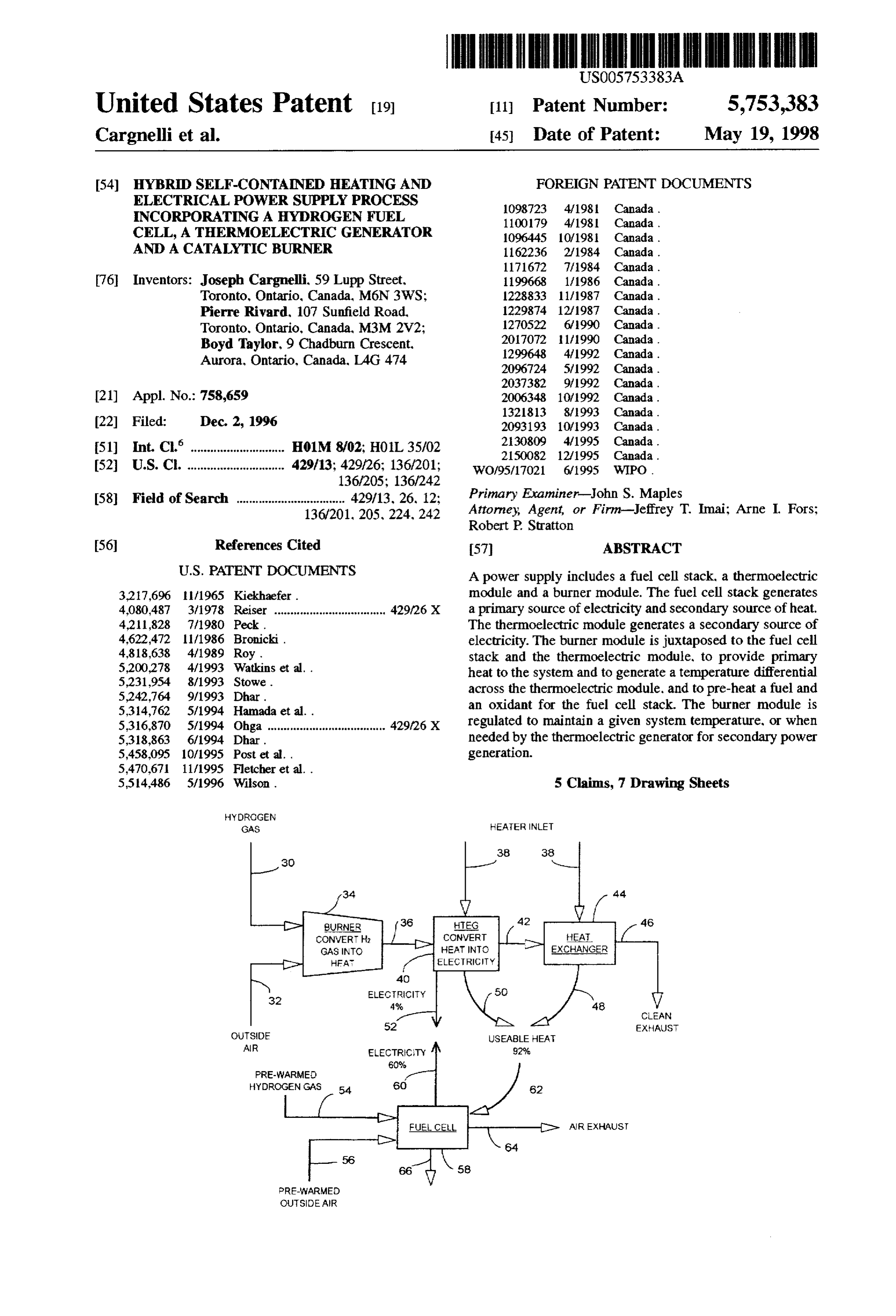
United States Patent (19) 11 Patent Number: 5,753,383 Cargnelli et al. 45) Date of Patent: May 19, 1998 54 HYBRID SELF-CONTAINED HEATING AND FOREIGN PATENT DOCUMENTS
ELECTRICAL POWER SUPPLY PROCESS
NCORPORATING A HYDROGEN FUEL 1982. As a CELL, A THERMOELECTRIC GENERATOR 1096445 10198 Canada.
AND A CATALYTC BURNER 1162236 2/1984 Canada.
76 Inventors: Joseph Cargnelli. 59 Lupp Street, 1996.68 1/1986 Canada. Toronto, Ontario, Canada, M6N 3WS: 1228833 11/1987 Canada.
Pierre Rivard, 107 Sunfield Road, 1229874 12f1987 Canada.
Toronto, Ontario, Canada, M3M 2V2; 270522 6,990 Canada.
Boyd Taylor, 9 Chadburn Crescent, f:3. y13: SG 3a.
Aurora, Ontario, Canada, LAG 474 2096724 5/1992 Canada.
(21) Appl. No.: 758,659 2006348 1/992 Canada.
22 Filed: Dec. 2, 1996 2093193 10/993 Canada. (51) Int. Cl. ......................... H01M. 8/02; HOL 35/02 230809 4/1995 Canada.
U.S. C. .............................. 429/3:s 429/26:4. 136/201: 2150O82 12/1995
58) Field of Search ................................. 429/13, 26, 12,
Primary Examiner-John S. Maples
Attorney, Agent, or Firm-Jeffrey T. Imai; Arne I. Fors;
Robert P. Stratton 56 References Cited 57 ABSTRACT
3.217,696 1/1965 Kiekhaefer. module and a burner module. The fuel cell stack generates 4.080,487 3/1978 Reiser ................................... 429/26 X a primary source of electricity and secondary source of heat. 4211,828 7/1980 Peck. The thermoelectric module generates a secondary source of 4,622,472 f1986 Bronicki. electricity. The burner module is juxtaposed to the fuel cell 4,818,638 4/1989 Roy stack and the thermoelectric module, to provide primary 2. s als et al. . heat to the system and to generate a temperature differential
towe.
acrossad the thermoelectric module, and to pre-heat a fuel and 5,314,762 5/1994 Hamada et al.. an oxidant for the fuel cell stack. The burner module is 5,316,870 5/1994 Ohga ..................................... 42926 x regulated to maintain a given system temperature, or when 5,318,863 6/1994 Dhar. needed by the thermoelectric generator for secondary power 5,458.095 10/1995 Post et al.. generation.
5,514.486 5/1996 Wilson. 5 Claims, 7 Drawing Sheets
YDRCGEN
GAS HEAERINET
TEG
ELECRCY
CEAN
OJTSOE 52 SEABLE HEA EX-AJS
AR EECTRICTY 92%
HYDROGENGAS 82
is AR EXHAUST
PRENARMD
OUSCEAR
Page 2
Drawing sheet — no readable text.
Page 3
Drawing sheet — no readable text.
Page 4
Drawing sheet — no readable text.
Page 5
Drawing sheet — no readable text.
Page 6
Drawing sheet — no readable text.
Page 7
Drawing sheet — no readable text.
Page 8
Drawing sheet — no readable text.
Page 9
HYBRD SELF-CONTA NED HEATING AND folds to the electrodes, while cooling is provided either by ELECTRICAL POWER SUPPLY PROCESS the reactants or by a cooling medium. Also within the stack ENCORPORATING A HYDROGEN FUEL are current collectors, cell-to-cell seals, insulation, piping, CELL, ATHERMOELECTRIC GENERATOR and instrumentation. The stack, housing, and associated AND A CATALYTC BURNER hardware make up the fuel cell module.
Fuel cells may be classified by the type of electrolyte.
FIELD OF THE INVENTION either liquid or solid. A fuel cell using a solid electrolyte, The present invention relates to hydrogen power sources such as a solid polymer referred to as a proton exchange of a type which receives hydrogen fuel and produces elec O will membrane is kept moist with water because the membrane tricity and heat. In particular, this invention relates to a requires not operate efficiently when dry. The membrane hybrid power supply which is particularly suited for sub constant humidification during the operation of the Zero temperature environments. fuel cell, normally by adding water to the reactant gases, usually hydrogen and oxygen. that pass by the membrane on
BACKGROUND OF INVENTION each side of the membrane?electrode assembly. 15 The proton exchange membrane used in a solid polymer
Thermoelectric generators, photovoltaics and primary fuel cell acts as the electrolyte as well as a barrier for batteries are used as a source of primary power in remote preventing the mixing of the reactant gases. An example of areas where the usual sources of power are inappropriate or a suitable membrane is a copolymeric perfluorocarbon mate unavailable, where service and maintenance of equipment is rial containing a basic unit of fluorinated carbon chain and limited, or where the transportation cost of the fuel is a major a sulphonic acid group. There may be variations in the component of the overall system's operating cost. Examples molecular configurations of this membrane. Excellent per of remote applications include: unattended communication formances are obtained using these membranes if the fuel repeaters, navigational aids, and weather and oceanographic cells are operated under fully hydrated, essentially water stations. For such applications, the power system must be saturated conditions and ambient temperatures. As such, the self-contained and highly reliable. Fuel cells however, 25 membrane must be continuously humidified. Further more, although used in large (larger than 250 KW) stationary the temperature of the fuel cell stack must be kept above applications and space are not commonly used in remote freezing in order to prevent freezing of the stack areas to date, because of their perceived lack of reliability Cooling, humidification and pressurization requirements and of their susceptibility to low temperatures when shut increase the cost and complexity of the fuel cell, reducing its down. 30 commercial appeal as an alternative energy supply in many Generally, a fuel cell is a device which converts the applications. Accordingly, advances in fuel cell research is energy of a chemical reaction into electricity. It differs from enabling fuel cells to operate without reactant conditioning, a battery in that the fuel cell can generate power as long as no flow-field provisions, and under air-breathing, atmo the fuel and oxidant are supplied. A fuel cell produces an spheric conditions while maintaining usable power output. electromotive force by bringing the fuel and oxidant into 35 The current state-of-the-art in fuel cells, although increas contact with two suitable electrodes and an electrolyte. A ingly focusing on simplified air-breathing atmospheric fuel, such as hydrogen gas, for example, is introduced at a designs, has not adequately addressed operations in sub-zero first electrode where it reacts electrochemically in the pres temperatures, which requires further complexity of the ence of the electrolyte to produce electrons and cations in the design. For instance, heat exchangers and thermal insulation first electrode. The electrons are circulated from the first are required, as are additional control protocols for startup, electrode to a second electrode through an electrical circuit shut-down, and reactant humidifiers.
connected between the electrodes. Cations pass through the A catalytic burner operates on a principle similar to fuel electrolyte to the second electrode. Simultaneously, an cells, but at an accelerated kinetic rate and increased tem oxidant, such as oxygen gas or air, is introduced to the perature. A fuel. for example hydrogen. is oxidized through second electrode where the oxidant reacts electrochemically 45 direct contact with oxygen or air at a rate induced by the in presence of the electrolyte consuming the electrons cir presence of a catalytic bed separating the two reactants, for culated through the electrical circuit and the cations at the example, ceramic beads containing small amount of plati second electrode. The anions formed at the cathode react num on the surface.
with the cations to forma reaction product. The first elec The by-product of the chemical reaction is similar to that trode may alternatively be referred to as an oxidizing or fuel 50 of a fuel cell:
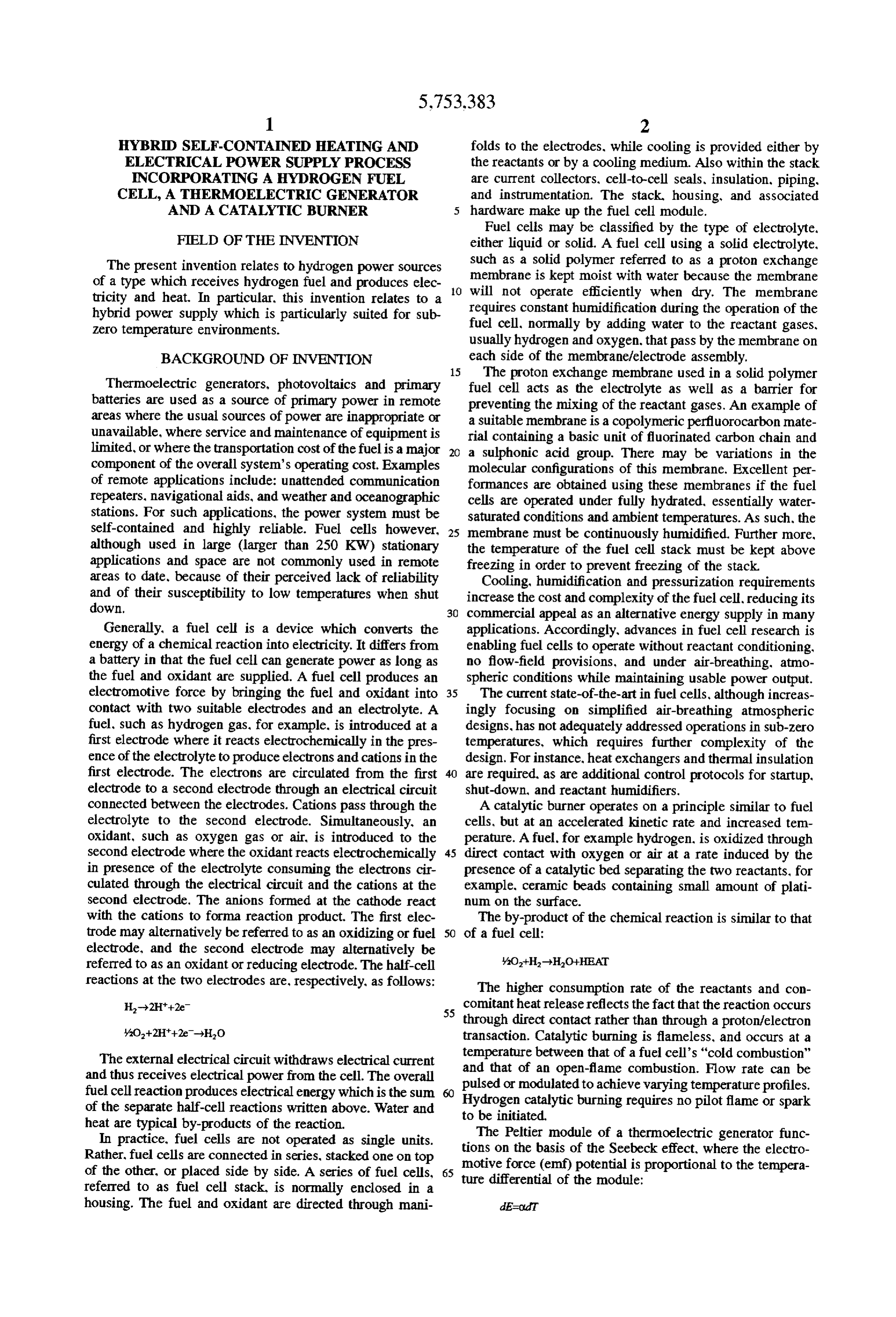
electrode, and the second electrode may alternatively be referred to as an oxidant or reducing electrode. The half-cell AO-H-HO+HEAT reactions at the two electrodes are, respectively, as follows: The higher consumption rate of the reactants and con comitant heat release reflects the fact that the reaction occurs
through direct contact rather than through a proton/electron transaction. Catalytic burning is flameless, and occurs at a
The external electrical circuit withdraws electrical current temperature between that of a fuel cell's "cold combustion" and thus receives electrical power from the cell. The overall and that of an open-flame combustion. Flow rate can be fuel cell reaction produces electrical energy which is the sum pulsed Hydrogen or modulated to achieve varying temperature profiles.
catalytic burning requires no pilot flame or spark of the separate half-cell reactions written above. Water and to be initiated.
heat are typical by-products of the reaction. The Peltier module of a thermoelectric generator func In practice, fuel cells are not operated as single units.
Rather, fuel cells are connected in series, stacked one on top tions motive on the basis of the Seebeck effect, where the electro force (emf) potential is proportional to the tempera of the other, or placed side by side. A series of fuel cells, ture differential
of the module:
referred to as fuel cell stack, is normally enclosed in a housing. The fuel and oxidant are directed through mani Ecold
Page 10
One thermoelectric element commonly used is a solid the temperature of the hot side of a thermoelectric element, state device manufactured by MELCOR. a thermoelectric generator to generate electricity, and a fuel A temperature differential between the hot catalytic cell to generate electricity and heat.
burner and the cool sub-zero air or cooling fins side of a According to another aspect of the invention, the fuel thermoelectric element generates a low-potential current supplied to the burner is intermittently supplied by regulat which can be used to service a load. ing a solenoid or proportionating valve responsive to a In generating electricity, fuel cells and thermoelectric temperature measurement at the central core of the fuel cell generators each possess comparative advantages and disad vantages. For instance, compared to fuel cells, thermoelec stack or at another strategic location in the system. According to another aspect of the invention, the catalytic tric generators are electrically inefficient, converting less 10 than 4% of the chemical energy available from the fuel into burner is coupled to the hot side of a thermoelectric element electricity, exhausting to the environment most of the fuel's through a thermal mass, for instance, an aluminum plate. energy as unused heat. They also require a spark or ignition The cool side of the element is intimately bonded to cooling source to fire up when operated on fuels other than hydro fins or to other active/passive cooling device, to increase the gen. The thermoelectrics' very low efficiency, low power temperature differential across the element. output and considerable fuel cell requirements are particu 15 According to another aspect of the invention, the single larly detrimental to applications where the fuel must be thermoelectric element can be cascaded by a number of transported over long, inaccessible distances such as moun elements in series or in parallel to achieve a specified tain top or Arctic applications. On the other hand, thermo voltage or amperage rating.
electric generators are very reliable and economical, have no moving parts and are operable in cold climates because of 20 theAccording to another aspect of the invention, the fuel for fuel cell is brought dead-ended, i.e. non-circulating to the catalytic burners' heat producing characteristics.
Fuel cells. in contrast, suffer from pre-commercial the oxidizing electrodes, at constant near-ambient or atmo unreliability, limited longevity and an inability to start spheric pressure.
According to another aspect of the invention, there is spontaneously in deep sub-zero temperatures. Sub-zero tem provided a method of generating heat and electrical energy. peratures upon shut down can freeze a stack and cause 25 The method includes the steps of damage to the structural components and electrode compo nents. On the other hand, fuel cells offer significantly higher supplying a fuel to a burner for generating a temperature efficiency in converting the fuel's chemical energy to elec differential across a thermoelectric element thereby tricity converting between 40 to 60% compared to the generating a secondary source of electricity. thermoelectric's 4%. 30 heating a system's enclosure or micro-climate. Separately-used fuel cells. thermoelectric generators or pre-heating a fuel for consumption by a fuel cell stack, catalytic burners are commercially available. Prior art supplying the pre-heated fuel to a heated fuel cell stack examples, such as Hamada et al., U.S. Pat. No. 5.314.762. thereby generating a primary source of electricity and offers a combination of a catalytic burner with a fuel cell. secondary source of heat, both operating on hydrogen where the burner is used to 35 regulating the fuel supplied to the burner to maintain a set preheat the fuel cell. Still others such as Bromberg et al. temperature in the system's enclosure and at the hot WO95/17021. offer the combination of a plasmatron and a side of the thermoelectric element and in the fuel cell fuel cell. However, none disclose the combination of fuel stack.
cell, thermoelectric generator and catalytic burner, the com According to another aspect of the invention, there is bination of which offers unique advantages for off-grid provided an open-flame burner operating at a relatively high powering in extreme climates. heat release regime to increase the temperature of the hot SUMMARY OF THE INVENTION side of a thermoelectric element.
According to another aspect of the invention, the fuel and
The disadvantages of the prior art when applied to cold oxidant weather. off-grid power may be overcome by providing a 45 atmosphericfor the fuel cell can be brought under higher-than pressure. with the oxidant. either air or oxygen.
hybrid electrical power source which receives hydrogen fuel at a pressure higher than that of the fuel. and produces electricity and heat. According to yet another aspect of the invention, the It is desirable to provide electricity and heating sources thermoelectric element is electrically connected to the fuel providing a degree of mutual redundancy to one another. cell stack, so that the fuel cells' current can be applied to the allowing the self-contained system to operate in the cold and Peltier modules to create a temperature gradient or differ to achieve levels of reliability, fuel economy and operability ential across the element, and by reversing the direction of unachievable by the previous state of the art without sig the current fed from the fuel cells to the thermoelectric nificant complexity and capital cost increases. elements. the power source can provide some degree of According to one aspect of the invention, there is pro heating or cooling of surfaces as required by some applica vided a power supply which includes a fuel cell stack, a tions.
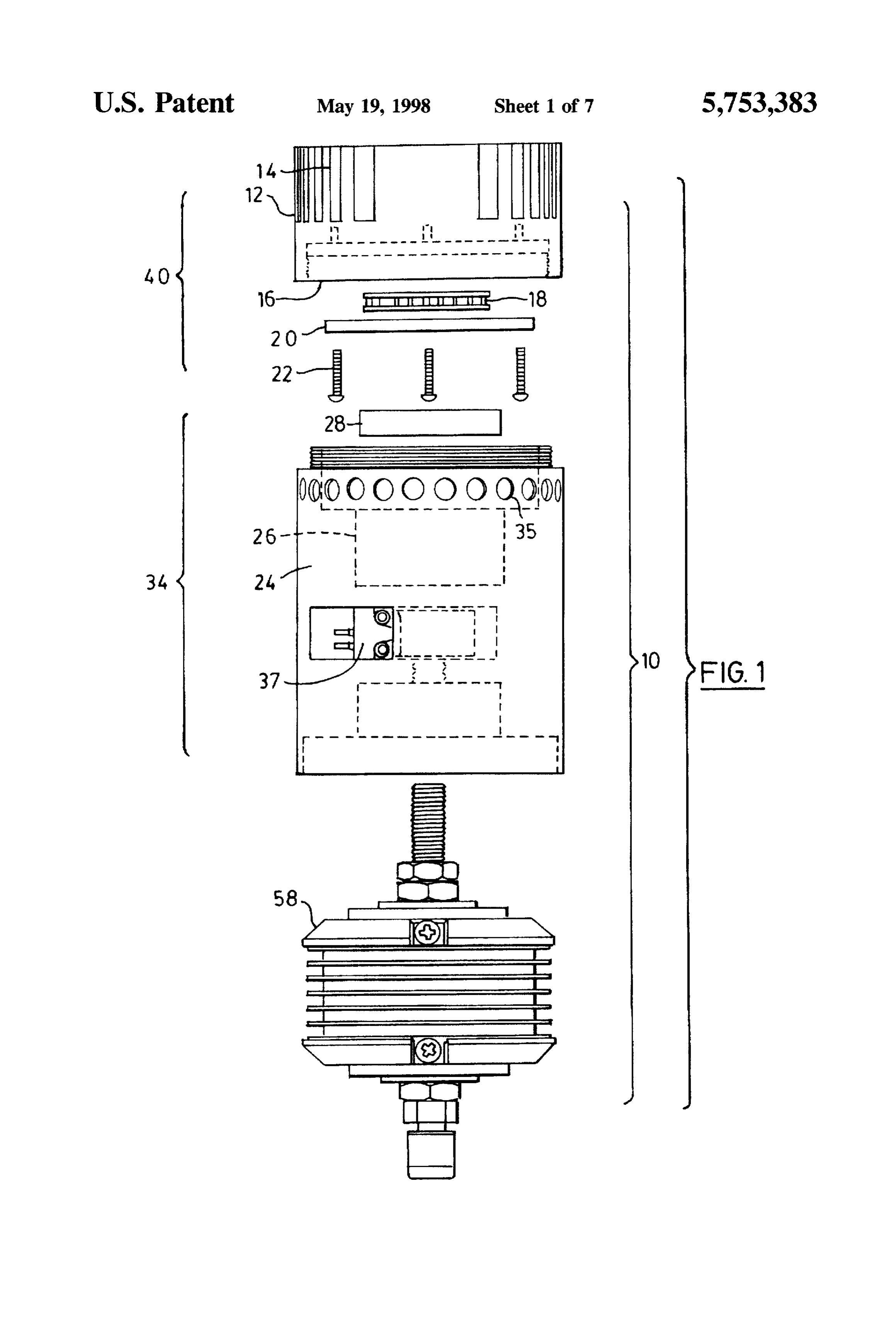
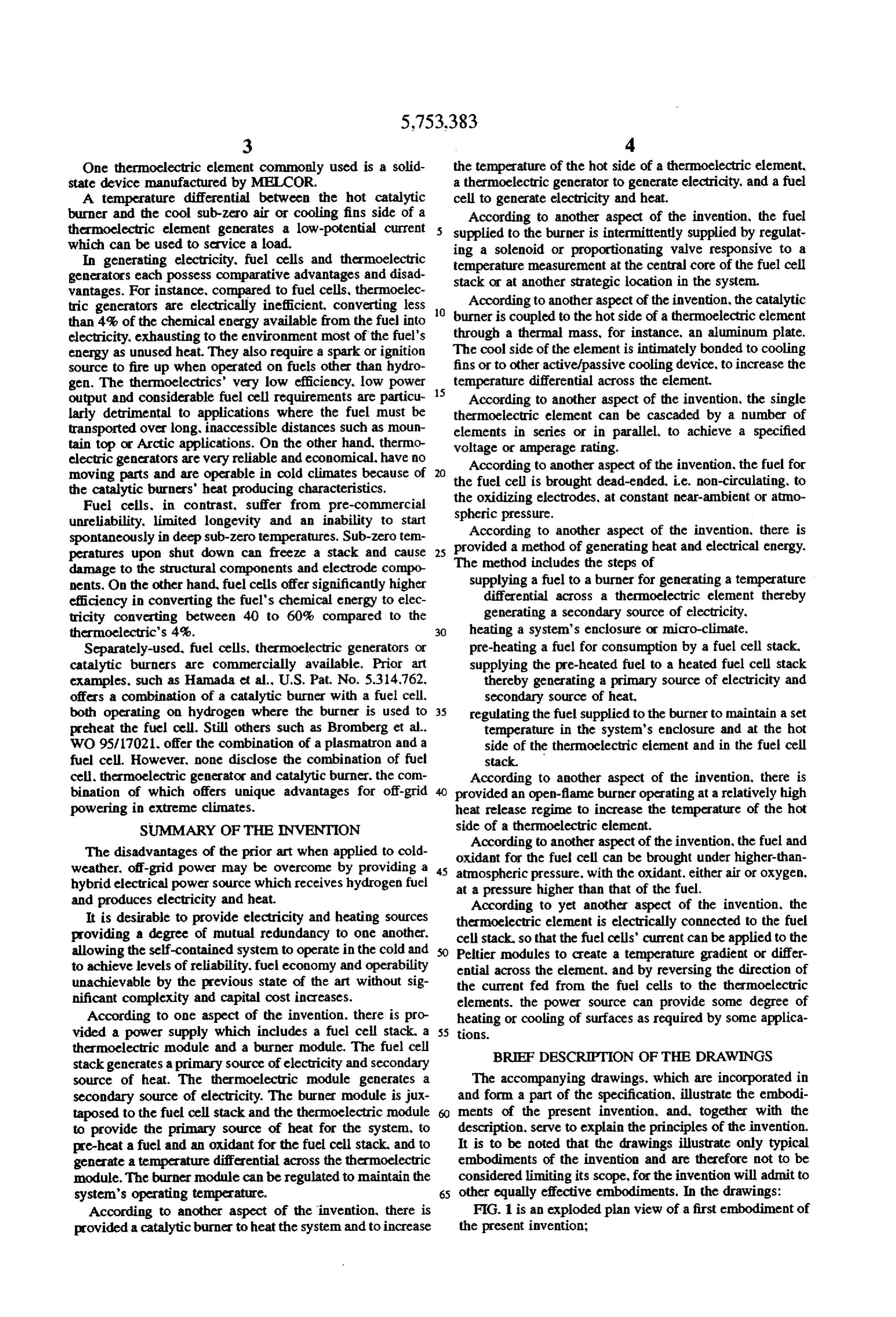
thermoelectric module and a burner module. The fuel cell stack generates a primary source of electricity and secondary BRIEF DESCRIPTION OF THE DRAWINGS source of heat. The thermoelectric module generates a The accompanying drawings, which are incorporated in secondary source of electricity. The burner module is jux and form a part of the specification, illustrate the embodi taposed to the fuel cell stack and the thermoelectric module ments of the present invention, and, together with the to provide the primary source of heat for the system, to description, serve to explain the principles of the invention. pre-heat a fuel and an oxidant for the fuel cell stack, and to It is to be noted that the drawings illustrate only typical generate a temperature differential across the thermoelectric embodiments of the invention and are therefore not to be module. The burner module can be regulated to maintain the considered limiting its scope, for the invention will admit to system's operating temperature. 65 other equally effective embodiments. In the drawings: According to another aspect of the invention, there is FIG. 1 is an exploded plan view of a first embodiment of provided a catalytic burner to heat the system and to increase the present invention;
Page 11
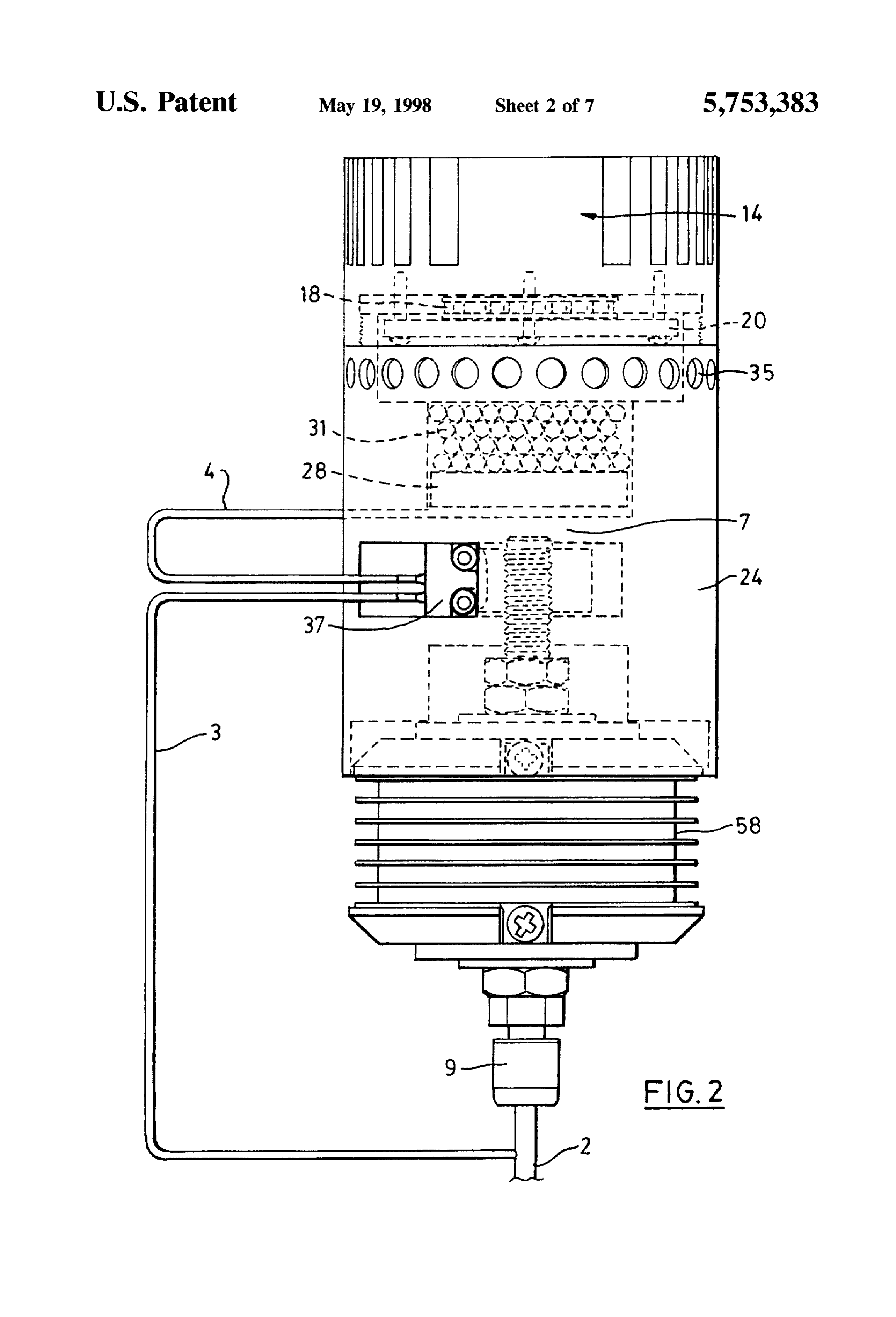
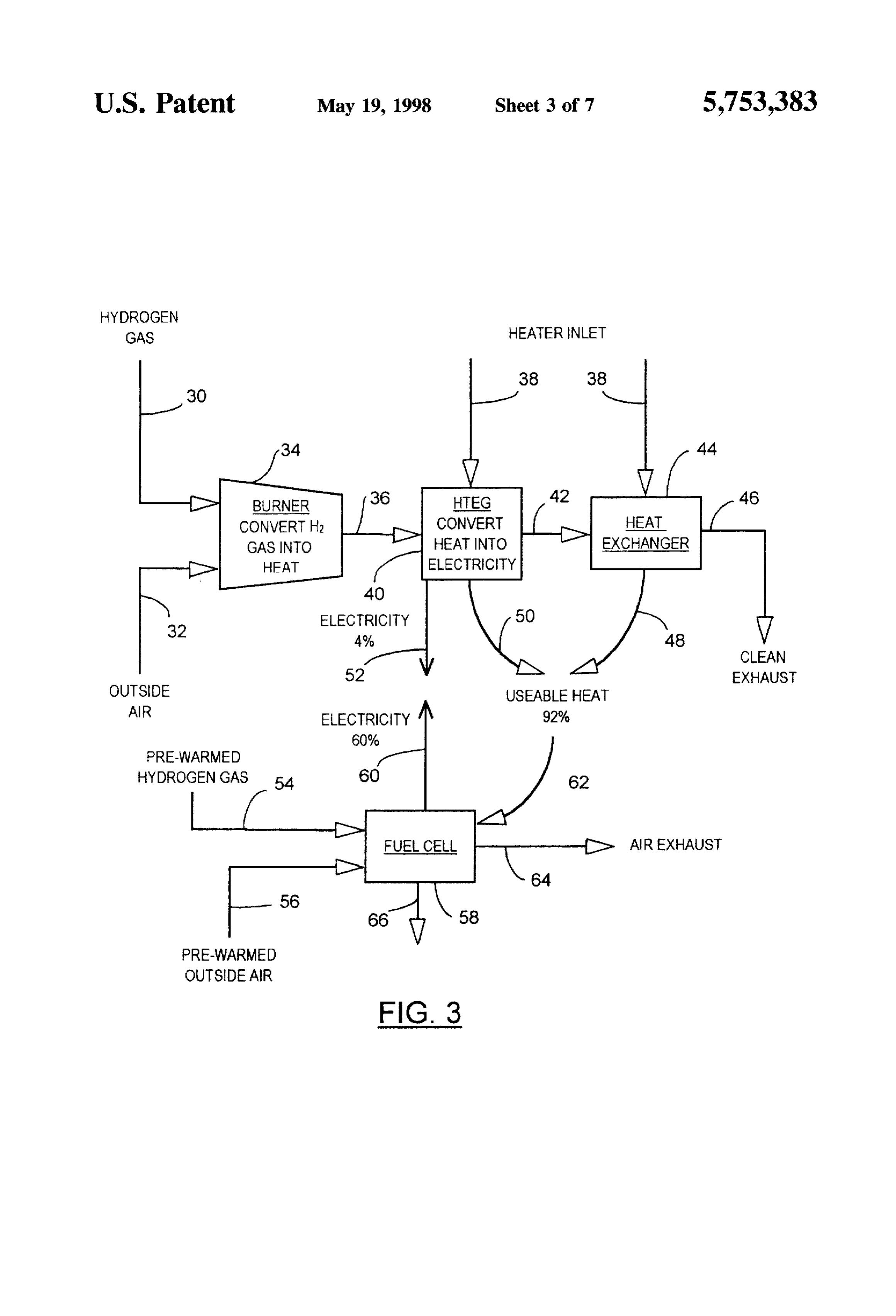
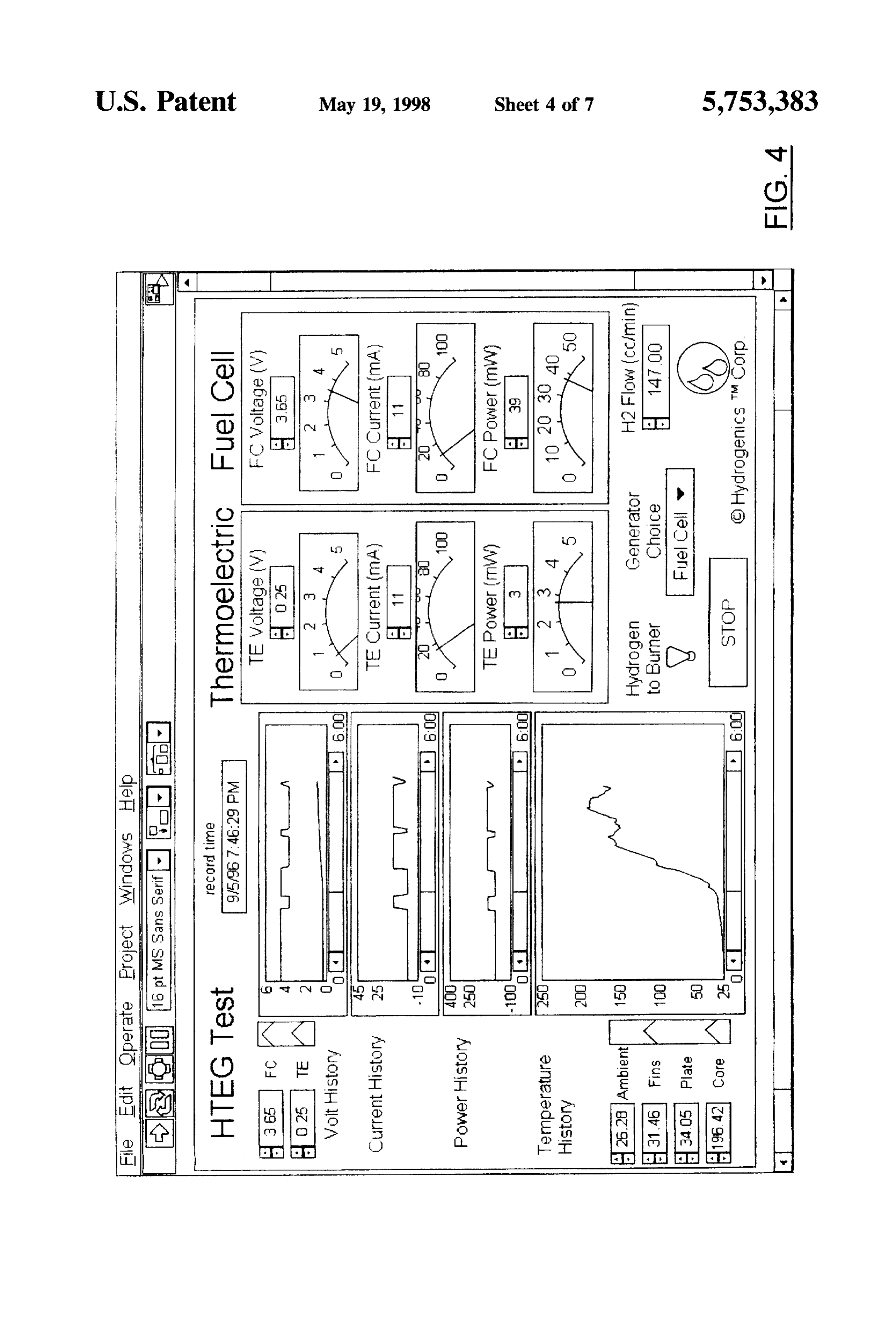
FIG. 2 is a plan view of an assembled system of the However, the advantage of this waste heat is that it can be embodiment of FIG. 1: utilized to warm the fuel cell stack 58 and peripherals and FIG. 3 is a schematic diagram of the electrical, heat and the electrical power 52 can be used to provide start-up power chemical transactions of the system of the embodiment of for parasitic peripherals or as emergency backup power. The FIG. 1; 5 processed (heated) fuel stream 54 along with the processed FIG. 4 is a computer display of the embodiment of FIG. (heated) oxidant stream 56 is fed into a fuel cell 58 which 1 illustrating typical graphs of the power source's various can convert more than 60% of the available energy into parameters; electricity 60. Some of the energy is wasted as heat 66 and some leaves via the exhaust vent 64.
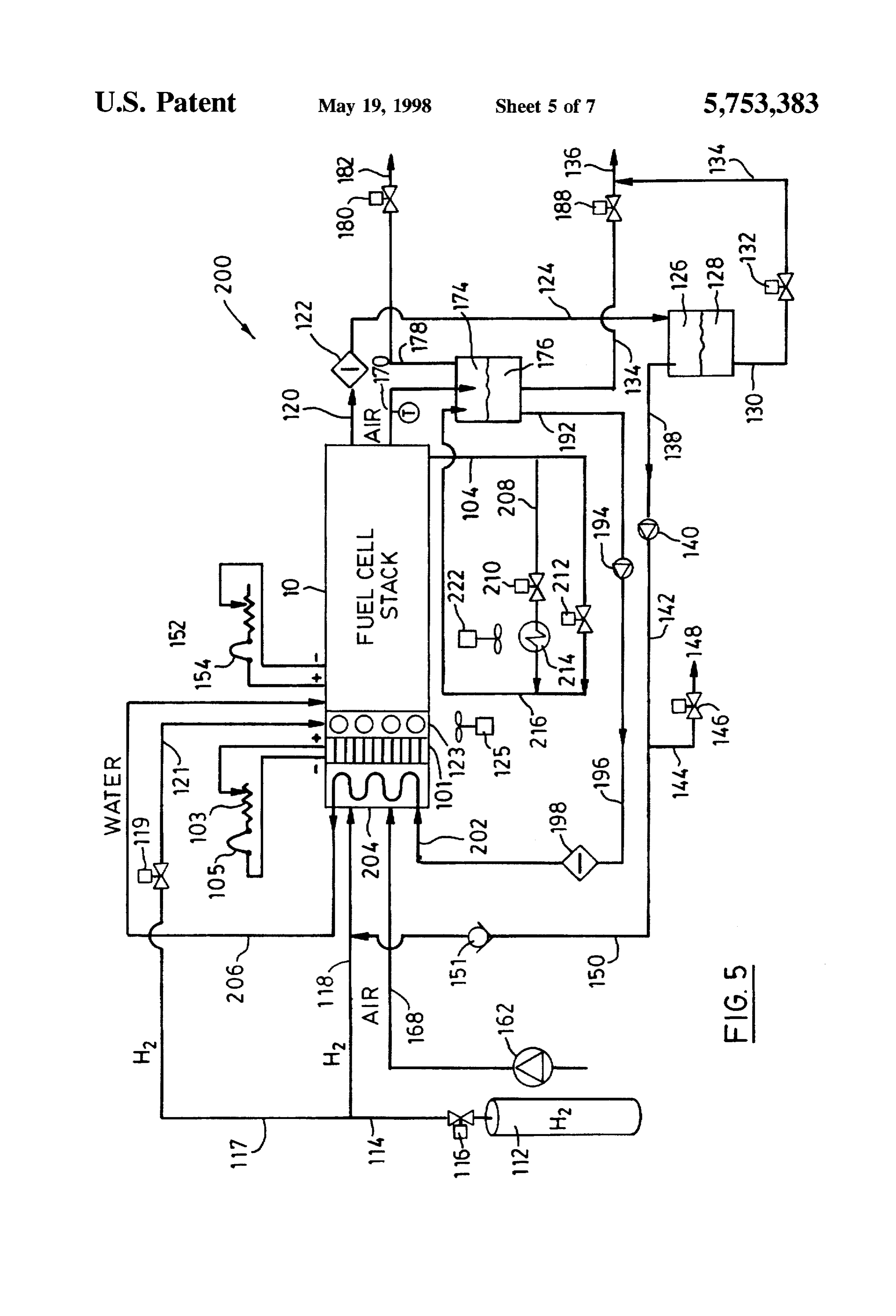
FIG. 5 is a schematic diagram of a second embodiment of 10 The display of FIG. 4 present the performance of the the present invention;
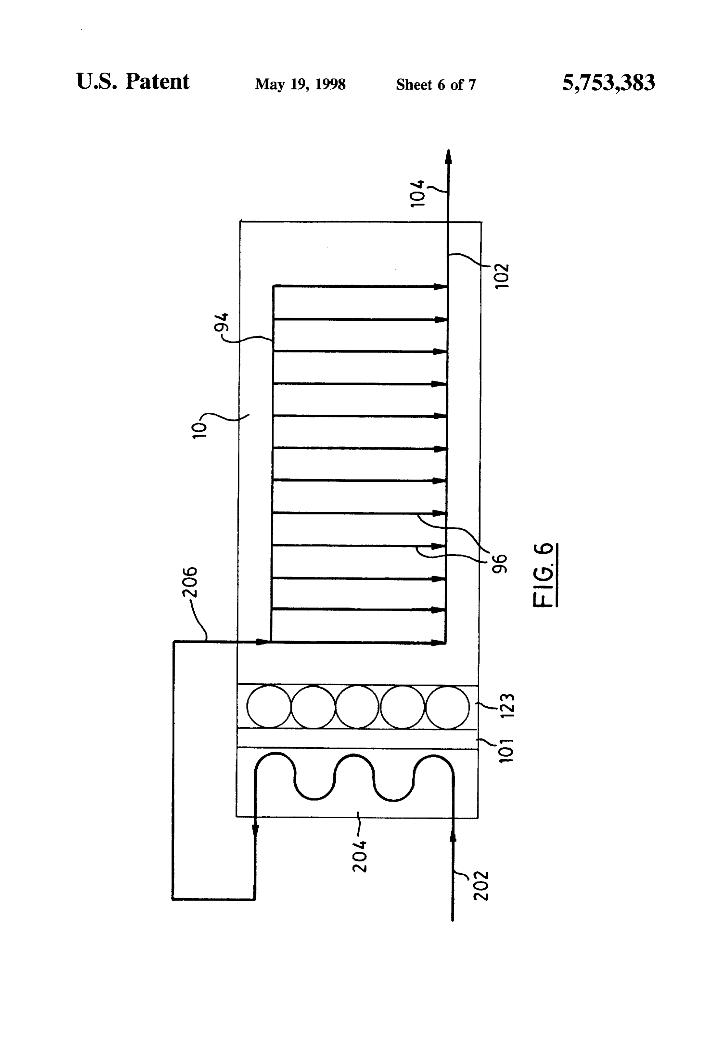
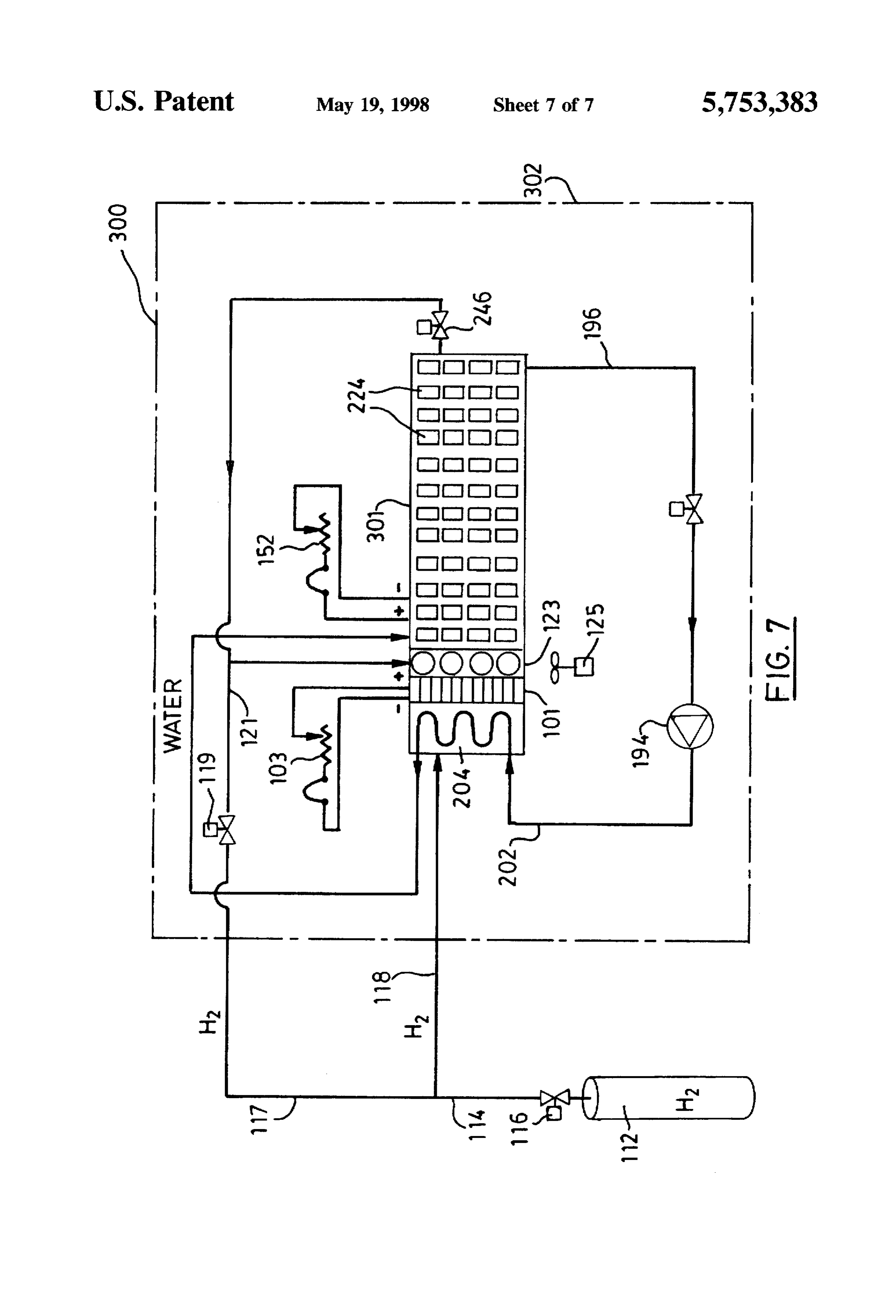
FIG. 6 is a schematic diagram of the flow diagram of the preferred embodiment, where the voltage of the two sub systems are plotted against a time scale common to that of combined coolant water stream through a heat exchanger the burner's temperature profile. One can observe that the and an active section of fuel cell stack of FIG. 5; and thermoelectric component of the voltage increases with the FIG. 7 is a schematic diagram of a third embodiment of 15 hot plate's temperature, and that the cooling fins remain the present invention. within 5° C. of the ambient temperature. The voltage output DETALED DESCRIPTION OF THE of the fuel cell is a function of the load imposed on the INVENTION system, with minimal or no correlation to the burner tem perature range.
Referring to FIGS. 1 and 2, there is shown the power 20 In the depicted experiment, the fuel cell stack 58 is a supply 10 and its constituent elements, namely a fuel cell 6-cell air-breathing polymer exchange membrane fuel cell stack 58, a burner module 34 and a thermoelectric module stack, and the thermoelectric element 18 is a FRIGICHIP
(TM) element from MELCOR. There had been no active
Thermoelectric module 40 has a housing 12 having fins 25 circulation of reactant gases for this demonstration. Ambient 14 on an outer side and a cavity 16 on an inner side. air at standard temperature and pressure had been convec Thermoelectric element 18 is mounted in cavity 16 which is tively consumed from the environment by the fuel cell stack closed with a thermal mass 20. Screws 22 fasten thermal and the catalytic burner. Hydrogen 99.995% pure had been mass 20 to housing 12. fed dead-ended to the power source at constant, near The burner module 34 comprises a housing 24 having an atmospheric pressure. The system had been self-starting and axial cavity 26 for receiving burner 28 and a bed of catalytic 30 provided power on-demand through repetitive cycles shown beads 31. Housing 24 has a flange 33 for spacing the burner on the graphs. The burner's thermal plate temperature (hot module 34 from the thermoelectric module 40. Flange 33 side of the thermoelectric module) had been maintained has a plurality of venting and breathing holes 35 to ensure within a 15° C. band below and above 250° C. through the adequate oxidant and fuel to the bed of catalytic beads 31 as 35 on/off modulation of the miniature proportioning valve well as venting the water vapor produced. Axial cavity 26 dispensing hydrogen.
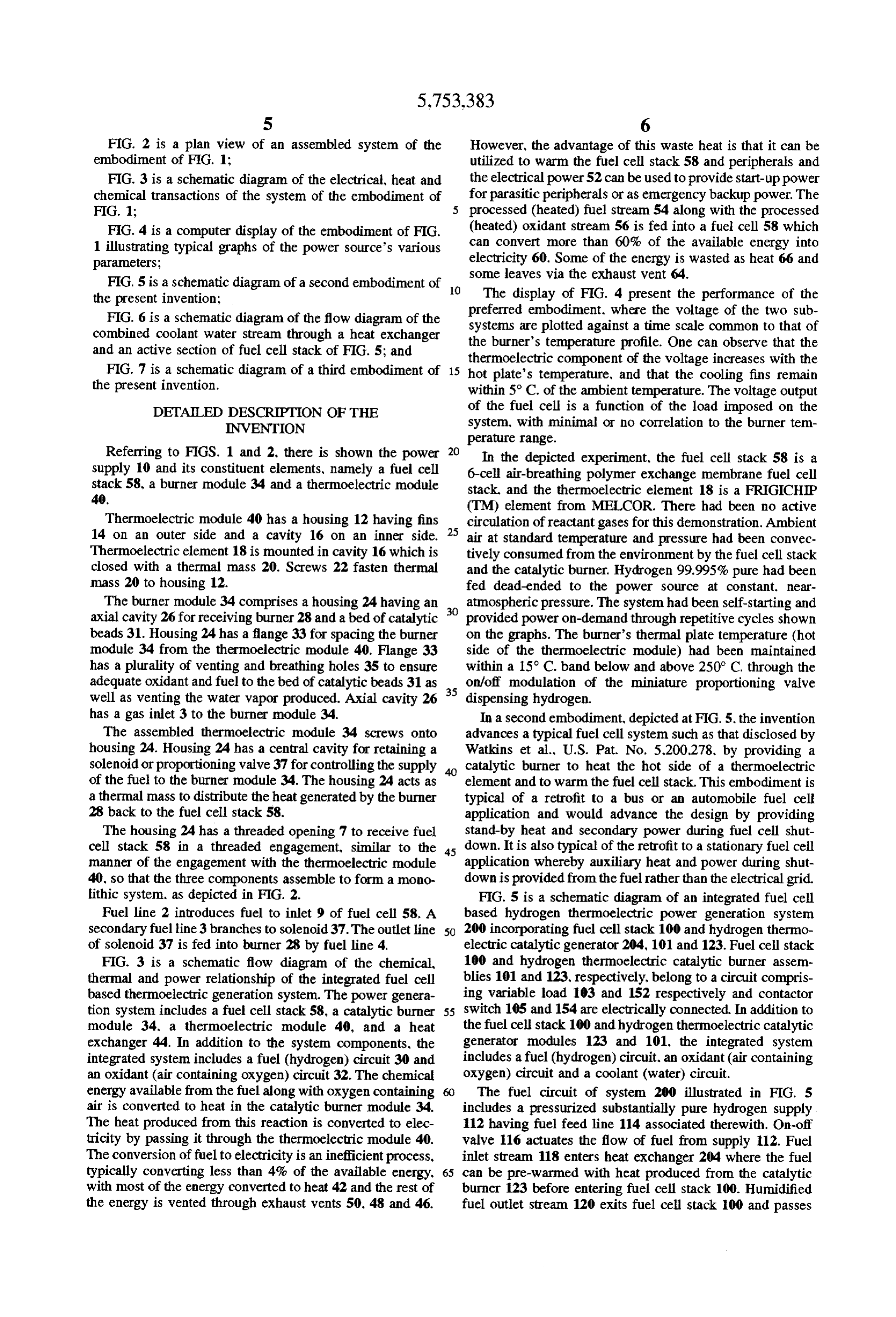
has a gas inlet 3 to the burner module 34. In a second embodiment, depicted at FIG. 5, the invention The assembled thermoelectric module 34 screws onto advances a typical fuel cell system such as that disclosed by housing 24. Housing 24 has a central cavity for retaining a Watkins et al., U.S. Pat. No. 5.200.278, by providing a solenoid or proportioning valve 37 for controlling the supply catalytic burner to heat the hot side of a thermoelectric of the fuel to the burner module 34. The housing 24 acts as element and to warm the fuel cell stack. This embodiment is athermal mass to distribute the heat generated by the burner typical of a retrofit to a bus or an automobile fuel cell 28 back to the fuel cell stack 58. application and would advance the design by providing The housing 24 has a threaded opening 7 to receive fuel stand-by heat and secondary power during fuel cell shut cell stack 58 in a threaded engagement, similar to the 45 down. It is also typical of the retrofit to a stationary fuel cell manner of the engagement with the thermoelectric module application whereby auxiliary heat and power during shut 40, so that the three components assemble to form a mono down is provided from the fuel rather than the electrical grid. lithic system, as depicted in FIG. 2. FIG. 5 is a schematic diagram of an integrated fuel cell Fuel line 2 introduces fuel to inlet 9 of fuel cell 58. A based hydrogen thermoelectric power generation system secondary fuel line 3 branches to solenoid 37. The outlet line 50 200 incorporating fuel cell stack 100 and hydrogen thermo of solenoid 37 is fed into burner 28 by fuel line 4, electric catalytic generator 204, 101 and 123. Fuel cell stack FIG. 3 is a schematic flow diagram of the chemical, 100 and hydrogen thermoelectric catalytic burner assem thermal and power relationship of the integrated fuel cell blies 101 and 123, respectively, belong to a circuit compris based thermoelectric generation system. The power genera ing variable load 103 and 152 respectively and contactor tion system includes a fuel cell stack 58, a catalytic burner 55 switch 105 and 154 are electrically connected. In addition to module 34, a thermoelectric module 40, and a heat the fuel cell stack 100 and hydrogen thermoelectric catalytic exchanger 44. In addition to the system components, the generator modules 123 and 101, the integrated system integrated system includes a fuel (hydrogen) circuit 30 and includes a fuel (hydrogen) circuit, an oxidant (air containing an oxidant (air containing oxygen) circuit 32. The chemical oxygen) circuit and a coolant (water) circuit. energy available from the fuel along with oxygen containing The fuel circuit of system 200 illustrated in FIG. 5 air is converted to heat in the catalytic burner module 34. includes a pressurized substantially pure hydrogen supply The heat produced from this reaction is converted to elec 112 having fuel feed line 114 associated therewith. On-off tricity by passing it through the thermoelectric module 40. valve 116 actuates the flow of fuel from supply 112. Fuel The conversion of fuel to electricity is an inefficient process, inlet stream 118 enters heat exchanger 204 where the fuel typically converting less than 4% of the available energy, 65 can be pre-warmed with heat produced from the catalytic with most of the energy converted to heat 42 and the rest of burner 123 before entering fuel cell stack 100. Humidified the energy is vented through exhaust vents 50. 48 and 46. fuel outlet stream 120 exits fuel cell stack 100 and passes
Page 12
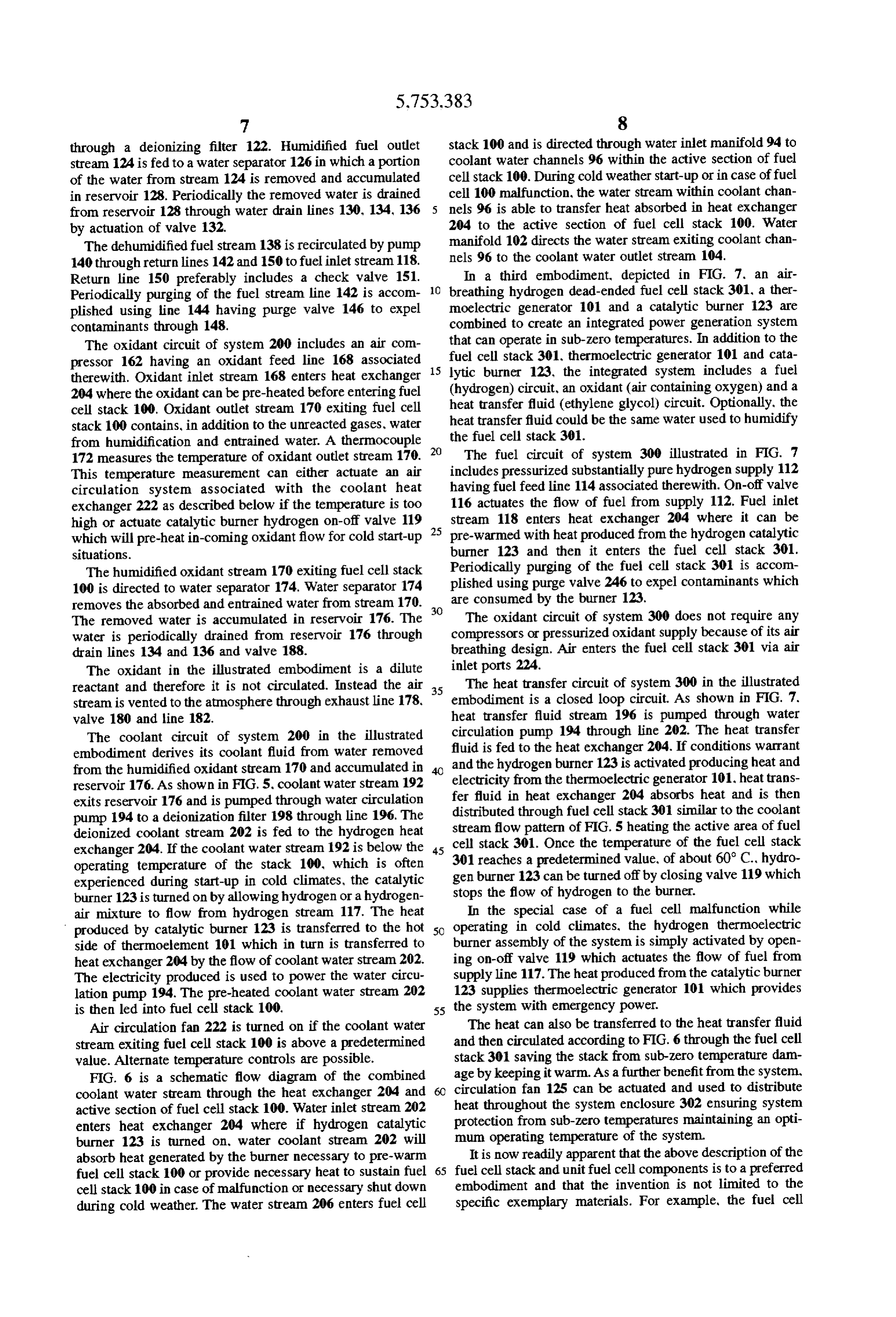
through a deionizing filter 122. Humidified fuel outlet stack 100 and is directed through water inlet manifold 94 to stream 124 is fed to a water separator 126 in which a portion coolant water channels 96 within the active section of fuel of the water from stream 124 is removed and accumulated cell stack 100. During cold weather start-up or in case of fuel in reservoir 128. Periodically the removed water is drained cell 100 malfunction, the water stream within coolant chan from reservoir 128 through water drain lines 130, 134, 136 5 nels 96 is able to transfer heat absorbed in heat exchanger by actuation of valve 132. 204 to the active section of fuel cell stack 100. Water The dehumidified fuel stream 138 is recirculated by pump manifold 102 directs the water stream exiting coolant chan 140 through return lines 142 and 150 to fuel inlet stream 118. nels 96 to the coolant water outlet stream 104. Return line 150 preferably includes a check valve 151. In a third embodiment, depicted in FIG. 7. an air Periodically purging of the fuel stream line 142 is accom O breathing hydrogen dead-ended fuel cell stack 301, a ther plished using line 144 having purge valve 146 to expel moelectric generator 101 and a catalytic burner 123 are contaminants through 148. combined to create an integrated power generation system The oxidant circuit of system 200 includes an air com that can operate in sub-zero temperatures. In addition to the pressor 162 having an oxidant feed line 168 associated 15 lytic cell fuel stack 301, thermoelectric generator 101 and cata burner 123, the integrated system includes a fuel therewith. Oxidant inlet stream 168 enters heat exchanger (hydrogen) 204 where the oxidant can be pre-heated before entering fuel heat transfercircuit, an oxidant (air containing oxygen) and a fluid (ethylene glycol) circuit. Optionally, the cell stack 100. Oxidant outlet stream 170 exiting fuel cell stack 100 contains, in addition to the unreacted gases, water heat transfer fluid could be the same water used to humidify from humidification and entrained water. A thermocouple 20 the fuel cell stack 301.
172 measures the temperature of oxidant outlet stream 170. The fuel circuit of system 300 illustrated in FIG. 7 This temperature measurement can either actuate an air includes pressurized substantially pure hydrogen supply 112 circulation system associated with the coolant heat having fuel feed line 114 associated therewith. On-off valve exchanger 222 as described below if the temperature is too 116 actuates the flow of fuel from supply 112. Fuel inlet high or actuate catalytic burner hydrogen on-off valve 119 25 stream 118 enters heat exchanger 204 where it can be which will pre-heat in-coming oxidant flow for cold start-up pre-warmed with heat produced from the hydrogen catalytic situations. burner 123 and then it enters the fuel cell stack 301. Periodically purging of the fuel cell stack 301 is accom
The humidified oxidant stream 170 exiting fuel cell stack plished 100 is directed to water separator 174. Water separator 174 using purge valve 246 to expel contaminants which removes the absorbed and entrained water from stream 170. 30 are consumed by the burner 123.
The removed water is accumulated in reservoir 176. The The oxidant circuit of system 300 does not require any water is periodically drained from reservoir 176 through compressors or pressurized oxidant supply because of its air drain lines 134 and 136 and valve 188. breathing design. Air enters the fuel cell stack 301 via air The oxidant in the illustrated embodiment is a dilute inlet ports 224.
reactant and therefore it is not circulated. Instead the air 35 The heat transfer circuit of system 300 in the illustrated stream is vented to the atmosphere through exhaust line 178, embodiment is a closed loop circuit. As shown in FIG. 7. valve 180 and line 182. heat transfer fluid stream 196 is pumped through water The coolant circuit of system 200 in the illustrated circulation pump 194 through line 202. The heat transfer embodiment derives its coolant fluid from water removed fluid is fed to the heat exchanger 204. If conditions warrant from the humidified oxidant stream 170 and accumulated in and the hydrogen burner 123 is activated producing heat and reservoir 176. As shown in FIG. 5, coolant water stream 192 electricity from the thermoelectric generator 101, heat trans exits reservoir 176 and is pumped through water circulation fer fluid in heat exchanger 204 absorbs heat and is then pump 194 to a deionization filter 198 through line 196. The distributed through fuel cell stack 301 similar to the coolant deionized coolant stream 202 is fed to the hydrogen heat stream flow pattern of FIG. 5 heating the active area of fuel exchanger 204. If the coolant water stream 192 is below the 45 cell
stack 301. Once the temperature of the fuel cell stack reaches a predetermined value, of about 60° C., hydro operating temperature of the stack 100, which is often experienced during start-up in cold climates, the catalytic gen burner 123 can be turned off by closing valve 119 which burner 123 is turned on by allowing hydrogen or a hydrogen stops the flow of hydrogen to the burner. air mixture to flow from hydrogen stream 117. The heat In the special case of a fuel cell malfunction while produced by catalytic burner 123 is transferred to the hot 50 operating in cold climates, the hydrogen thermoelectric side of thermoelement 101 which in turn is transferred to burner assembly of the system is simply activated by open heat exchanger 204 by the flow of coolant water stream 202. ing on-off valve 119 which actuates the flow of fuel from The electricity produced is used to power the water circu supply line 117. The heat produced from the catalytic burner lation pump 194. The pre-heated coolant water stream 202 123 supplies thermoelectric generator 101 which provides is then led into fuel cell stack 100, 55 the system with emergency power.
Air circulation fan 222 is turned on if the coolant water The heat can also be transferred to the heat transfer fluid stream exiting fuel cell stack 100 is above a predetermined and then circulated according to FIG. 6 through the fuel cell value. Alternate temperature controls are possible. stack 301 saving the stack from sub-zero temperature dam FIG. 6 is a schematic flow diagram of the combined age by keeping it warm. As a further benefit from the system, coolant water stream through the heat exchanger 204 and circulation fan 125 can be actuated and used to distribute active section of fuel cell stack 100. Water inlet stream 202 heat throughout the system enclosure 302 ensuring system enters heat exchanger 204 where if hydrogen catalytic protection from sub-zero temperatures maintaining an opti burner 123 is turned on, water coolant stream 202 will mum operating temperature of the system. absorb heat generated by the burner necessary to pre-warm It is now readily apparent that the above description of the fuel cell stack 100 or provide necessary heat to sustain fuel 65 fuel cell stack and unit fuel cell components is to a preferred cell stack 100 in case of malfunction or necessary shut down embodiment and that the invention is not limited to the during cold weather. The water stream 206 enters fuel cell specific exemplary materials. For example, the fuel cell
Page 13
stack could be assembled on the annular feed air breathing We claim:
design of Wilson U.S. Pat. No. 5.514,486 or Dahr's rectan 1. A method of generating heat and electrical energy, gular "chimney" grooves U.S. Pat. No. 5,242,764. Further. comprising the steps of the catalytic beads or pads of the burner could be replaced.
for example, by a catalytic mesh surface. The MELCOR supplying a first fuel to a burner for generating a tem thermoelectric elements could be replaced, for example, by perature differential across a thermoelectric element Brown-Teledyne elements. The fuel could be provided from generating electricity for secondary power, and for a hydride canister available from Hydrogen Consultants Inc. pre-heating a second fuel, said pre-heating comprising of Littleton. Colo... or from AF Sammer of Ringwood, N.J., primary heat.
rather than from a pressurized bottle. Further, the fuel could 10 supplying said second fuel to a fuel cell stack for gener also include methane or any other fuel from which hydrogen ating electricity for primary power and secondary heat. can be derived. 2. A method as claimed in claim 1 wherein said method The foregoing description of the invention has been further comprises a step of cooling one side of said ther presented for purposes of illustration and description and is moelectric element to increase said temperature differential. not intended to be exhaustive or to limit the invention to the 15 3. A method as claimed in claim 1 wherein said first fuel precise form disclosed. and obviously many modifications and said second fuel are supplied from a common source. and variations are possible in light of the above teaching. 4. A method as claimed in claim 1 wherein said method The embodiments were chosen and described in order to further comprises a step of regulating said first fuel to best explain the principles of the invention and its practical maintain an optimal operating temperature. application to thereby enable others skilled in the art to best 5. A method as claimed in claim 1 wherein said method utilize the invention in various embodiments and with further includes a step of extracting said primary and sec various modifications or omissions as are suited to the ondary power and heat.
particular use contemplated, without departing from the spirit and the scope of the invention. sk xk :: *k sk
Provenance
- Collection
- Patents citing this work
- Original assignee
- Hydrogenics Corp
- Pages
- 13
- Method
- pdftotext (the PDF's own text layer) + pdftoppm 300dpi page scans
- Patent office record
- patents.google.com →
- Source
- Google Patents citing-documents table
- Inventors
- Joseph Cargnelli; Pierre Rivard; Boyd Taylor; Hydrogenics Corp
- Published
- 1998-05-19
- Transcribed from
- patentimages.storage.googleapis.com →