patent · US4646702
Air pollution preventing device for internal combustion engine
3 March 1987
Page 1 — bibliographic record
United States Patent (19) 11 Patent Number: 4,646,702 Matsubara et al. 45) Date of Patent: Mar. 3, 1987 (54) AIR POLLUTION PREVENTING DEVICE Primary Examiner-Tony M. Argenbright FOR INTERNAL COMBUSTION ENGINE Attorney, Agent, or Firm-Gerald J. Ferguson, Jr.; (75) Inventors: Toshio Matsubara; Hideki Kakumoto; Michael P. Hoffman; Ronni S. Malamud Kazuyuki Okazaki, all of Hiroshima, 57) ABSTRACT
Japan 73 Assignee: Mazda Motor Corporation, Japan An air pollution preventing device having a canister for preventing fuel vapor formed in the fuel tank from 21 Appl. No.: 775,247 escaping into the atmosphere is provided with a feed 22 Filed: Sep. 12, 1985 back control detecting circuit which detects whether the feedback control of the air-fuel ratio of intake mix (30) Foreign Application Priority Data ture is effected, a temperature sensor which detects the Sep. 19, 1984 JP Japan ................................ 59-197385 fuel temperature and a purge control valve control 51) Int. Cl." ...................... F02M 25/08; F02D 41/14 circuit which receives outputs of the feedback control 52 U.S. Cl. ..................................... 123/520; 123/489 detecting circuit and the temperature sensor and con 58) Field of Search ................ 123/489, 518, 519, 520 trols the purge control valve so that the purge control valve is opened to permit introduction of the fuel vapor (56) References Cited trapped in the canister only when the feedback control
preset value and is opened irrespective of whether or not the feedback control is effected when the fuel tem
FOREIGN PATENT DOCUMENTS perature is not lower than the preset value.
119949 9/1980 Japan ................................... 123/520 10 Claims, 2 Drawing Figures
Page 2
Drawing sheet — no readable text.
Page 3
Drawing sheet — no readable text.
Page 4
opened or closed in response to whether or not the
AIR POLLUTION PREVENTING DEVICE FOR feedback control is effected.
INTERNAL COMBUSTION ENGINE However, in the conventional air pollution prevent ing devices, there arises various problems described
BACKGROUND OF THE INVENTION 5 later due to lack of consideration relating to the forma 1. Field of the Invention tion of fuel vapor and the control characteristics of the This invention relates to an air pollution preventing feedback control based on the output of the exhaust device for an internal combustion engine which pre sensor in the following points.
vents fuel vapor formed in the fuel tank from being 10 (1) The amount of fuel vapor formed in the fuel tank discharged into the air. increases as the fuel temperature rises, and the amount 2. Description of the Prior Art of fuel vapor purged from the canister into the intake There have been known air pollution preventing system increases with the increase in the fuel tempera devices for preventing fuel vapor formed in the fuel ture.
tank from being discharged into the air in which the fuel 15 (2) When the air-fuel ratio is feedback-controlled, if vapor is first trapped by a canister and then purged from the control value, i.e., the correction value of the fuel the canister and introduced into the intake system of the feeding amount, is excessively large, it takes a long time engine under the force of intake vacuum. However, for the air-fuel ratio to return to the preset value (e.g., when the trapped fuel vapor is turbulently introduced the stoichiometric value), thereby adversely affecting into the intake system, the air-fuel ratio of the intake 20 the control response, and at the same time, the fuel mixture introduced into the cylinders fluctuates by a feeding means can practically reduce the fuel only by a large amount which adversely affects combustion in the limited amount. Therefore, the maximum control value cylinders and adversely affects, in the case of an engine is generally set so as not to cause a large delay in control having a catalytic converter in the exhaust system, the response, and if the control value is to exceed the maxi cleaning performance of the catalytic converter. There 25 mum value, the control value is fixed at the maximum fore, in some of the known air pollution preventing value even in the feedback control range. In this case, devices of this type, a pressure responsive valve is pro the amount of fuel fed to the engine from the fuel feed vided to control the amount of fuel vapor to be purged ing means such as a fuel injector is fixed at a minimum. from the canister and introduced into the intake system (This condition will be referred to as "fuel-feed-ceil by the intake vacuum of the engine so that the amount 30 ing", hereinbelow.)
is increased as the intake vacuum of the engine is en (3) The amount of fuel fed to the intake system of the hanced, thereby restricting change in the air-fuel ratio engine is the sum of the amount of fuel fed from the fuel of the intake mixture caused by the fuel vapor. feeding means (this part of fuel will be referred to as However, it is difficult to precisely control the air 35 "main fuel”, hereinbelow) and the amount of fuel vapor fuel ratio by controlling the amount of the fuel vapor to purged from the canister. Therefore, in order to fix the be introduced into the intake system by means of the amount of fuel to be fed to the engine, the amount of the pressure responsive valve. There is disclosed in Japa main fuel must be reduced as the amount of the fuel nese Unexamined Patent Publication No. vapor purged from the canister increases. 51 (1976)-110130 an air pollution preventing device in 40 Accordingly, when the fuel temperature is increased, which a system for trapping fuel vapor by use of a increasing the amount of fuel vapor purged from the canister and feeding the trapped vapor fuel to the intake canister, and the amount of the main fuel is reduced system is combined with an air-fuel ratio control mecha with the increase in the amount of purged fuel vapor, nism for effecting feedback control of the air-fuel ratio the control value is apt to go to the maximum value to based on the output of an exhaust sensor provided in the 45 reduce the amount of the main fuel by the maximum exhaust passage, and the air-fuel ratio is controlled by amount, that is, the fuel-feed-ceiling is apt to occur. the air-fuel ratio control mechanism while the trapped When the control value is fixed at the maximum value, fuel vapor is purged from the canister into the intake the feedback control of the air-fuel ratio is interrupted system, whereby the air-fuel ratio can be controlled and the purge control valve is closed to interrupt the precisely even during the purging of the trapped fuel 50 purging of fuel vapor.
vapor from the canister. On the other hand, when the operating range of the However, practically, the feedback control of the engine is changed to a high-speed, heavy-load range by air-fuel ratio based on the output of the exhaust sensor is depression of the accelerator pedal while the control effected only in the low-speed, light-load operating value is fixed at the maximum value, and then reverts to range of the engine in which exhaust performance is apt 55 the feedback control range, the air-fuel ratio of the to be deteriorated, and is not effected in other operating intake mixture in the intake passage is lowered and the ranges in order to increase engine output power. Ac control value is reduced below the maximum value, and cordingly, in order to restrict change in the air-fuel ratio at the same time, the feedback control is started again brought about by the fuel vapor introduced into the and the purge control valve is opened to start purging intake system from the canister by means of feedback 60 of fuel vapor from the canister again. That is, when the control based on the output of the exhaust sensor as in accelerator pedal is repeatedly depressed and released the device disclosed in the above Japanese unexamined while the fuel temperature is high, the feedback control patent publication, the feedback control range in which of the air-fuel ratio is repeatedly effected and inter the feedback control of the air-fuel ratio is to be effected rupted and the purge control valve is repeatedly opened and the fuel vapor purging range in which fuel vapor 65 and closed, causing surging, whereby durability of the trapped in the canister is to be purged therefrom and purge control valve is deteriorated and the operating introduced into the intake system must overlap each performance of the engine is adversely affected since other. This requires a purge control valve which is the air-fuel ratio fluctuates between rich and lean.
Page 5
13 detects the boosting pressure in the intake passage 2
SUMMARY OF THE INVENTION and outputs a boost signal S3.
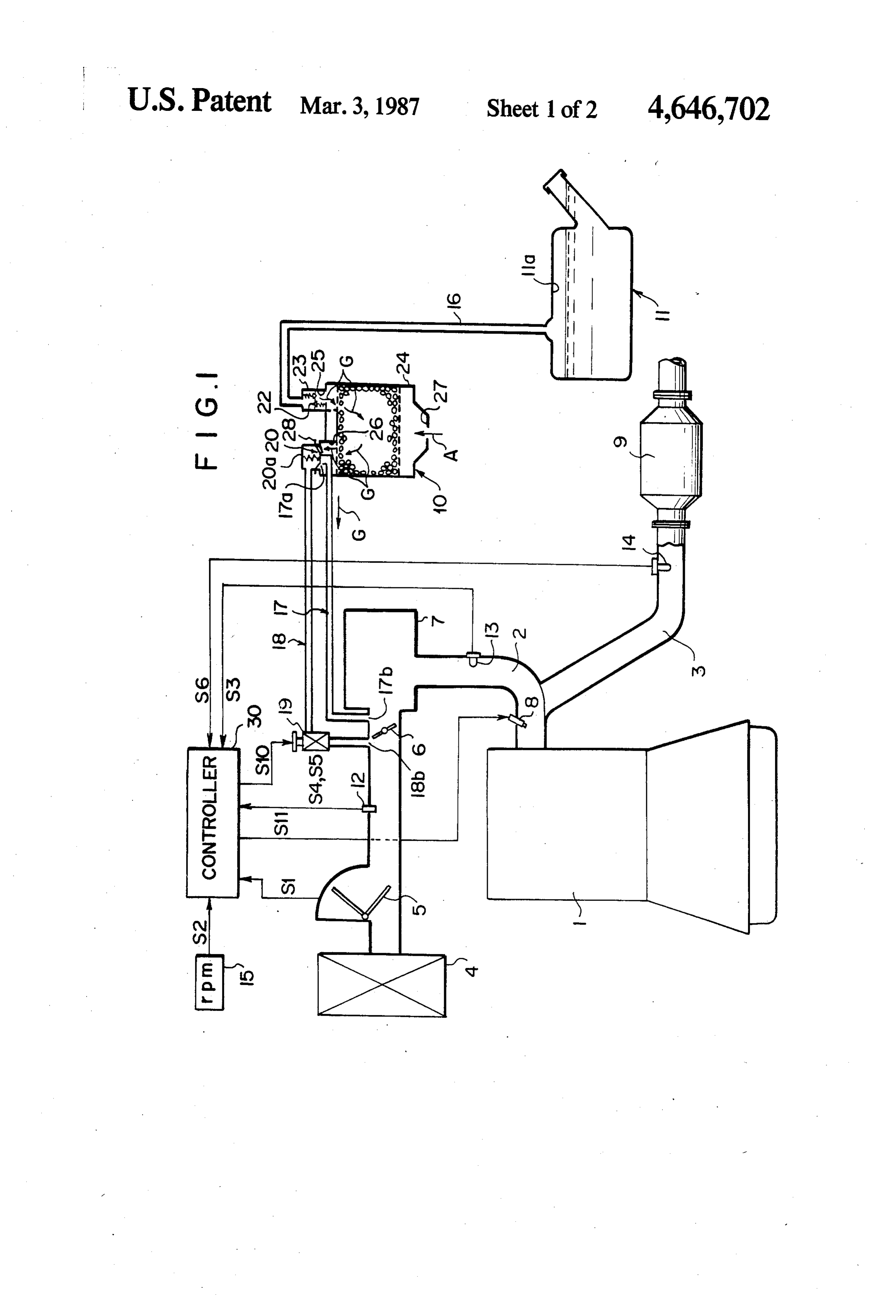
In view of the foregoing observations and descrip The exhaust passage 3 is provided with a catalytic converter 9, and an oxygen sensor 14 (as the exhaust tion, the primary object of the present invention is to sensor) is provided in the exhaust passage 3 upstream of provide an air pollution preventing device for an inter the catalytic converter 9. The oxygen sensor 14 detects nal combustion engine in which purging of fuel vapor the oxygen concentration from the canister into the intake system is controlled by in the exhaust from the engine a purge control valve and the air-fuel ratio of the intake 1 and outputs an oxygen concentration signal S6. A fuel tank 11 is connected to the intake passage 2 by mixture is feedback-controlled on the basis of the output of an exhaust sensor, which device can prevent the O way of a canister 10 comprising a casing 24 filled with surging of the purge control valve which is apt to occur tank 11 ischarcoal.
activated Fuel vapor G formed in the fuel when the fuel temperature is high and the amount of canister 10 absorbed and is by the activated charcoal in the purged therefrom into the intake pas fuel vapor formed in the fuel tank is relatively large, thereby improving durability of the purge control valve 15 sage 2 in a known manner. The canister 10 is provided, in the top wall of the casing 24, with a fuel vapor inlet and operating performance of the engine.
The air pollution preventing device in accordance thewhich
fuel is communicated with an upper space 11a in tank 11 by way of a fuel vapor passage 16. The with the present invention is provided with a feedback fuel vapor passage control detecting means which detects whether the inlet 25 by way of 16 is connected to the fuel vapor a pair of check valves 22 and 23 feedback control is effected or the feedback control means is operating, a temperature sensor which detects which are disposed side by side and arranged to permit the fuel temperature or a temperature related to the fuel formed inopposite flows in directions. A fuel vapor outlet 26 is temperature (in this specification, the term "fuel tem and is connected to theof the the top wall casing 24 of the canister 10 intake passage 2 between the perature' broadly includes any temperatures related to throttle valve 6 and the surge tank 7 by way of a fuel the fuel temperature), and a purge control valve control 25 vapor purging passage 17. The fuel vapor purging pas means which receives the output of the feedback con sage 17 is provided with a valve seat 28 which is formed trol detecting means and the temperature sensor and on one end 17a of the fuel vapor purging passage 17 and controls the purge control valve so that the purge con opens in the fuel vapor outlet 26 of the canister 10, and trol valve is opened to permit introduction of the fuel is connected to the intake passage 2 at the other end 17b vapor trapped in the canister only when the feedback 30 thereof which opens in the intake passage 2 downstream control is being effected when the fuel temperature is of the throttle valve 6 and upstream of the surge tank 7. lower than a preset value and is opened irrespective of On the valve seat 28 is mounted a diaphragm type pres whether the feedback control is being effected when the sure responsive valve 20 which is actuated under the fuel temperature is not lower than the preset value. force of intake vacuum introduced by way of an intake In accordance with the present invention, when the 35 vacuum introduction passage 18. The intake vacuum fuel temperature is high, where the amount of fuel introduction passage 18 opens (18b) in the intake pas vapor formed in the fuel tank is large and the feedback sage 2 in a suitable position upstream of the throttle control of the air-fuel ratio is repeated due to repeated valve 6 so that the pressure responsive valve 20 is actu operation of the accelerator pedal, the purge control ated to open the valve seat 28 under the force of intake valve is kept opened and accordingly surging of the vacuum transmitted thereto by way of the intake vac purge control valve is prevented. uum introduction passage 18 when the engine load is BRIEF DESCRIPTION OF THE DRAWINGS heavier than a preset value and otherwise keeps the valve seat 28 closed. In this embodiment, the intake
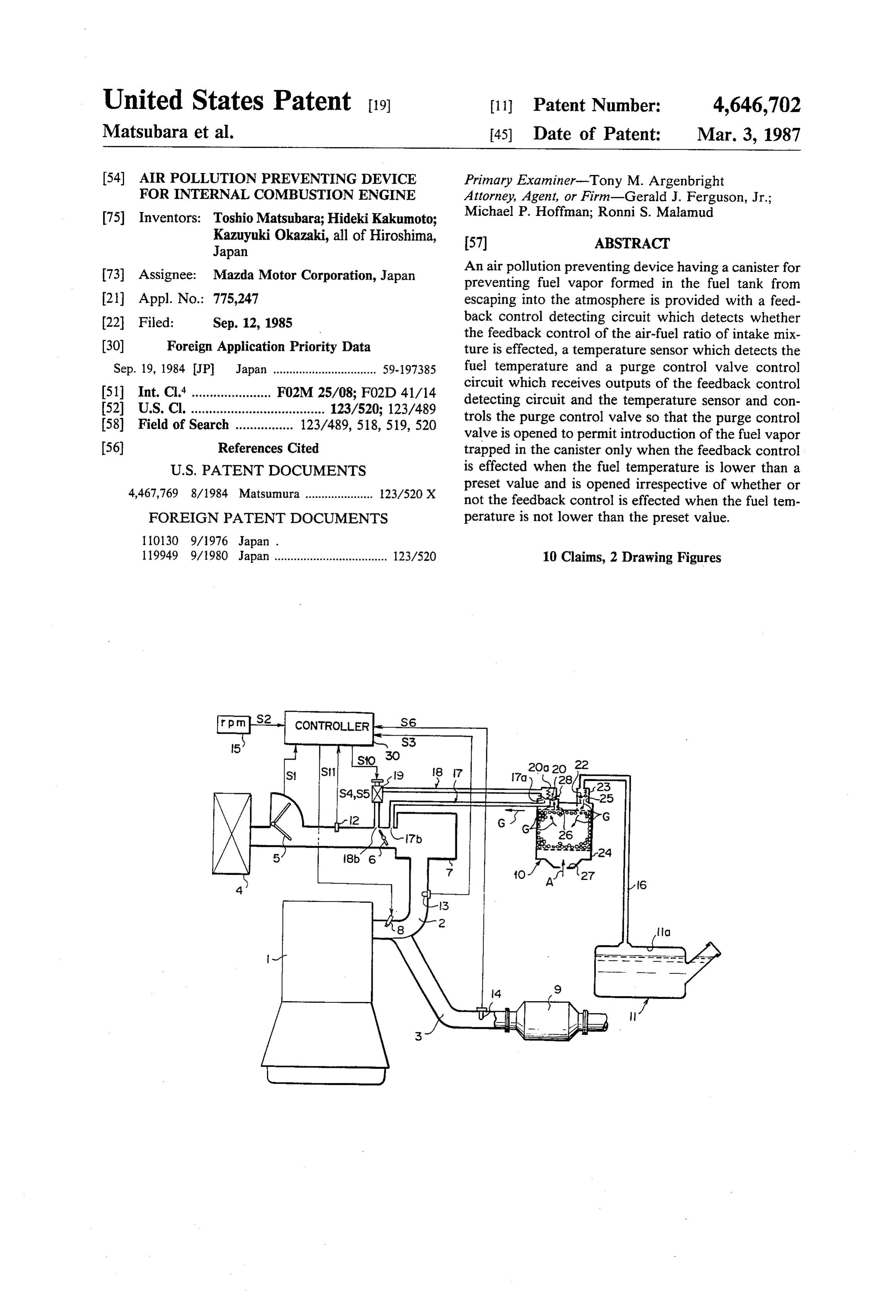
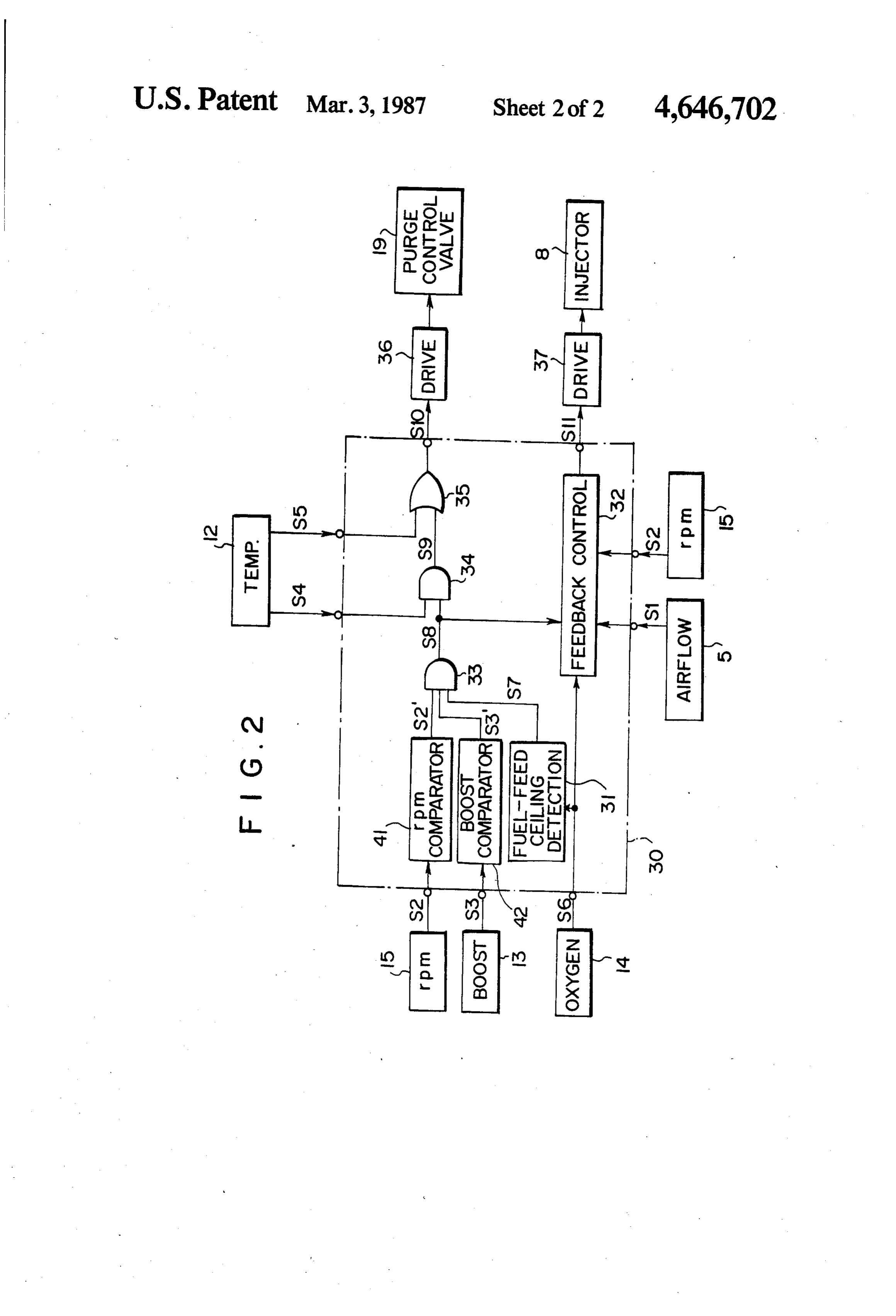
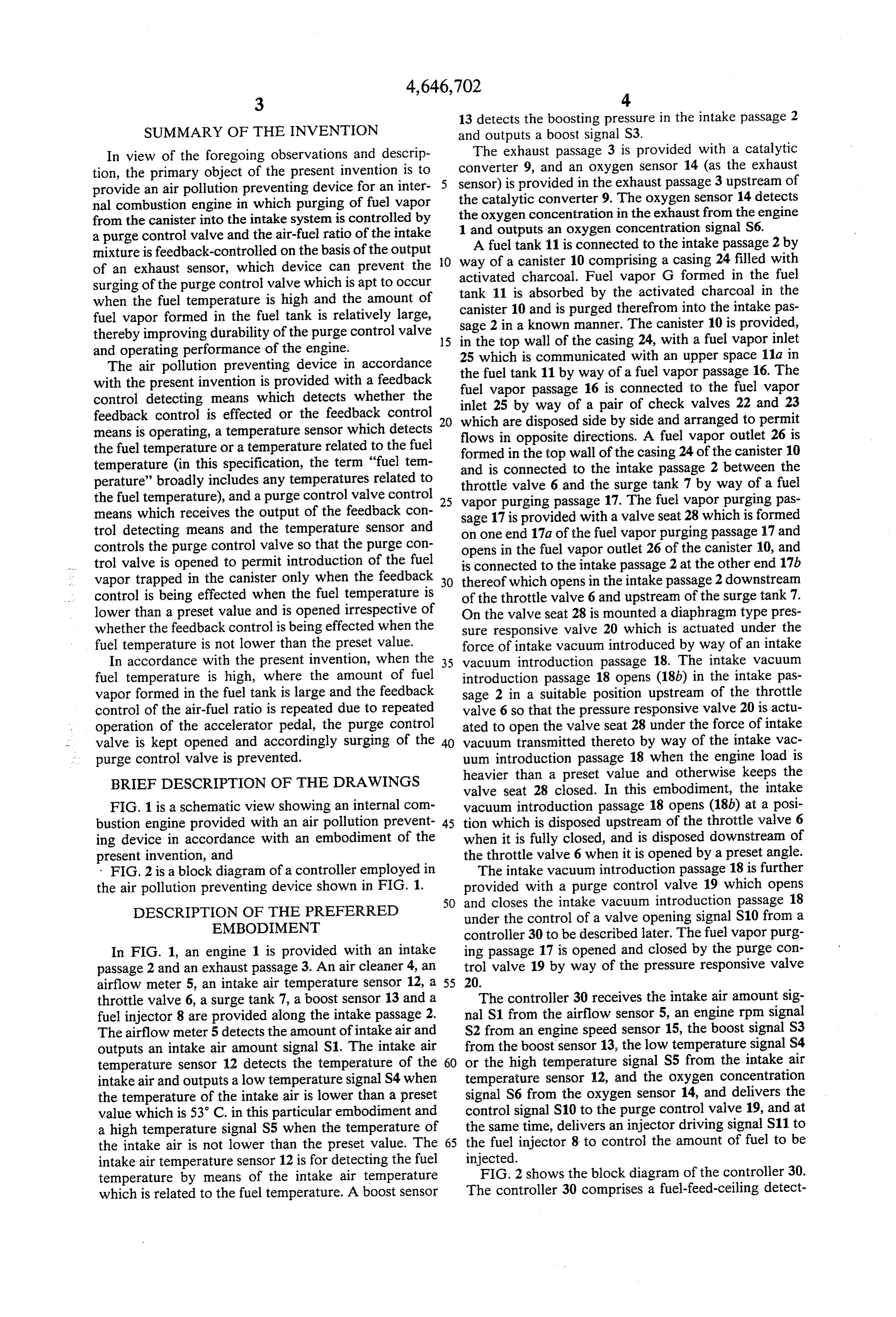
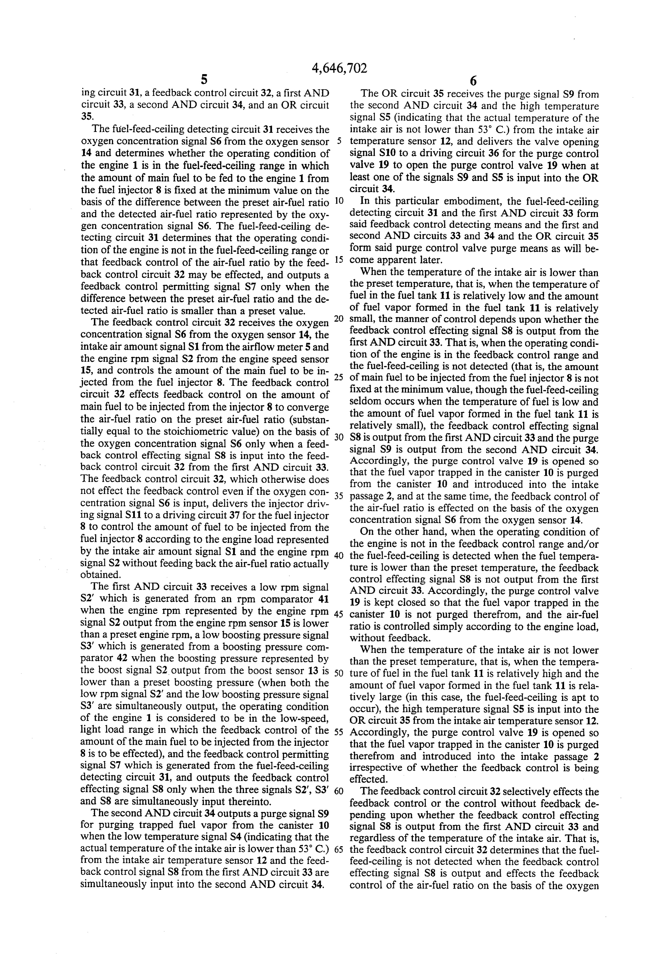
FIG. 1 is a schematic view showing an internal com vacuum introduction passage 18 opens (18b) at a posi bustion engine provided with an air pollution prevent 45 tion which is disposed upstream of the throttle valve 6 ing device in accordance with an embodiment of the when it is fully closed, and is disposed downstream of present invention, and the throttle valve 6 when it is opened by a preset angle. FIG. 2 is a block diagram of a controller employed in The intake vacuum introduction passage 18 is further the air pollution preventing device shown in FIG. 1. provided with a purge control valve 19 which opens 50 and closes the intake vacuum introduction passage 18
DESCRIPTION OF THE PREFERRED under the control of a valve opening signal S10 from a EMBODIMENT controller 30 to be described later. The fuel vapor purg In FIG. 1, an engine 1 is provided with an intake ing passage 17 is opened and closed by the purge con passage 2 and an exhaust passage 3. An air cleaner 4, an trol valve 19 by way of the pressure responsive valve airflow meter 5, an intake air temperature sensor 12, a 55 20.
throttle valve 6, a surge tank 7, a boost sensor 13 and a The controller 30 receives the intake air amount sig fuel injector 8 are provided along the intake passage 2. nal S1 from the airflow sensor 5, an engine rpm signal The airflow meter 5 detects the amount of intake air and S2 from an engine speed sensor 15, the boost signal S3 outputs an intake air amount signal S1. The intake air from the boost sensor 13, the low temperature signal S4 temperature sensor 12 detects the temperature of the 60 or the high temperature signal S5 from the intake air intake air and outputs a low temperature signal S4 when temperature sensor 12, and the oxygen concentration the temperature of the intake air is lower than a preset signal S6 from the oxygen sensor 14, and delivers the value which is 53 C. in this particular embodiment and control signal S10 to the purge control valve 19, and at a high temperature signal S5 when the temperature of the same time, delivers an injector driving signal S11 to the intake air is not lower than the preset value. The 65 the fuel injector 8 to control the amount of fuel to be intake air temperature sensor 12 is for detecting the fuel injected.
temperature by means of the intake air temperature FIG. 2 shows the block diagram of the controller 30. which is related to the fuel temperature. A boost sensor The controller 30 comprises a fuel-feed-ceiling detect
Page 6
ing circuit 31, a feedback control circuit 32, a first AND The OR circuit 35 receives the purge signal S9 from circuit 33, a second AND circuit 34, and an OR circuit the second AND circuit 34 and the high temperature 35. signal S5 (indicating that the actual temperature of the The fuel-feed-ceiling detecting circuit 31 receives the intake air is not lower than 53 C.) from the intake air oxygen concentration signal S6 from the oxygen sensor 5 temperature sensor 12, and delivers the valve opening 14 and determines whether the operating condition of signal S10 to a driving circuit 36 for the purge control the engine 1 is in the fuel-feed-ceiling range in which valve 19 to open the purge control valve 19 when at the amount of main fuel to be fed to the engine 1 from least one of the signals S9 and S5 is input into the OR the fuel injector 8 is fixed at the minimum value on the circuit 34.
basis of the difference between the preset air-fuel ratio 10 In this particular embodiment, the fuel-feed-ceiling and the detected air-fuel ratio represented by the oxy detecting circuit 31 and the first AND circuit 33 form gen concentration signal S6. The fuel-feed-ceiling de said feedback control detecting means and the first and tecting circuit 31 determines that the operating condi second AND circuits 33 and 34 and the OR circuit 35 tion of the engine is not in the fuel-feed-ceiling range or form said purge control valve purge means as will be that feedback control of the air-fuel ratio by the feed 15 come apparent later.
back control circuit 32 may be effected, and outputs a When the temperature of the intake air is lower than feedback control permitting signal S7 only when the the preset temperature, that is, when the temperature of difference between the preset air-fuel ratio and the de fuel in the fuel tank 11 is relatively low and the amount tected air-fuel ratio is smaller than a preset value. of fuel vapor formed in the fuel tank 11 is relatively 20 small, the manner of control depends upon whether the
The feedback control circuit 32 receives the oxygen concentration signal S6 from the oxygen sensor 14, the feedback control effecting signal S8 is output from the intake air amount signal S1 from the airflow meter 5 and first AND circuit 33. That is, when the operating condi tion of the engine is in the feedback control range and the engine rpm signal S2 from the engine speed sensor the fuel-feed-ceiling is not detected (that is, the amount 15, and controls the amount of the main fuel to be in 25 of main jected from the fuel injector 8. The feedback control fixed at the fuel to be injected from the fuel injector 8 is not circuit 32 effects feedback control on the amount of minimum value, though the fuel-feed-ceiling main fuel to be injected from the injector 8 to converge the amount of when seldom occurs fuel the temperature of fuel is low and vapor formed in the fuel tank 11 is the air-fuel ratio on the preset air-fuel ratio (substan relatively small), the feedback tially equal to the stoichiometric value) on the basis of 30 S8is output from the first AND control circuit effecting signal 33 and the purge the oxygen concentration signal S6 only when a feed signal S9 is output from the second AND circuit 34. back control effecting signal S8 is input into the feed Accordingly, the purge control valve 19 is opened so back control circuit 32 from the first AND circuit 33.
The feedback control circuit 32, which otherwise does that the fuel vapor trapped in the canister 10 is purged from the canister 10 and introduced into the intake not effect the feedback control even if the oxygen con 35 passage 2, and at the same time, the feedback control of centration signal S6 is input, delivers the injector driv the air-fuel ratio is effected on the basis of the oxygen ing signal S11 to a driving circuit 37 for the fuel injector concentration signal S6 from the oxygen sensor 14.
8 to control the amount of fuel to be injected from the fuel injector 8 according to the engine load represented theOnengine the other hand, when the operating condition of is not in the feedback control range and/or by the intake air amount signal S1 and the engine rpm 40 the fuel-feed-ceiling signal S2 without feeding back the air-fuel ratio actually ture is lower than theis preset detected when the fuel tempera temperature, the feedback obtained. control effecting signal S8 is not output from the first The first AND circuit 33 receives a low rpm signal AND circuit 33. Accordingly, the purge control valve S2' which is generated from an rpm comparator 41 19 is kept closed so that the fuel vapor trapped in the when the engine rpm represented by the engine rpm 45 canister 10 is not purged therefrom, and the air-fuel signal S2 output from the engine rpm sensor 15 is lower ratio is controlled than a preset engine rpm, a low boosting pressure signal without feedback. simply according to the engine load, S3' which is generated from a boosting pressure com When the temperature of the intake air is not lower parator 42 when the boosting pressure represented by than the preset temperature, that is, when the tempera the boost signal S2 output from the boost sensor 13 is 50 ture of fuel in the fuel tank 11 is relatively high and the lower than a preset boosting pressure (when both the amount of fuel vapor formed in the fuel tank 11 is rela low rpm signal S2’ and the low boosting pressure signal tively large (in this case, the fuel-feed-ceiling is apt to S3' are simultaneously output, the operating condition occur), the high temperature signal S5 is input into the of the engine 1 is considered to be in the low-speed, OR circuit 35 from the intake air temperature sensor 12. light load range in which the feedback control of the 55 Accordingly, the purge control valve 19 is opened so amount of the main fuel to be injected from the injector that the fuel vapor trapped in the canister 10 is purged 8 is to be effected), and the feedback control permitting therefrom and introduced into the intake passage 2 signal S7 which is generated from the fuel-feed-ceiling irrespective of whether the feedback control is being detecting circuit 31, and outputs the feedback control effected.
effecting signal S8 only when the three signals S2, S3 60 The feedback control circuit 32 selectively effects the and S8 are simultaneously input thereinto. feedback control or the control without feedback de The second AND circuit 34 outputs a purge signal S9 pending upon whether the feedback control effecting for purging trapped fuel vapor from the canister 10 signal S8 is output from the first AND circuit 33 and when the low temperature signal S4 (indicating that the regardless of the temperature of the intake air. That is, actual temperature of the intake air is lower than 53 C.) 65 the feedback control circuit 32 determines that the fuel from the intake air temperature sensor 12 and the feed feed-ceiling is not detected when the feedback control back control signal S8 from the first AND circuit 33 are effecting signal S8 is output and effects the feedback simultaneously input into the second AND circuit 34. control of the air-fuel ratio on the basis of the oxygen
Page 7
concentration signal S6 output from the oxygen sensor 4. An air pollution preventing device as defined in 14. On the other hand, when the feedback control ef claim 3 further comprising means for detecting that the fecting signal S8 is not output, the feedback control engine speed is lower than a preset value and means for circuit 32 determines that the fuel-feed-ceiling is de detecting that the engine load is lighter than a preset tected and controls the air-fuel ratio without feedback 5 value, the preset values of the engine speed and the irrespective of the oxygen concentration signal S6. engine load defining said predetermined low-speed, The fuel-feed-ceiling is released by a depression of light-load range.
the accelerator pedal, changing the operating condition claim 5. An air pollution preventing device as defined in of the engine from the low-speed, light-load range in 10 provided 4 in which said exhaust system of the engine is which the feedback control of the air-fuel ratio is ef. with a catalytic converter, said exhaust sensor fected to the high-speed, heavy-load range, and then is an oxygen sensor for measuring the oxygen concen releasing the accelerator pedal to return the operating tration in the exhaust gas upstream of the catalytic con condition to the low-speed, light-load range or the feed verter, andthat said minimum-fuel-feed detecting means back control range. Therefore, when the accelerator 15 determines the amount of main fuel to be fed to the pedal is repeatedly depressed and released, feedback difference betweenfixed engine has been at a minimum value when the the preset air-fuel ratio and the ac control and control without feedback are alternately tual air-fuel ratio derived from the oxygen concentra repeated.
However, in the embodiment described above, the tion in the exhaust gas measured by the oxygen sensor is purge control valve 19 is kept open when the fuel tem 20 larger than a predetermined value. 6. An air pollution preventing device as defined in perature is high irrespective of whether the feedback claim 1 in which said feedback control means receives control is effected. Therefore, the purge control valve outputs from an engine speed sensor for detecting the 19 is not repeatedly opened and closed even if the feed engine rpm and an engine load sensor for detecting the back control is repeatedly effected and interrupted and engine load, and operates when the operating condition accordingly surging of the purge control valve 19 can 25 of the engine is in a predetermined low-speed, light-load be prevented. range, the predetermined low-speed, light-load range In the embodiment described above, the temperature being said particular operating range of the engine. of the intake air is detected instead of the fuel tempera 7. An air pollution preventing device as defined in ture. However, the temperature of the fuel in the fuel claim 6 further comprising means for detecting that the tank 11 may be detected directly or the ambient temper engine speed is lower than a preset value and means for ature may be detected instead. detecting that the engine load is lighter than a preset We claim: value, the preset values of the engine speed and the 1. An air pollution preventing device for an internal engine load defining said predetermined low-speed, combustion engine comprising a feedback control light-load range.
means for controlling the air-fuel ratio of intake mixture 35 8. An air pollution preventing device as defined in to converge on a preset value in a particular operating claim 1 in which said canister is connected to the intake range of the engine according to an output of an exhaust system by way of a purge passage which is connected to sensor provided in the exhaust system of the engine, a the intake system downstream of the throttle valve at canister for trapping fuel vapor formed in a fuel tank, a one end and to a fuel vapor outlet of the canister at the purge control valve which is opened to permit purging 40 other end, a pressure responsive valve means is pro of the trapped fuel vapor from the canister and intro vided to open and close the purge passage under the duction of the same into the intake system of the engine, force of the intake vacuum exerted thereon by way of a feedback control detecting means for detecting that an intake vacuum introduction passage, and said purge the feedback control means is operating, a temperature control valve is provided in the intake vacuum intro detecting means for detecting the fuel temperature in 45 duction passage to control the intake vacuum exerted the fuel tank, and a purge control valve control means on the pressure responsive valve means. which opens the purge control valve when the feedback 9. An air pollution preventing device as defined in control means is operating and the fuel temperature in claim 8 in which said intake vacuum introduction pas the fuel tank is lower than a preset value while opening sage opens in the intake system at a position which is the same when the fuel temperature in the fuel tank is 50 disposed upstream of the throttle valve when it is fully not lower than the preset value irrespective of whether closed, and is disposed downstream of the throttle valve the feedback control means is operating. when it is opened by a preset angle. 2. An air pollution preventing device as defined in 10. An air pollution preventing device for an internal claim 1 in which said temperature detecting means de combustion engine, comprising tects the fuel temperature in the fuel tank from the 55 a purge control valve which is opened to permit temperature of intake air. introduction of fuel vapor formed in the fuel tank 3. An air pollution preventing device as defined in of the engine into the intake system of the engine claim 1 further comprises a feedback control permitting and is closed to prevent the same, means which receives an engine rpm signal from an an engine speed sensor for detecting the engine rpm, engine speed sensor, an engine load signal from an en 60 an intake vacuum sensor for detecting the engine load gine load sensor and a minimum-fuel-feed signal from a through the intake vacuum, minimum-fuel-feed detecting means which detects that a catalytic converter provided in the exhaust system the amount of main fuel to be fed to the engine has been of the engine, fixed at a minimum value, and outputs a feedback con an exhaust sensor provided in the exhaust system trol permitting signal when the operating condition of 65 upstream of the catalytic converter, the engine is in a predetermined low-speed, light-load an airflow meter for detecting the amount of intake range and the amount of main fuel to be fed to the en air flowing in the intake passage of the intake sys gine is not fixed at the minimum value. ten
Page 8
an intake air temperature sensor which detects the vacuum sensor and the minimum-fuel-feed detect intake air temperature and outputs a low tempera ing means and outputs a feedback control permit ture signal when the intake air temperature is lower ting signal when the operating condition of the than a preset value and a high temperature signal engine derived from the output of the engine speed when the intake air temperature is not lower than sensor and the intake vacuum sensor is in a prede the preset value, termined low-speed, light-load range, and the a feedback control means which receives the output amount of main fuel fed to the engine is not fixed at of the exhaust sensor and effects feedback control to converge the actual air-fuel ratio derived from the minimum value, and the output of the exhaust sensor on a preset air-fuel 10 a purge control valve control means which receives ratio, the outputs of the feedback control permitting a minimum fuel-feed-detecting means which receives means and the intake air temperature sensor, and the output of the exhaust sensor and determines opens the purge control valve only when the feed that the amount of main fuel fed to the engine has back control permitting signal is input when the been fixed at a minimum value when the difference 15 low temperature signal is input from the intake air between the actual airfuel ratio derived from the temperature sensor, and opens the purge control output of the exhaust sensor and the preset air-fuel valve irrespective of the feedback control permit ratio is larger than a predetermined value, ting signal when the high temperature signal is a feedback control permitting means which receives input from the intake air temperature sensor. the outputs of the engine speed sensor, the intake 20 k is a k is
Provenance
- Collection
- Cited prior art
- Original PDF
- patentimages.storage.googleapis.com →
- Filed
- 1985-09-12
- Pages
- 8
- Method
- pdftotext (the PDF's own text layer) + pdftoppm 300dpi page scans
- Source
- Google Patents bibliographic record
- Granted
- 1987-03-03
- Inventors
- Toshio Matsubara; Hideki Kakumoto; Kazuyuki Okazaki; Mazda Motor Corp
- Transcribed from
- patentimages.storage.googleapis.com →