patent · US6336430B2
Hydrogen generating apparatus
8 January 2002
Page 1 — bibliographic record
(12) United States Patent (10) Patent No.: US 6,336,430 B2 de Souza et al. (45) Date of Patent: *Jan. 8, 2002
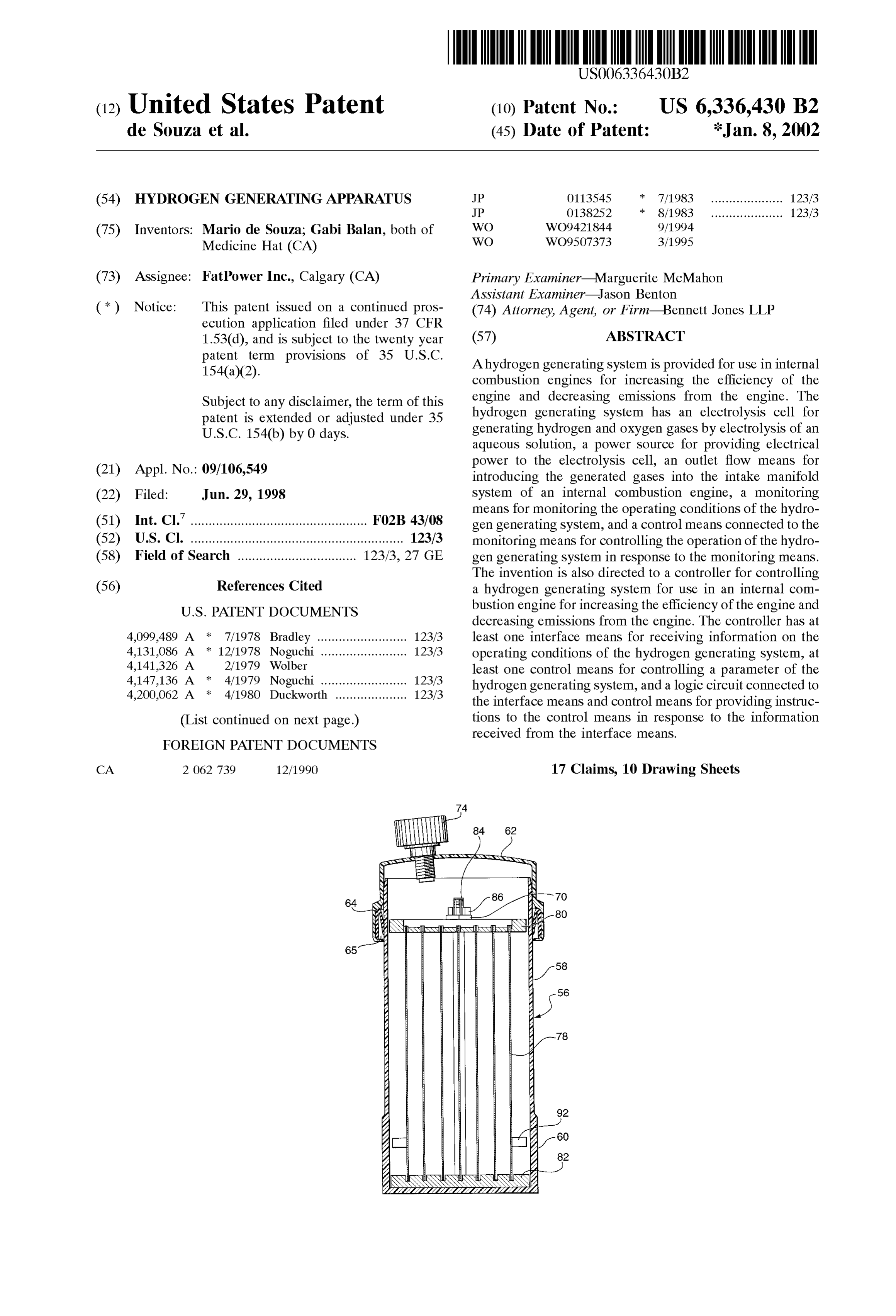
(54) HYDROGEN GENERATING APPARATUS JP O113545 7/1983 .................... 123/3 JP O138252 8/1983 .................... 123/3 (75) Inventors: Mario de Souza; Gabi Balan, both of WO WO9421844 9/1994 Medicine Hat (CA) WO WO9507373 3/1995 (73) Assignee: FatPower Inc., Calgary (CA) Primary Examiner Marguerite McMahon ASSistant Examiner Jason Benton (*) Notice: This patent issued on a continued pros- (74) Attorney, Agent, or Firm-Bennett Jones LLP ecution application filed under 37 CFR 1.53(d), and is subject to the twenty year (57) ABSTRACT
F.55rm provisions of 35 U.S.C. A hydrogen generating System is provided for use in internal combustion engines for increasing the efficiency of the
Subject to any disclaimer, the term of this engine and decreasing emissions from the engine. The patent is extended or adjusted under 35 hydrogen generating System has an electrolysis cell for U.S.C. 154(b) by 0 days. generating hydrogen and oxygen gases by electrolysis of an aqueous Solution, a power Source for providing electrical power to the electrolysis cell, an outlet flow means for (21) Appl. No.: 09/106,549 introducing the generated gases into the intake manifold (22) Filed: Jun. 29, 1998 System of an internal combustion engine, a monitoring means for monitoring the operating conditions of the hydro (51) Int. CI.7 - ------ ----- --------- -- --- ------ --- ----------- --- FO2B 43/08 gen generating System, and control CS connected to the
(52) U.S. Cl. ........................................................... 123/3 monitoring means for controlling the operation of the hydro (58) Field of Search ................................. 123/3, 27 GE gen generating System in response to the monitoring means. The invention is also directed to a controller for controlling (56) References Cited a hydrogen generating System for use in an internal com bustion engine for increasing the efficiency of the engine and
4,099,489 A * 7/1978 Bradley ......................... 123/3 least one interface means for receiving information on the 4,131,086 A * 12/1978 Noguchi ........................ 123/3 operating conditions of the hydrogen generating System, at 4,141,326 A 2, 1979 Wolbert least one control means for controlling a parameter of the
hydrogen generating system, and a logic circuit connected to 4.200,062 A 4/1980 Duckworth .................... 123/3 the interface means and control means for providing instruc (List continued on next page.) tions to the control means in response to the information received from the interface means.
FOREIGN PATENT DOCUMENTS
CA 2O62 739 12/1990 17 Claims, 10 Drawing Sheets
Page 2
: 5,359.968 A 11/1994 Shiraishi 4,332.219 A : 6/1982 Gonzalez ....................... 123/3 5,360,461. A 11/1994 Meinzer A y ----- ----- ------ --- -------- 123/3 5,370,097 A * 12/1994 Davis .................... 123/27 GE 2 - . 12 f ynn 5,450,822 A 9/1995 Cunningham 4,541,397 A * 9/1985 Young ................... 123/27 GE 5,452,688 A 9/1995 Rose ............................. 123/3 4,574,752 A * 3/1986 Reichert, Jr. et al.. 123/198 DB 5,458,095 A * 10/1995 Post et all 4,594,990 A * 6/1986 Batchelor 123/27 GE 5513,600 A 5/1996 E. C a 4,596.211 A * 6/1986 Szloboda ...... ... 123/27 GE 2- - -2 eeS 4,750,453 A :* 6/1988 Valdespino .................... 123/3 5,526,786 A * 6/1996 Becket al. ............. 123/27 GE
5,143,025 A 9/1992 Munday 5,711,865 A 1/1998 Caesar
5,178,118 A 1/1993 Nakamats 5,799.624 A 9/1998 Hsieh 5,224,457 A * 7/1993 Arsenault et al........ 123/27 GE 2: -- 2 sie
5,231,954. A 8/1993 Stowe 5.997.283 A 12/1999 Spi 5,293.857 A * 3/1994 Meyer ........................... 123/3 2- -- piros
5,305,715 A 4/1994 Nissley * cited by examiner
Page 3
Drawing sheet — no readable text.
Page 4
Drawing sheet — no readable text.
Page 5
Drawing sheet — no readable text.
Page 6
Drawing sheet — no readable text.
Page 7
Drawing sheet — no readable text.
Page 8
Drawing sheet — no readable text.
Page 9
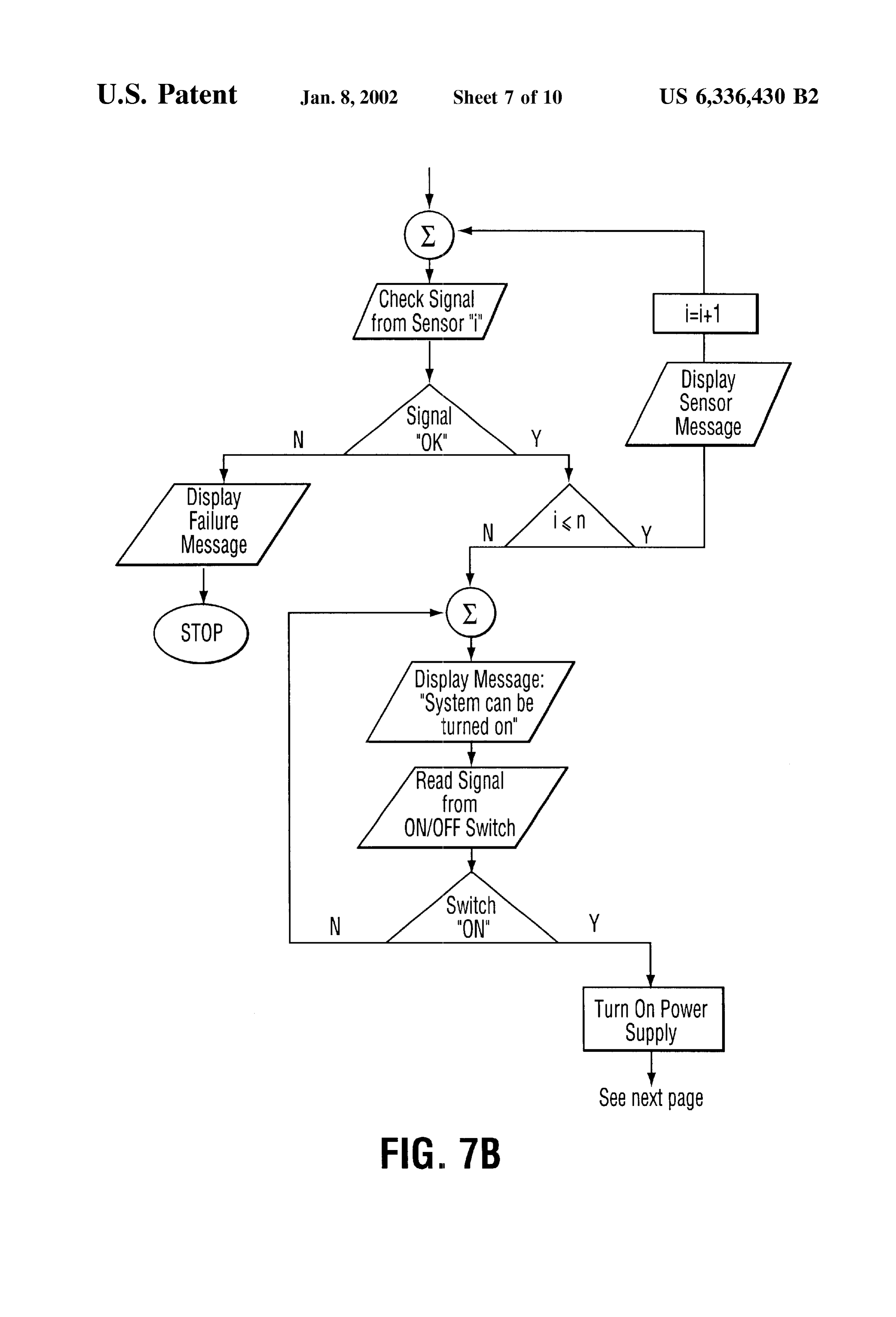
Check Signal from SenSOr "I" Display
SensOr
MeSSage
Display
Failure
MeSSage
Display MeSSage: "System can be turned On"
Read Signal from
ON/OFF SWitch Turn On POWer Supply
See next page
FIG. 7B
Page 10
Drawing sheet — no readable text.
Page 11
Drawing sheet — no readable text.
Page 12
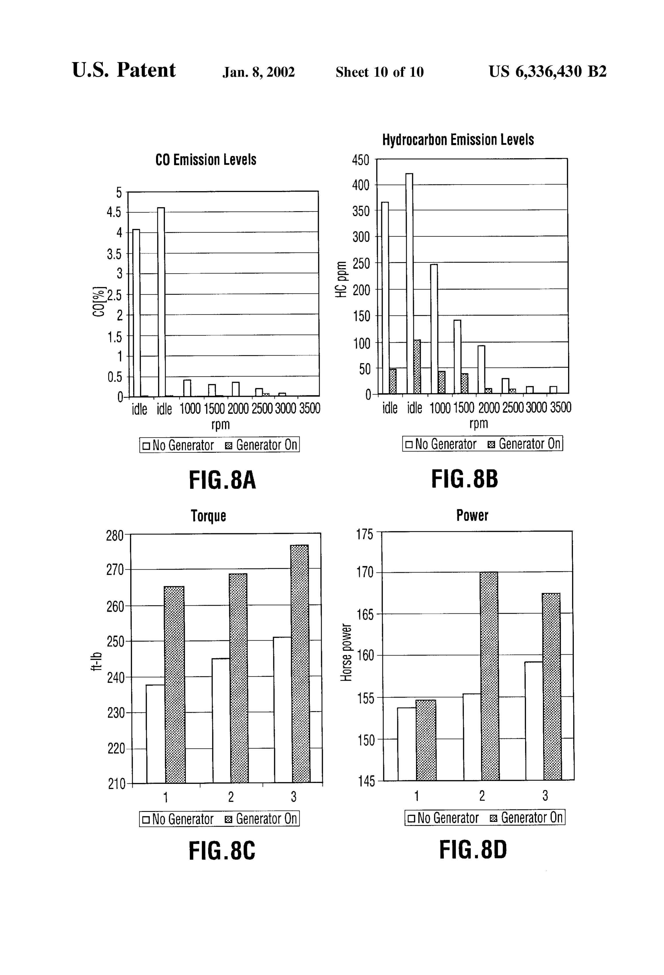
Hydrocarbon Emission levels
CO Emission Levels
ide idle OOO1500 200O250O3OOO 3500 ide idle OOO1500 200O250O3OOO 3500
oNo Generator a Generator On ONO Generator & Generator On
ONO Generator a Generator. On ONO Generator E: Generator On
Page 13
HYDROGEN GENERATING APPARATUS the engine. The hydrogen generating System of the present invention comprises an electrolysis cell for generating
FIELD OF THE INVENTION hydrogen and oxygen gases by electrolysis of an aqueous The present invention is directed to a hydrogen generating Solution, a power Source for providing electrical power to apparatus and in particular a hydrogen generating apparatus generated gasescell, the electrolysis an outlet flow means for introducing the into the intake manifold System of an for use in motor vehicles to increase the performance of the internal combustion engine, a monitoring means for moni engine of the motor vehicle. toring the operating conditions of the hydrogen generating BACKGROUND OF THE INVENTION System, and a control means connected to the monitoring means for controlling the operation of the hydrogen gener
The use of hydrogen as a Supplemental fuel in motor ating System in response to the monitoring means. vehicle engines has been proposed to increase the perfor In an aspect of the invention there is provided a controller mance of the engine. Hydrogen and oxygen when used as for controlling a hydrogen generating System for use in an part of the air/fuel mixture for the operation of the engine internal combustion engine for increasing the efficiency of has been found to increase the performance of the engine by 15 the engine and decreasing emissions from the engine. The increasing the mileage and by reducing the amount of controller comprises at least one interface means for receiv emissions from the engine. The hydrogen and oxygen may ing information on the operating conditions of the hydrogen be generated through electrolysis of an aqueous Solution generating System; at least one control means for controlling with the gases given off being mixed with the charge of fuel a parameter of the hydrogen generating System; and a logic and air Supplied to the engine. circuit connected to the interface means and control means The generation of Small quantities of hydrogen and oxy for providing instructions to the control means in response gen using an electrolysis cell with the hydrogen and oxygen to the information received from the interface means. generated then being combined with the usual air/fuel mix ture to improve the efficiency of internal combustion engines BRIEF DESCRIPTION OF THE DRAWINGS has being proposed in a number of prior patents. Some 25
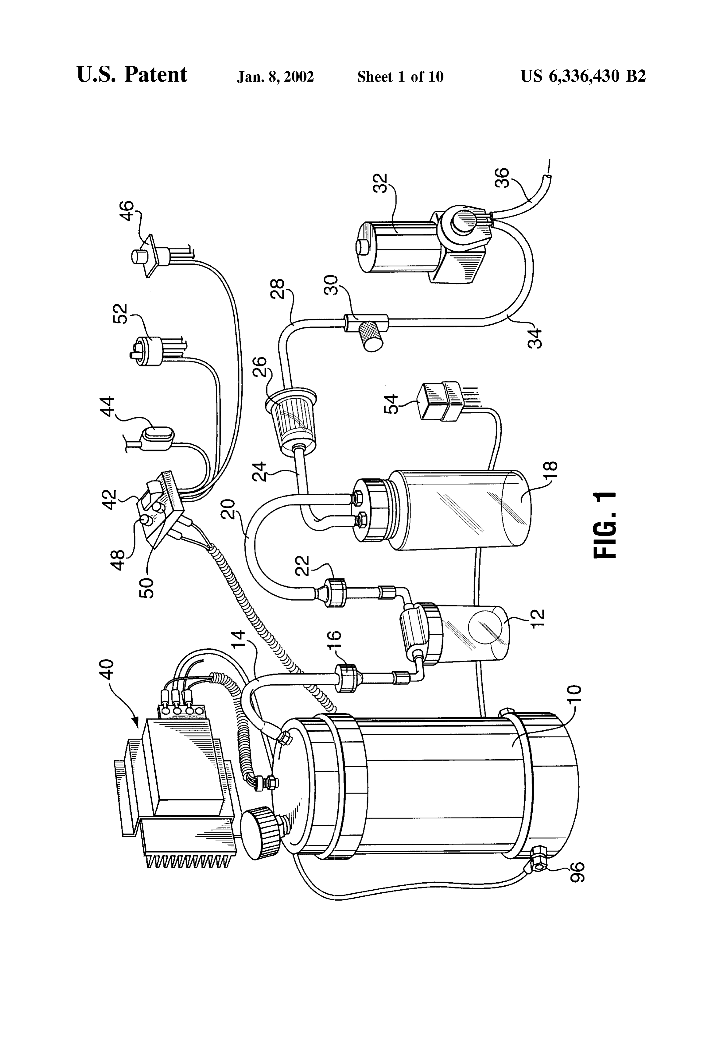
Preferred embodiments of the present invention are illus
Systems of these prior patents utilized the alternator or an trated in the attached drawings in which: auxiliary generator attached to the engine to provide the FIG. 1 is a perspective view of a preferred embodiment of electrical power for the System. the hydrogen generating System of the present invention; One example of Such a system is shown in U.S. Pat. No.
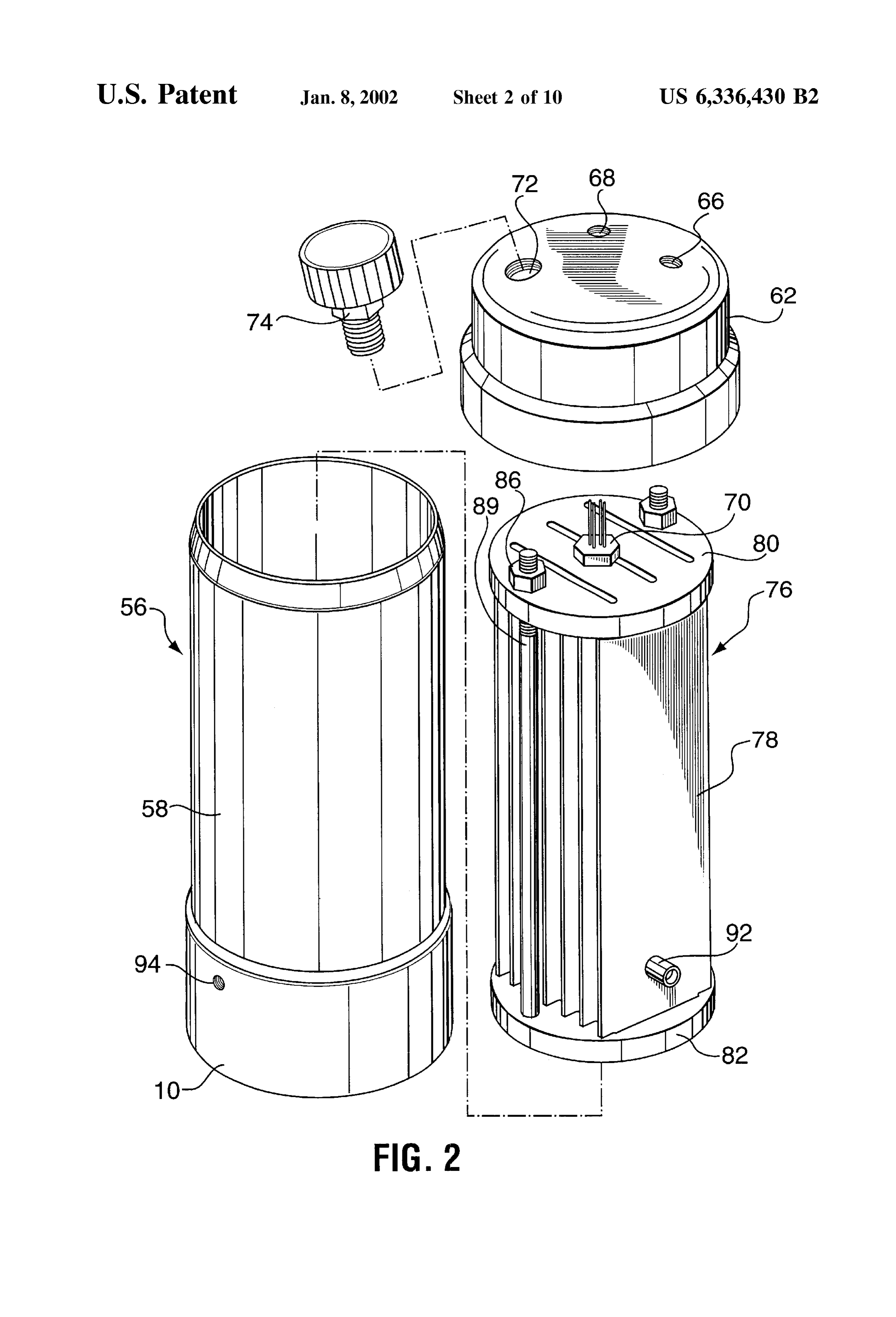
4,271,793. This patent describes an internal combustion cellFIG. of 2 is an exploded perspective view of the electrolysis the hydrogen generating System of FIG. 1;
engine having a fuel System for feeding an air/fuel mixture FIG. 3 is a side elevation view in cross section of the to the combustion chamber and an electrical generation
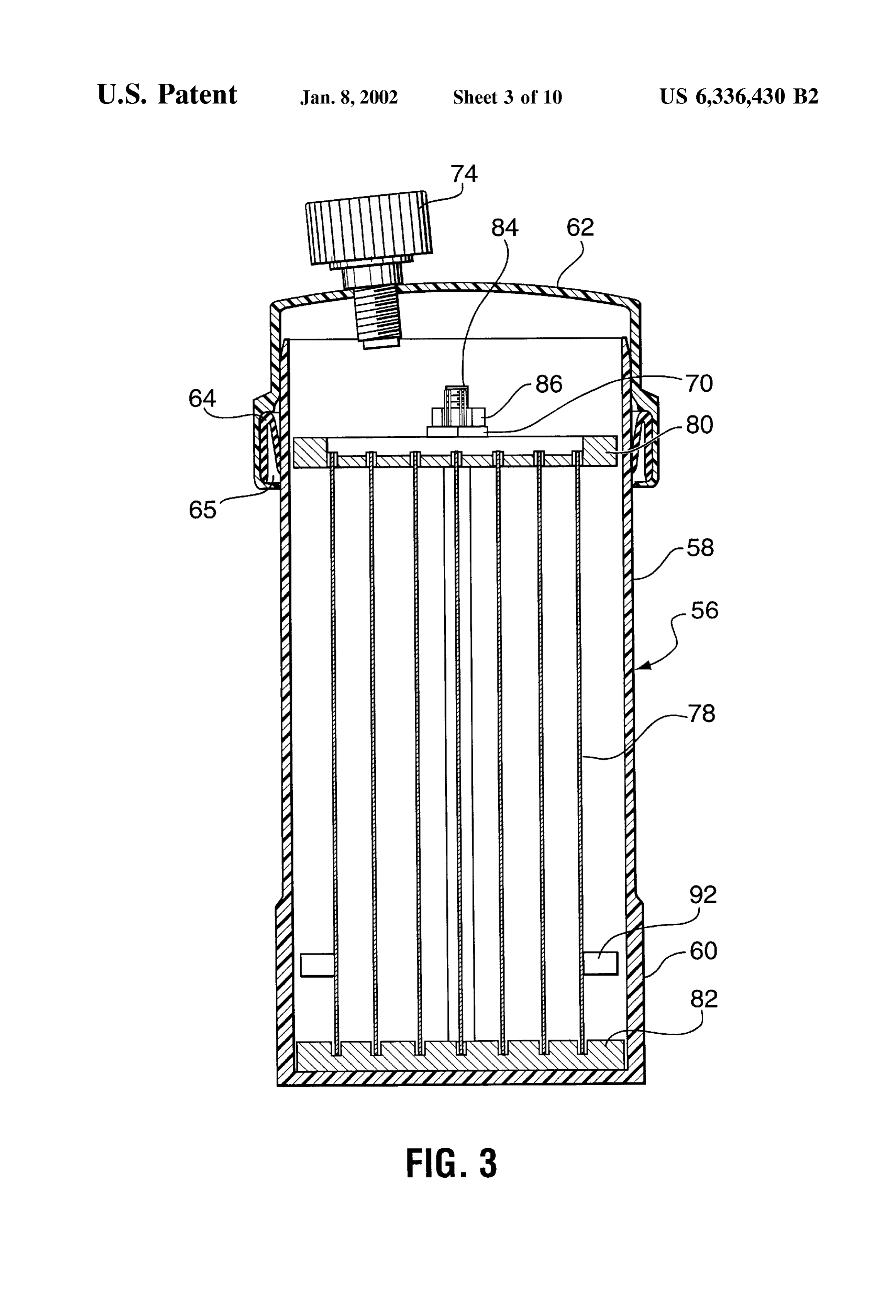
System, Such as an alternator. An electrolysis cell was electrolysis cell of FIG. 2;
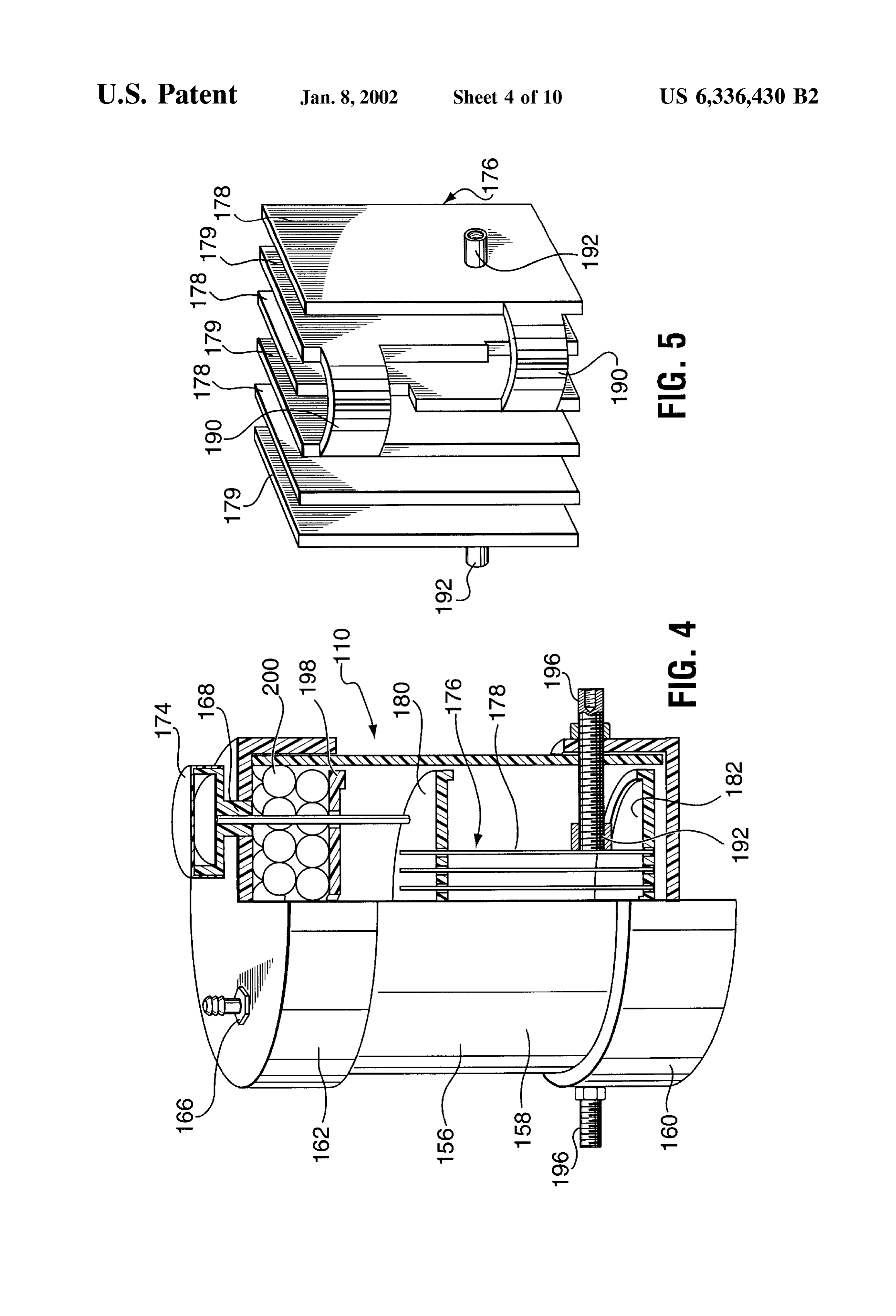
attached adjacent to the engine to generate hydrogen and FIG. 4 is a side elevation view partly in cross-section of oxygen upon the application of a Voltage between the 35 a Second embodiment of an electrolysis cell of the present cathode and the anode of the electrolysis cell. A gas feed invention;
connected the cell to the engine fuel System for feeding the FIG. 5 is a perspective view of the electrode assembly of hydrogen and oxygen to the engine combustion chambers. the electrolysis cell of FIG. 4;
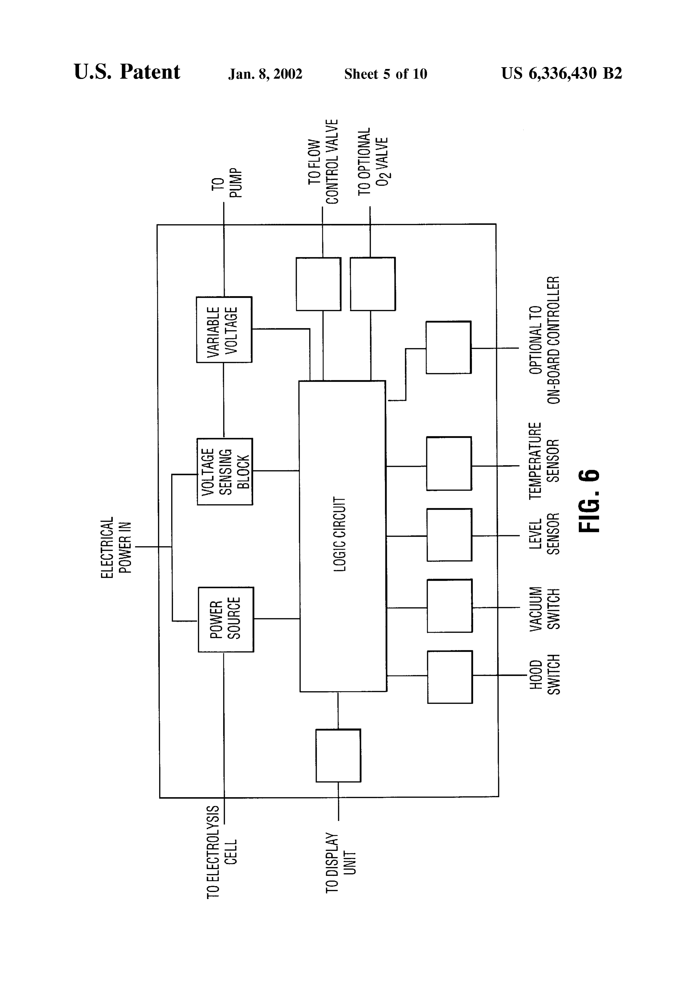
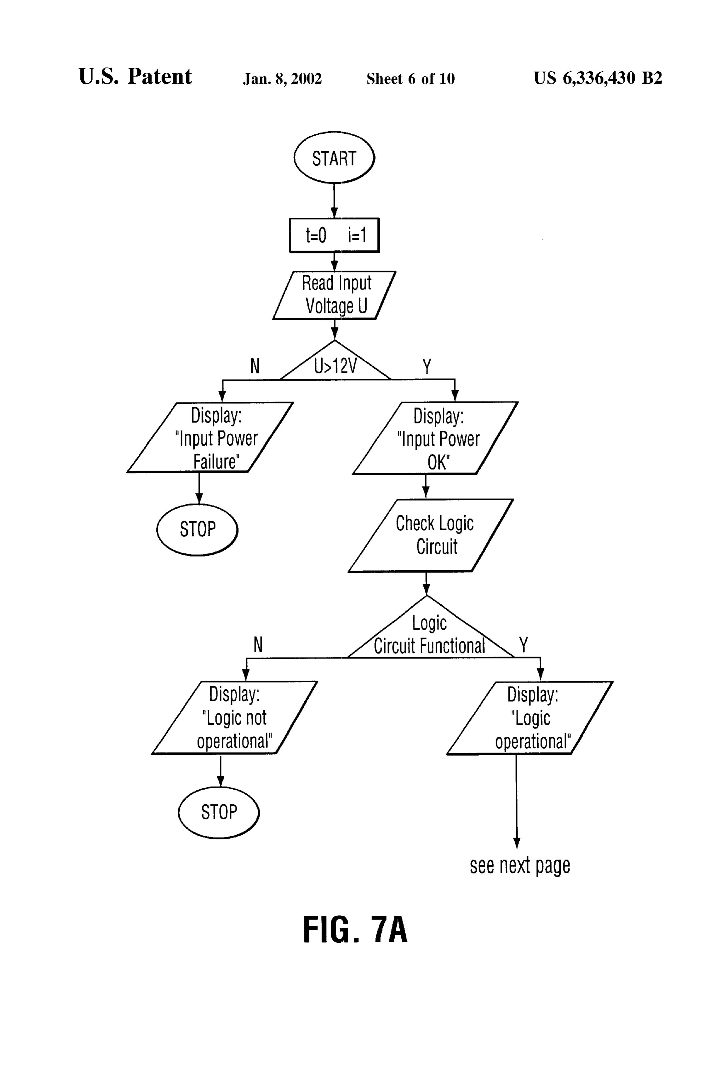
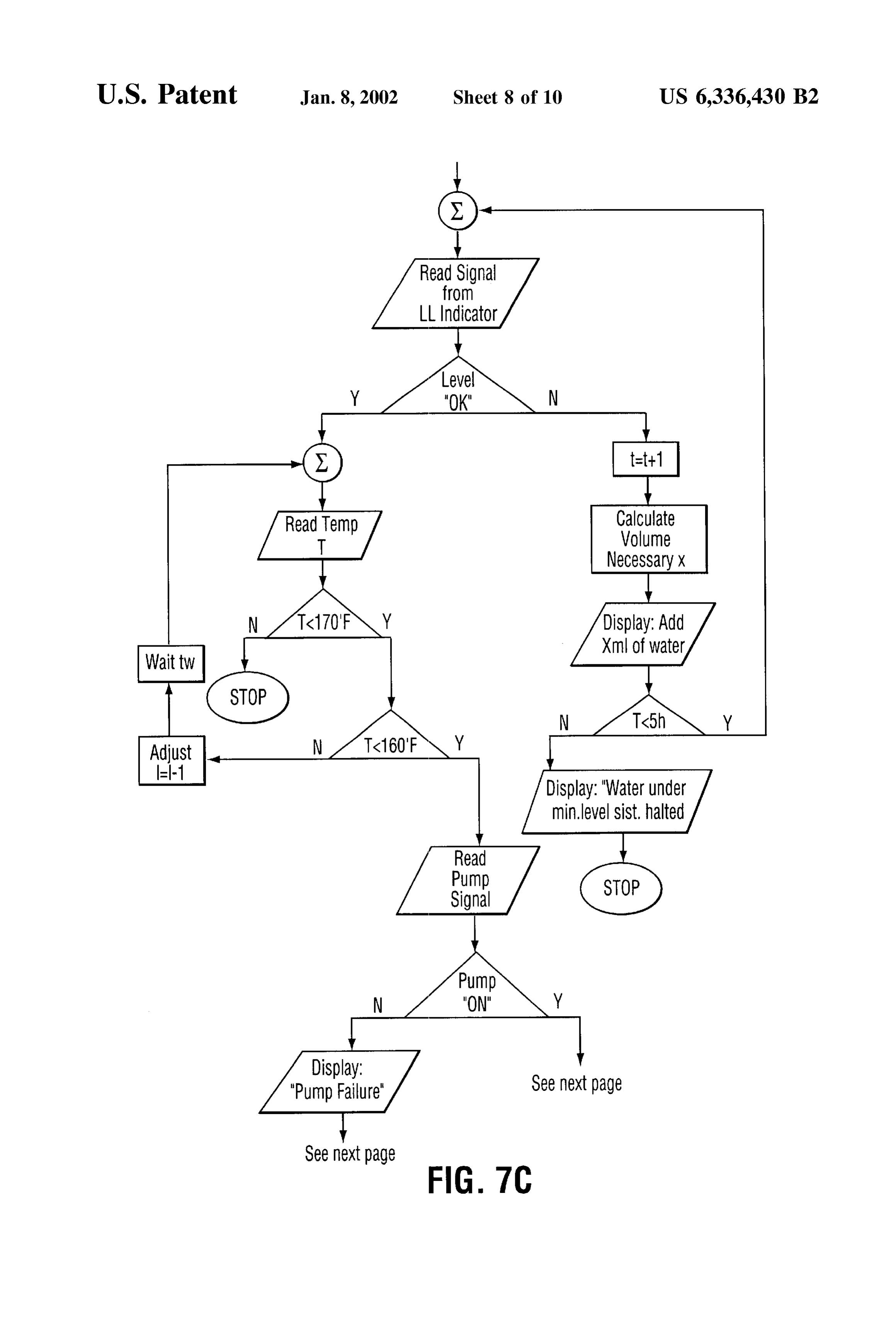
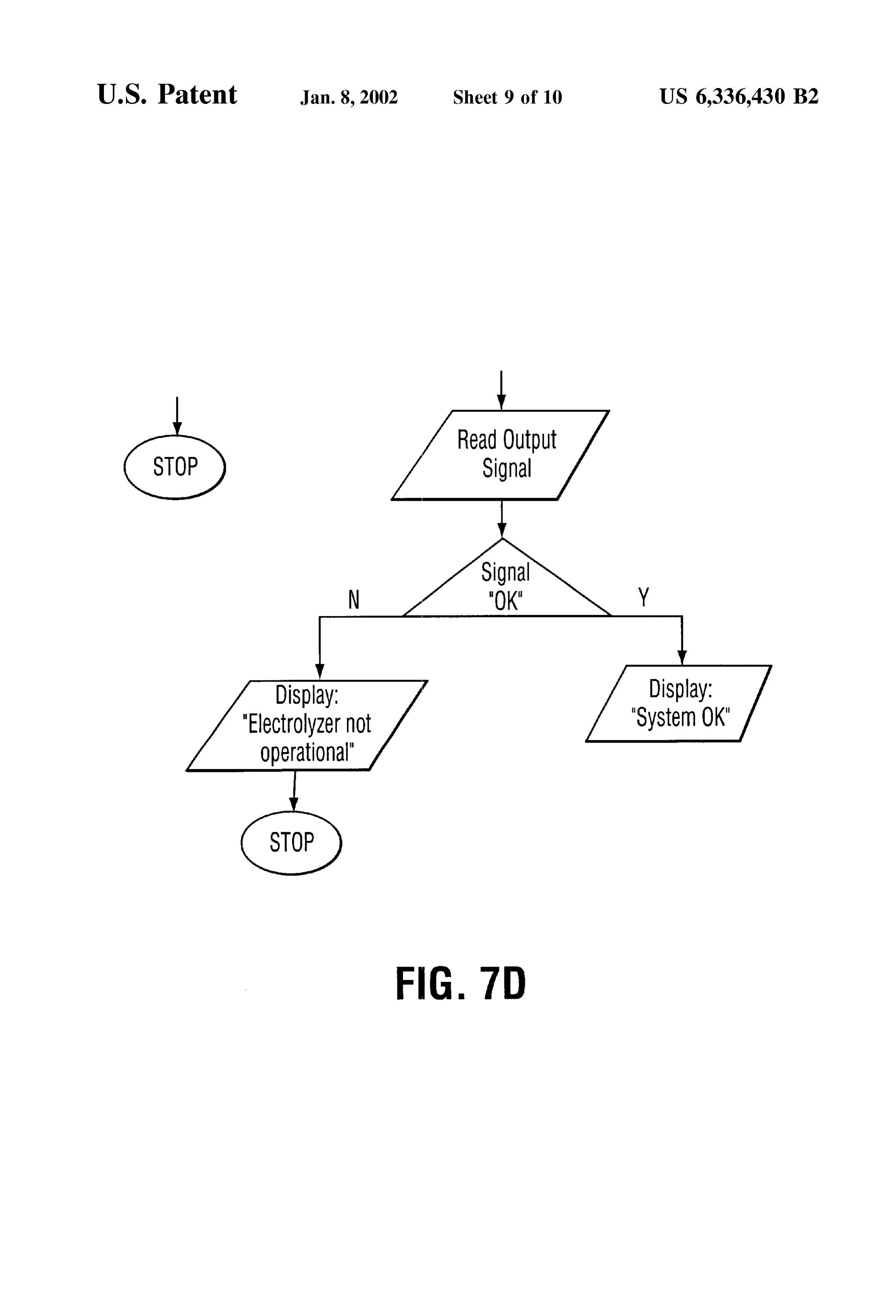
The electrolysis cell was placed under a predetermined 40 FIG. 6 is a block diagram of the electronic process pressure to prevent the electrolyte from boiling off. The cell controller of the hydrogen generating System of FIG. 1; also included a cooling System and other Safety features. FIG. 7 is a flow chart of the operation of the electronic Another electrolysis cell is disclosed in U.S. Pat. No. process controller of FIG. 6; and 5,231,954. The electrolysis cell of this patent was used for FIG. 8 is a Series of graphs illustrating the performance of generating hydrogen and oxygen gases which were added to 45 an engine with the hydrogen generating System of FIG. 1 the fuel delivery System as a Supplement to the gasoline or installed.
other hydrocarbons burned therein. The cell was designed to reduce the hazard of explosion by withdrawing the gases DETAILED DESCRIPTION OF THE through a connection with the vacuum line of the positive PREFERRED EMBODIMENT crankcase ventilation (PCV) system of the engine and by 50 A preferred embodiment of a hydrogen generating System utilizing a slip-fitted top cap for the electrolysis cell. of the present invention is illustrated in FIG. 1. The hydro A further example of an electrolysis cell for use in gen generating System includes an electrolysis cell 10 which connection with an internal combustion engine, for gener is used to generate the hydrogen and oxygen gases by ating hydrogen and oxygen gases is shown in U.S. Pat. No. electrolysis of a Suitable aqueous medium. The gases gen 5,458,095. This system utilized an electric pump to draw the 55 erated by the electrolysis cell 10 are fed through a moisture hydrogen and oxygen gases out of the cell, where the outlet trap 12 which is connected to the cell 10 by a suitable tubing Side of the pump was connected to the air intake manifold 14 which is provided with a check valve 16 to prevent the using a hose having a terminating insert. The insert was back flow of fluids into the electrolysis cell 10. The output formed from copper tubing bent at an appropriate angle to of the moisture trap 12 is connected to a bubbler 18 by insure that the hydrogen and oxygen gas outlet from the 60 means of a suitable tubing 20 which is also provided with a pump was in the Same direction as the downstream airflow check valve 22 to prevent back flow of fluids. From the in the air intake manifold. bubbler 18 the gases flow through tubing 24 to a filter 26 to SUMMARY OF THE INVENTION remove any particulate material or residual moisture in the gases. From the filter 26 the gases flow through tubing 28 to
The present invention is directed to a hydrogen generating 65 a flow control valve 30 which is adjustable to regulate the System for use in internal combustion engines for increasing flow of the gases. The output of the flow control valve 30 is the efficiency of the engine and decreasing emissions from connected to a pump 32 by tubing 34. The pump 32 pumps

Page 14
the gases to a Suitable part of the intake System of the engine. 52 will interact with the electronic process controller 40 to The gases may be injected by the pump 32 into the intake shut down the hydrogen generating System. System of the engine before the carburetor or injector by The hydrogen generating System is also provided with a connecting the tubing 36 on the outlet of the pump 32 to the relay or Solenoid 54 which is operated by the various air breather box of the intake System of the engine upstream Switches, Such as the main System Switch 42, oil preSSure from the air filter. Alternatively the gases may be injected Switch or vacuum safety switch 52 and hood trunk Switch 46 directly into the carburetor or other fuel delivery system of to provide the activation and deactivation of power to the the intake System of the engine or may be injected into the electronic process controller 40 and in turn the electrolysis intake manifold of the intake System after the carburetor or cell 10 and Vacuum pump 32 of the hydrogen generating fuel delivery System if a proper filtering System is provided. system. In a preferred embodiment the relay 54 may be AS illustrated in FIG. 1 the hydrogen generating System of incorporated into the electronic process controller 40 as the present invention includes Suitable control and feedback described in detail below.
means provided in the preferred embodiment by controller The hydrogen generating System preferably also provides 40. The controller 40 provides for control of the operation of for visual feedback to the operator of the motor vehicle. In the hydrogen generating System to provide for maximizing 15 the embodiment illustrated in FIG. 1, the main system efficiency under all conditions of operation of the engine as Switch 42 is provided with two LED displays 48 and 50, one well as monitoring the System to provide for Safe operation. LED display 48 indicating when the power is turned on to For example, one parameter of operation of the hydrogen the system, and the second LED display 50 to indicate generating System which is preferably monitored by the trouble with the system, such as for example, if the level of controller is the level of aqueous medium in the electrolysis electrolyte in the electrolysis cell 10 decreases to a level to cell 10. As described in detail below, electrolysis cell 10 is cause potential problems. Alternatively, the System could be preferably provided with a level sensor which provides provided with a display module which would include a feedback to the controller 40 on the level of aqueous alphanumeric display, which can display System messages medium in the electrolysis cell 10. If the level of the aqueous provided by the electronic process controller 40. For medium in the electrolysis cell 10 drops to a level which 25 example, as described in detail below, on operation of the would cause enough exposure of the electrodes of the cell, System after the ignition is turned on, the electronic process the cell could be damaged or production of gases becomes controller 40 could perform a System Scan for proper opera inefficient. In this situation, the controller 40 will shutdown tion of the components of the System and display various operation of the hydrogen generating System. Other param messages on the alphanumeric display.
eters of the hydrogen generating System controlled by the The hydrogen generating System of the present invention controller 40 will be explained in detail below. has a number of safety features built in. One such feature is The hydrogen generating System is also provided with a the detection of the level of electrolyte in the electrolysis cell master switch 42 which is preferably mounted in the motor 10. If the level of the electrolyte is below a specified limit, vehicle in a location easily accessible by the operator of the then a warning would be displayed to advise the operator to motor vehicle. The master Switch 42 allows the operator of 35 add fluid, preferably steam distilled water, to the cell 10. If the motor vehicle to turn the hydrogen generating System on the fluid is not added and the level is not brought up above and off as required or desired. The master Switch 42 is the limit within a Set period of time, the electronic process connected to the electrical system of the motor vehicle with controller 40 would shut the system down and indicate the a Suitably sized fuse 44. For Safety reasons, the hydrogen System failure. Another monitoring of the System could be generating System is also provided with a shutoff Switch 46 40 the temperature of the electrolyte Solution in the electrolysis which will shutdown the system when the hood of the cell 10. If the temperature on the fluid in the cell exceeds a portion of the motor vehicle where the System is located is certain limit, boiling of the electrolyte Soulution may occur raised. Thus if the hydrogen generating System is located in or the cell may be damaged. The Safety temperature limit is the engine compartment the shutoff Switch 46 would be Set according to many factors, Such as, cell design and the mounted Such that raising the hood of the engine compart 45 nature of the electrolyte solution. Preferably with the design ment will cause the Switch 46 to open and shutdown the of the preferred embodiment described below, the tempera hydrogen generating System. Similarly if the hydrogen gen ture of the electrolyte in the electrolysis cell 10 should not erating System is mounted in the trunk compartment the exceed 160 F. In order to monitor the temperature in the shutoff Switch would be located such that raising the hood of cell, a temperature probe may be provided to provide a the trunk compartment will shut off operation of the System. 50 feedback on the electrolyte solution temperature. If the The hydrogen generating System of the present invention temperature increases, the electronic process controller 40 also includes a means of determining that the engine is could limit the current to the cell 10 to reduce the amount of running so that if power is applied to the controller 40 but electrolysis taking place, and there by reduce the tempera the engine is not actually running, no electrolysis will take ture of the cell 10. Should the temperature not reduce or place. The means to determine that the engine is running 55 continue to rise, the electronic process controller 40 could could be a Sensor monitoring one or more of the engine shut down the electrolysis cell 10 by disrupting the power conditions when the engine is operating. For example, a being provided to the cell 10 and restore functioning of the Sensor could be used to monitor vacuum or oil pressure System if the appropriate temperature is attained. which is present in an operating engine. Preferably, a The hydrogen generating System of the present invention Vacuum Safety Switch 52 is utilized to insure that the engine 60 also monitors the engine vacuum through the vacuum Safety is running. The vacuum safety switch 52 monitors the Switch 52, as described above. If the engine vacuum drops Vacuum, preferably from a different Source than the vacuum below a preset level, then the electronic process controller intake line to the engine. While there are numerous Sources 40 will shut down the system. In addition, as the preferred of vacuum on the engine, the preferred Source for monitor embodiment of the present invention utilizes the vacuum ing of engine vacuum is the heater vacuum line. The vacuum 65 pump 32, the process controller 40 could also monitor the safety switch 52 is adjusted such that should the level of operation of the vacuum pump 32, particularly with respect engine Vacuum drop below a preset level, the Safety Switch to the electrical power being provided to the pump 32.
Page 15
S 6
Should the electric circuit to the pump 32 be interrupted, Figures, electrode assembly 76 has a Series of electrode then the electronic process controller 40 will shut down the plates 78 mounted between a top plate 80 and a bottom System by cutting the electrical power Supplied to the retainer plate 82 made of durable non-reactive materials electrolysis cell 10. In addition, should the gas supply line of compatible with the electrolyte solution. The electrode the gases generated by the electrolysis cell 10 become assembly 76 is held together by Suitable bolts 84 and nuts 86. blocked Such that the pressure in the line increases, then the The electrodes 78 are provided as a series of bipolar elec electronic process controller 40 will sense that through the trode between an outside anode and cathode. The outside pump circuit and shut down the power Supply. cathode and anode electrode plates 78 are provided with an The details of a preferred embodiment of an electrolysis adapter 92 for electrical connection to the positive and cell 10 of the present invention are shown in FIGS. 2 and 3. negative Supply from the motor Vehicle electrical System. Electrolysis cell 10, preferably has a cylindrical shaped case When the electrode assembly 76 is placed within the case 56, constructed of a Suitable material which would be inert 56, adapters 92 are in alignment with openings 94 in the case to the electrolyte solution and would not be affected by the 56 for connection of a terminal 96.
Voltages or temperatures encountered in the electrolysis cell While the electrode assembly 76, as illustrated in the 10. The case 56 should also preferably have a co-efficient of 15 Figures, is shown as a Series of electrode plates, other expansion which does not cause significant expansion of the configurations of the electrode assembly are possible. Thus, dimensions of the cell 10 under the operating conditions of for example, the electrode assembly could comprise a Series the hydrogen generating System. Preferably, the case 56 of of bar electrodes arranged in a Suitable array. Alternatively, the electrolysis cell 10 is a polyvinyl chloride. While the the electrode assembly could be a plurality of concentric case 56 may be provided as a one-piece mold, it is preferred circular electrodes. The electrode assembly 76 provides for that for uniformity, the case 56 be in two sections, the a multi-cell bipolar electrode assembly for increased effi sidewall 58 and the base 60 which are PVC welded to give ciency of the electrolysis reaction in the electrolysis cell 10. the characteristics of a one-piece Structure. The materials from which the electrode assembly 76 is The electrolysis cell 10 is preferably provided with a cap constructed are selected to minimize the effects of different 62 which has a slight dome shape to provide a gas accu 25 coefficients of expansion of the materials, withstand Strong mulation Zone. The junction between the sidewall 58 of the corrosive action of the electrolyte Solution and provide case 56 of the electrolysis cell 10 and the cap 62 is sealed by effective and efficient electrolysis process. Thus, preferably, a U-shaped Sealing member 64 of a Suitable elastomeric the electrode plates 78 are a Suitable Stainless Steel material, material which is resistant to the effects of the electrolyte most preferably nickel plated StainleSS Steel, and the top solution. The U-shaped seal 64 is placed within a groove 65 plate 80 and bottom plate 82 are polypropylene. Preferably, located in the interior of the cap 62. The U-shaped seal is the bolt 84 and nut 86 are also a polypropylene material. provided with a generally vertical Outer wall of a height and The fill plug can be a bi-directional relief valve which, in width to fit securely within the groove in the cap. The seal addition to providing for relief of the pressure in the interior is further provided with top Surface connecting the inner and of the cell should the pressure increase, is also utilized for outer walls. The inner wall of the seal has an inwardly 35 air intake into the electrolysis cell 10. AS the gas generated canting Sealing Surface and is preferably provided with a within the cell 10 by electrolysis is being drawn off by the lower Surface region which cants inwardly at a greater angle vacuum pump 32, Some air is allowed to enter the cell 10 than the upper Surface region. It has been found that a through the filler plug 74 to balance the pressure within the U-shaped seal 64 as described provides for better sealing of interior of the cell 10. The air entering the cell also provides the electrolysis cell 10 than a typical O-ring type seal. With 40 a Secondary benefit of aiding in cooling of the electrolysis the orientation of the U-shaped Seal as described, efficient cell. The filler plug 74 is preferably provided with a suitable Sealing under vacuum is achieved while also providing for filter material to filter the incoming air. ease of release of pressure or cap under conditions of exceSS The electrolyte solution utilized within the electrolysis preSSure. If a vacuum is present in the gas accumulation cell 10, is preferably a basic aqueous Solution to provide for Zone, the vacuum will draw the lower Surface region of the 45 increased efficiency of the electrolysis reaction. Preferably, Sealing Surface of the inner wall against the outer Sidewall the Solution is also adjusted to remain in Solution form and Surface of the case. If the pressure in the gas accumulation not freeze at extremely low temperatures, down to -40 or Zone increases, the exceSS pressure will bias the lower more. Most preferably, the electrolyte solution is a 20 to Surface region of the Sealing Surface of the inner wall away 30% KOH solution. The bubbler Solution within the bubbler from the outer Sidewall Surface of the case, allowing the 50 18 is preferably a silicate free solution with a viscosity to exceSS pressure to be released. allow the bubbles to break to the surface quickly and not The cap 62 is provided with a first opening 66 for an outlet accumulate within the Solution.
of the electrolysis cell 10 to which the tubing 14 is con A second embodiment of an electrolysis cell 110 of the nected. Cap 62 is provided with a second opening 68 for present invention is illustrated in FIGS. 4 and 5. Similar to electrical connection of the level and temperature Sensors 55 the first embodiment, electrolysis cell 110, preferably has a 70. A third opening 72 is provided in the cap 62 for receiving cylindrical shaped case 156, constructed of a Suitable mate a fill plug 74. Fill plug 74 is removable to allow the addition rial inert to the electrolyte solution, not affected by the of distilled water or electrolyte solution to the cell as the Voltages or temperatures encountered in the electrolysis cell level of fluid in the electrolysis cell 10 decreases. Preferably, 110 and having a co-efficient of expansion which does not fill plug 74 also incorporates a preSSure release mechanism 60 cause significant expansion of the dimensions of the cell 110 to provide for relief of the pressure within the cell 10 should under the operating conditions of the hydrogen generating the interior pressure increase beyond a set limit. The fill plug system. Preferably, the case 156 of the electrolysis cell 110 also functions as a breather which filters the air entering the is a polyvinyl chloride provided in two Sections, the Sidewall electrolysis cell and limits the air intake via a preSS fitted 158 and the base 160 which are PVC welded to give the orifice designed to meet desired flow requirements. 65 characteristics of a one-piece structure. The electrolysis cell 10 is provided with an electrode The electrolysis cell 110 is provided with a welded on cap assembly 76. In the preferred embodiment illustrated in the 162. The cap 162 is provided with a first opening for an
Page 16
outlet of the electrolysis cell 110 to which a fitting 166 for A preferred embodiment of the controller 40 of the the tubing is connected. Cap 162 is provided with a Second present invention is illustrated in block diagram in FIG. 6. opening 168 for receiving a fill plug 174. Fill plug 174 is The controller 40 is provided with a logic circuitry 100 to removable to allow the addition of distilled water or elec control the operation of the controller. Logic circuitry 100 trolyte solution to the cell as the level of fluid in the includes the programmed instructions for operation of the electrolysis cell 110 decreases. Preferably, fill plug 174 also controller preferably stored within a non-volatile memory incorporates a pressure release mechanism to provide for which may be part of the logic circuitry 100 or may be relief of the pressure within the cell 110 should the interior provided as a separate component of the controller 40. preSSure increase beyond a Set limit. Controller 40 also includes suitable interfaces for interfacing The electrolysis cell 110 is provided with an electrode 1O the logic circuitry 100 to the sensors and Switches of the assembly 176. In the preferred embodiment illustrated in hydrogen generating System. Depending upon the nature of FIGS. 4 and 5, electrode assembly 176 has a pair of the Sensor or Switch, the interface may be a simple interface electrode plates 178 and 179 mounted between a top plate to communicate to the logic circuitry that a signal is or is not 180 and a bottom retainer plate 182 made of durable present from the Sensor or Switch or the interface may non-reactive materials compatible with the electrolyte Solu 15 provide an indication of the Signal level from the Sensor or tion. The electrode assembly 176 is held together by Suitable Switch.
bolts and nuts. The electrodes are provided as the combi For example, Sensors which provide a digital output Such nation of an outside anode 178 and a cathode 179 and a series of alternating parallel anodes 178 and cathodes 179. directly as a TTL level sensor the output of the sensor could be The individual anodes 178 and cathodes 179 are joined to connected to the logic circuitry. The Signal could be gether by means of bridging straps 190 The outside cathode converted into a “0” or “1” logic signal. The level of the fluid 179 and anode electrode plates 178 are provided with an inside the electrolysis cell is then considered to be “full” or adapter 192 to which a terminal 196 is attached for electrical “not full”. When a “not full signal is present, the logic connection to the positive and negative Supply from the circuit will extrapolate the results to estimate the actual level motor vehicle electrical system. When the electrode assem of electrolyte inside the cell as described below. In these bly 176 is placed within the case 156, adapters 192 are in 25 circumstances, the interface is preferably an analog/digital alignment with openings 194 in the case 156 for connection converter which converts the level of the signal from the of a terminal 196. Sensor to a digital word which may then be processed by the The electrode assembly 176 provides for a mono-cell logic circuitry 100. The non-volatile memory would include monopolar electrode assembly for increased efficiency of the digital words corresponding to predetermined levels for the electrolysis reaction in the electrolysis cell 110. The mate Signals from the various Sensors to enable the logic circuitry rials from which the electrode assembly 176 is constructed to determine if the Signal is within acceptable ranges and are selected to minimize the effects of different coefficients hence whether the component of the hydrogen generating of expansion of the materials, withstand strong corrosive System is operating within an acceptable range. action of the electrolyte Solution and provide effective and The controller 40 is also provided with a power circuit to efficient electrolysis process. Thus, preferably, the electrode 35 regulate the electrical power provided to the electrolysis cell. plates 178 are a suitable stainless steel material, most The controller 40 is connected to the electrical system of the preferably nickel plated stainless steel, and the top plate 180 motor Vehicle to provide a Source of electrical power for and bottom plate 182 are polypropylene. Preferably, the bolt operation of the hydrogen generating System. A voltage and nut are also a polypropylene material. While the elec Sensing block is connected co the electrical power input to trode assembly 176, as illustrated in FIGS. 4 and 5, is shown 40 allow the logic circuit to measure and possibly compare as a pair of electrode plates, Similar to the first embodiment, Voltage drops. The power circuit has an output to provide other configurations of the electrode assembly are possible. electrical power to the electrolysis cell at the proper level, The electrode assembly 176 of the electrolysis cell 110 of the level of electrical power being under the control of the FIG. 4 is of a reduced height compared to the assembly of logic circuitry which interfaces with the power circuit. The the cell 10 of FIG. 1. This reduced height provides for a 45 amount of power Supplied to the electrolysis cell controls the larger electrolyte capacity and allows the cell 110 to operate electrolysis reaction. AS the amount of power being Supplied for longer periods of time before fresh fluid must be added is controlled by the controller, the controller can regulate the to the cell. This also provides for a larger Safety margin as electrolysis reaction in response to monitored conditions the operator is given a longer period of warning as the including engine demand.
electrolyte fluid level is dropping in the cell 110. The 50 The controller may optionally be provided with variable electrolysis 110 cell of FIG. 4 is provided with a separator power regulator for the pump to enable the logic circuitry to plate 198 to Separate the electrolyte containing region from regulate the electrical power provided to the pump, and the gas accumulation Zone. To reduce the amount of gases hence the flow rate of the pump, if a pump included as part which are retained within the gas accumulation Zone, the gas of the System. In addition in those Systems which utilize a accumulation Zone is filled with inert plastic spheres 200 55 variable flow control valve, the controller may be able to Such that the potential Volume for the accumulation of gases control the flow setting of the flow by means of and interface is reduced. This in turn reducces the potential for danger between the logic circuitry and the flow control valve. should there be any malfuncctions in the System. An addi Another option available would be in those systems in which tional benefit of the balls is to act as a mechanical barrier for the output gases of the electrolysis cell are separated before airborne liquid particles contained in generated gases. 60 introduction into the intake system of the motor vehicle. In Similar to the first embodiment, the electrolyte solution those Situations, the amount of one or both of the gases in the utilized within the electrolysis cell 110, is preferably a basic mixture being provided to the engine could be regulated. aqueous Solution to provide for increased efficiency of the Preferably, the mixture of gases would be control by con electrolysis reaction. Preferably, the Solution is also adjusted trolling the amount of oxygen in the mixture. This could be to remain in Solution form and not freeze at extremely low 65 accomplished by providing an oxygen valve which would be temperatures, down to -40 or more. Most preferably, the controlled by the logic circuitry through an interface to electrolyte solution is a 20 to 30% KOH solution. regulate the amount of oxygen in the mixture. The exceSS
Page 17
oxygen produced by the electrolysis cell could be vented to trical System of the motor vehicle. So long as the electrical the external environment. power were below the operational level a message would be Many later model motor vehicles utilize on-board con displayed to indicate this.
trollers or computers to control various parameters of the If the level of electrical power available for the system is operation of the engine of the motor vehicle particularly acceptable, then the controller displays that the level is with respect to controlling exhaust gas pollution. For acceptable and proceeds to check the logic circuitry. If the example, many vehicles are provided with Sensors to deter logic circuitry is not functioning properly, then the controller mine the makeup of the exhaust gases or the fuel/air mixture will cause a message to be displayed and will Stop operation being introduced into the engine. The on-board controller is of the hydrogen generating System. If the logic circuitry is capable of controlling the fuel/air mixture in response to functioning properly, then this will be displayed and the monitored conditions to attempt to minimize as much as controller proceeds to test the Sensors employed as moni possible the amount of pollutants in the exhaust gas of the toring means for monitoring the main Safety features of the engine. The controller 40 of the present invention may be hydrogen generating System. Such Safety features include provided with an interface for the on-board controller to the hood open Switch and vacuum level switch. The con receive Signals from the on-board controller as well as to 15 troller could also test at least Some of the Sensors used to provide Signals to the on-board controller. For example, as monitor the operating conditions at time Such as the level the gases being generated by the electrolysis cell and intro sensor to monitor the level of solution in the electrolysis cell duced into the intake System of the engine would be high in if desired.
oxygen content, an on-board controller that was monitoring oxygen content of either the fuel/air mixture or the exhaust theThe controller has stored in memory the identification of various Sensors and includes an indication of the number gas may determine that the fuel/air mixture is too lean and of Such Sensors used in the System. The controller uses a may attempt to regulate the mixture to make it richer. In this
Situation, the controller 40 could provide a signal to the count up or count down function to test the Sensors in on-board controller to tell it that the high oxygen level is Sequence, then the controller testing each Sensor in Sequence and counting up or down until either the number equal to from the electrolysis reaction and not to adjust the richneSS 25 the total number of Sensors or the counter reaches Zero. of the mixture. The interface between the controller 40 and the on-board controller could also be utilized to monitor Preferably, the controller uses a count up counter with the engine conditions to enable the controller 40 to control the total number of Sensors Stored in memory. AS illustrated in electrolysis reaction depending upon engine conditions and FIG. 7, the controller checks the signal from the first sensor, and if the Signal is acceptable, displays the message, incre demand. Thus under high load conditions the rate of elec ments the counter and test the next Sensor. This is repeated trolysis could be increased to increase the efficiency of the engine under high demand typical combustion conditions. In until all of the Sensors have been tested and found accept able. Should any of the Sensors not be functioning properly, idle conditions the combustion would require different the controller displays the failure message and stops opera hydrogen amounts. tion of the System.
The controller 40 is also provided with an interface for a 35 display module which is preferably mounted in the cab of hydrogenthegenerating
Once controller has tested all of the sensors, the
System is ready for power up. The the motor vehicle. Display module is as described above capable of displaying at least alphanumeric messages to controller could display a message to prompt the user to provide the operator and diagnostic technician of the motor power on the main hydrogen generating System. The con vehicle with an indication of the operation of the System and 40 troller would then wait until a signal is received indicating a warning of any problems which may arise in the System. that the main power Switch has been turned on. The display module may also have the capability of dis Alternatively, the controller could automatically proceed playing graphical images to graphically display the opera with power up of the System once the main Safety Sensors tion of the system and any problem areas. This would be have passed the functional test or a manual overide could be particularly useful with those controllers which include an 45 instigated by the operator of the System. interface with an on-board controller used in later models Once the Signal for main power up is received by the motor vehicles. controller, the controller turns on the power Supply and then The operation of a preferred embodiment of the controller proceeds to monitor the Sensors employed as monitoring of the present invention is illustrated in the flow chart of means to monitor the operating conditions of the hydrogen FIG. 7. On startup the controller resets certain of the 50 generating System. These Sensors include the level Sensor variables Stored in memory for example by Setting the and temperature Sensor for monitoring the and then proceeds variable for the sensor number to 1 and, if desired, read to monitor the Sensors employed as monitoring means to values from the non-volitile memory. The controller then monitor the operating conditions of the hydrogen generating reads the level electrical power available for the system System. These Sensors include the level Sensor and tempera preferably by reading the level of the input Voltage to 55 ture Sensor for monitoring the level and temperature of the determine if the level of the voltage is sufficient for proper Solution in the electrolysis cell and for those Systems using operation of the system. While the level of voltage is the a pump to introduce the gases into the engine intake System, Simplest to monitor, other indicators of electrical power a pump SenSOr.
including current could also be used. If the Voltage level is The controller reads the signal from the level sensor to below a preset level, typically about 12 volts, then the 60 determine the level of Solution in the electrolysis cell. If the controller will display a System failure message Such as level is acceptable, the controller proceeds to read the Signal shown in the Figure on the display and Stop operation of the from the next Sensor monitoring the operating conditions of System. If desired, the controller could be programmed to the hydrogen generating System. If the level of Solution in recheck the electrical power level on a preprogrammed the electrolysis cell is below acceptable levels, then the interval rather than merely stopping the System. This could 65 controller will calculate the amount of distilled or de-ionized be useful if the System was running on an auxiliary power water required to be added to the cell to bring the level up Source which may have to be recharged by the main elec to within an acceptable range. The calculation is based upon
Page 18
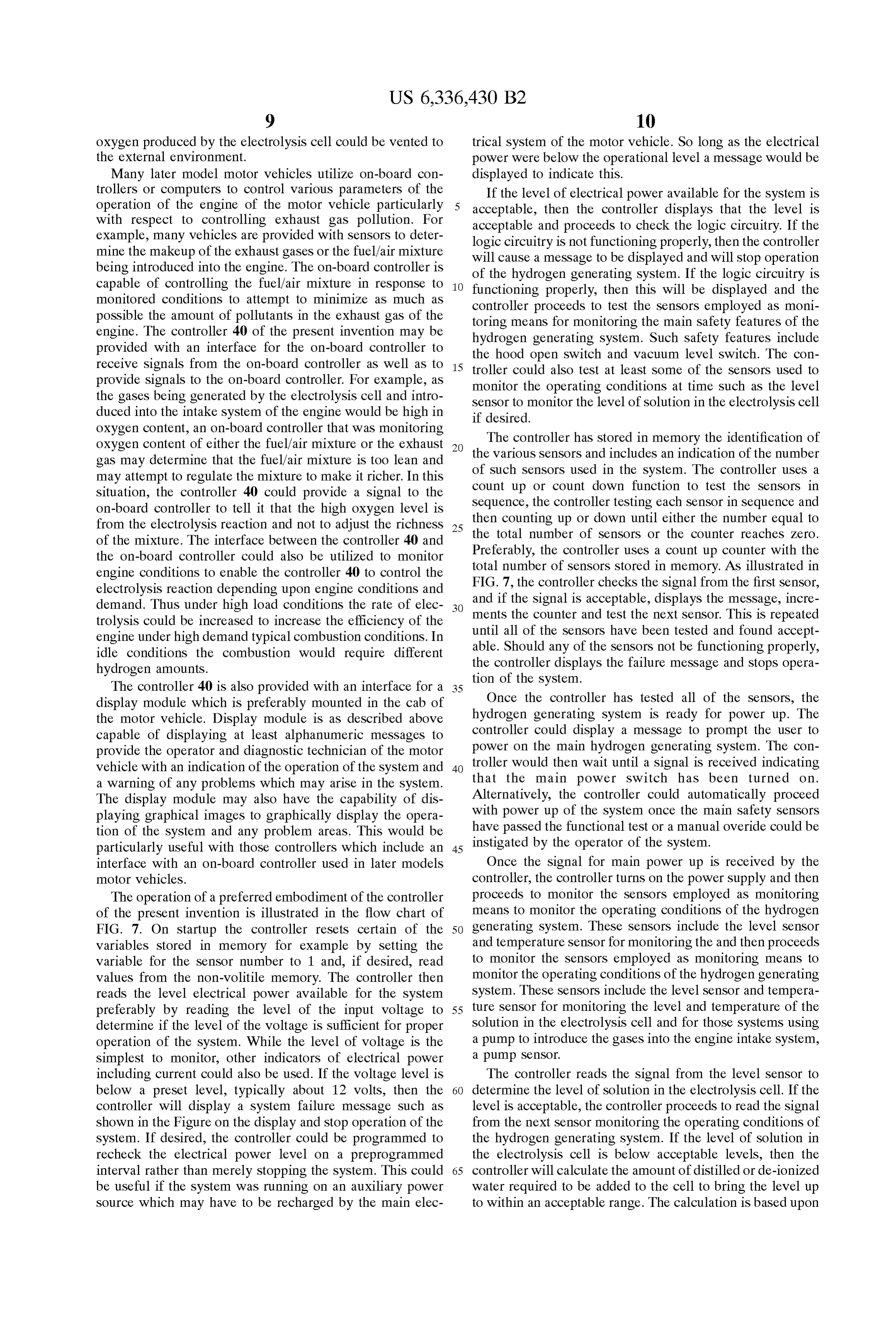
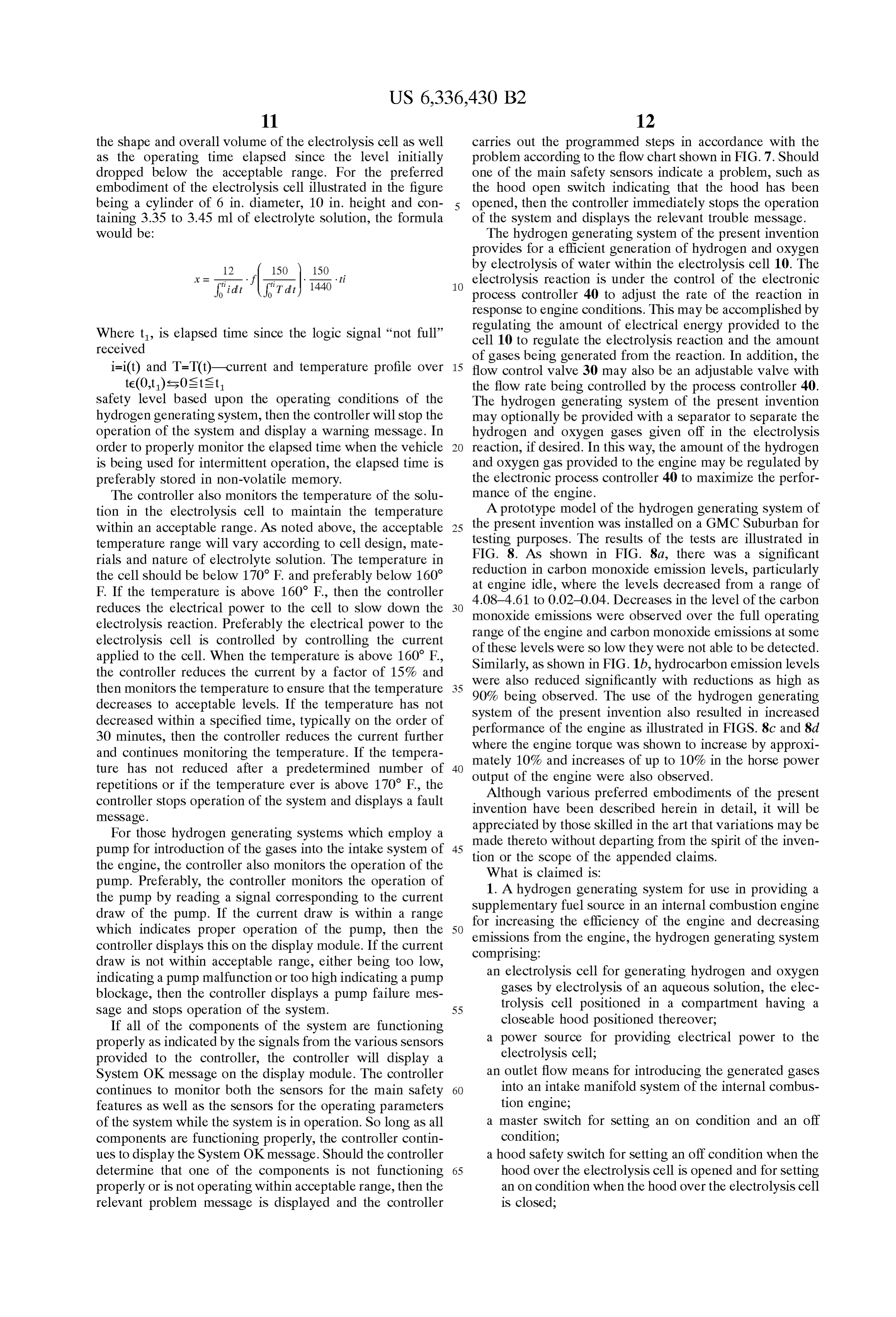
the shape and overall volume of the electrolysis cell as well carries out the programmed Steps in accordance with the as the operating time elapsed since the level initially problem according to the flow chart shown in FIG. 7. Should dropped below the acceptable range. For the preferred one of the main Safety Sensors indicate a problem, Such as embodiment of the electrolysis cell illustrated in the figure the hood open Switch indicating that the hood has been being a cylinder of 6 in. diameter, 10 in. height and con opened, then the controller immediately stops the operation taining 3.35 to 3.45 ml of electrolyte solution, the formula of the System and displays the relevant trouble message. would be: The hydrogen generating System of the present invention provides for a efficient generation of hydrogen and oxygen 150 150 by electrolysis of water within the electrolysis cell 10. The
ti electrolysis reaction is under the control of the electronic process controller 40 to adjust the rate of the reaction in response to engine conditions. This may be accomplished by
Where t, is elapsed time Since the logic Signal “not full” regulating the amount of electrical energy provided to the cell 10 to regulate the electrolysis reaction and the amount received of gases being generated from the reaction. In addition, the i=i(t) and T=T(t)-current and temperature profile over 15 flow control valve 30 may also be an adjustable valve with te(0,t) es0s tst the flow rate being controlled by the process controller 40. Safety level based upon the operating conditions of the The hydrogen generating System of the present invention hydrogen generating System, then the controller will Stop the may optionally be provided with a separator to Separate the operation of the System and display a warning message. In hydrogen and oxygen gases given off in the electrolysis order to properly monitor the elapsed time when the vehicle reaction, if desired. In this way, the amount of the hydrogen is being used for intermittent operation, the elapsed time is and oxygen gas provided to the engine may be regulated by preferably Stored in non-volatile memory. the electronic process controller 40 to maximize the perfor The controller also monitors the temperature of the solu mance of the engine.
tion in the electrolysis cell to maintain the temperature A prototype model of the hydrogen generating System of within an acceptable range. AS noted above, the acceptable 25 the present invention was installed on a GMC Suburban for temperature range will vary according to cell design, mate testing purposes. The results of the tests are illustrated in rials and nature of electrolyte Solution. The temperature in FIG. 8. As shown in FIG. 8a, there was a significant the cell should be below 170 F. and preferably below 160° reduction in carbon monoxide emission levels, particularly at engine idle, where the levels decreased from a range of
F. If the temperature is above 160 F., then the controller 4.08-4.61 to 0.02-0.04. Decreases in the level of the carbon reduces the electrical power to the cell to slow down the monoxide emissions were observed over the full operating electrolysis reaction. Preferably the electrical power to the range of the engine and carbon monoxide emissions at Some electrolysis cell is controlled by controlling the current of these levels were so low they were not able to be detected. applied to the cell. When the temperature is above 160 F., Similarly, as shown in FIG.1b, hydrocarbon emission levels the controller reduces the current by a factor of 15% and were also reduced significantly with reductions as high as then monitors the temperature to ensure that the temperature 35 90% being observed. The use of the hydrogen generating decreases to acceptable levels. If the temperature has not System of the decreased within a specified time, typically on the order of performance ofpresent the invention also resulted in increased engine as illustrated in FIGS. 8c and 8d 30 minutes, then the controller reduces the current further and continues monitoring the temperature. If the tempera where the engine torque was shown to increase by approxi ture has not reduced after a predetermined number of 40 mately of 10% and increases of up to 10% in the horse power repetitions or if the temperature ever is above 170 F., the output Although the engine were also observed.
various preferred embodiments of the present controller Stops operation of the System and displays a fault invention have been described herein in detail, it will be meSSage.
For those hydrogen generating Systems which employ a appreciated by those skilled in the art that variations may be pump for introduction of the gases into the intake System of 45 made thereto without departing from the Spirit of the inven the engine, the controller also monitors the operation of the tionWhat or the Scope of the appended claims. is claimed is:
pump. Preferably, the controller monitors the operation of the pump by reading a signal corresponding to the current Supplementary fuelgenerating 1. A hydrogen System for use in providing a draw of the pump. If the current draw is within a range for increasing the efficiency anSource in
internal combustion engine the engine and decreasing which indicateS proper operation of the pump, then the 50 emissions from the engine, the hydrogen generating System controller displays this on the display module. If the current comprising:
draw is not within acceptable range, either being too low, an electrolysis cell for generating hydrogen and oxygen indicating a pump malfunction or too high indicating a pump gases by electrolysis of an aqueous Solution, the elec blockage, then the controller displays a pump failure mes trolysis cell positioned in a compartment having a Sage and stops operation of the System. 55
If all of the components of the System are functioning closeable hood positioned thereover; properly as indicated by the Signals from the various Sensors a power Source for providing electrical power to the provided to the controller, the controller will display a electrolysis cell;
System OK message on the display module. The controller an outlet flow means for introducing the generated gases continues to monitor both the Sensors for the main Safety 60 into an intake manifold System of the internal combus features as well as the Sensors for the operating parameters tion engine;
of the System while the System is in operation. So long as all a master Switch for Setting an on condition and an off components are functioning properly, the controller contin condition;
ues to display the System OK message. Should the controller a hood Safety Switch for Setting an off condition when the determine that one of the components is not functioning 65 hood over the electrolysis cell is opened and for Setting properly or is not operating within acceptable range, then the an on condition when the hood over the electrolysis cell relevant problem message is displayed and the controller is closed;
Page 19
an engine operation monitoring means Setting an off control means Selected to monitor each of the master Switch, condition when the engine is not operating and an on the hood Safety Switch and the engine operation monitoring condition when the engine is operating, and means for an off condition.
a control means in communication with the master Switch, 10. The hydrogen generating System of claim 1 wherein the hood Safety Switch and the engine operation moni 5 the control means is Selected to deactivate the electrolysis toring means and the control means preventing opera cell during electrolysis cell operation in response to the tion of the electrolysis cell in response to an off occurrence the hood of an off condition in any of the master Switch,
Safety Switch and the engine operation monitoring condition in any of the master Switch, the hood Safety CS.
Switch or the engine operation monitoring means. 11. The hydrogen generating System of claim 1 wherein 2. A hydrogen generating System for use in providing a
Supplementary fuel Source in an internal combustion engine generated the outlet flow means includes a pump for pumping the for increasing the efficiency of the engine and decreasing hydrogen generating gases to the intake manifold System and the emissions from the engine, the hydrogen generating System monitoring electrical System further comprising a means for power to the pump and Setting an off comprising:
an electrolysis cell for generating hydrogen and oxygen 15 condition when there is no electrical power provided to the gases by electrolysis of an aqueous Solution, the elec the means the pump and control means being in communication with trolysis cell including a case for containing the aqueous preventing for monitoring electrical power to the pump and operation of the electrolysis cell in response to an
Solution and at least a pair of electrodes, a cap for fitting off condition in the means for monitoring electrical power to over an open upper end of the case and an elastomeric the pump.
Sealing ring contained in an annular groove therebetween, the Sealing member being U-shaped in the12. The hydrogen generating System of claim 1 wherein internal combustion engine has an operator compartment croSS Section and having an inner wall, an outer wall asSociated therewith and the master Switch is located in the and a top Surface connecting the inner wall and the operator compartment.
outer wall, the inner wall including an inwardly canting 25 13. The hydrogen generating System of claim 1 further Sealing Surface and the Sealing ring being oriented in comprising a display module for displaying System feedback the groove Such that the top Surface is positioned information.
adjacent the open upper end of the case; 14. The hydrogen generating System of claim 13 wherein a power Source for providing electrical power to the the System feedback information is displayed in alphanu electrolysis cell; and meric format.
an outlet flow means for introducing the generated gases 15. The hydrogen generating System of claim 14 wherein into an intake manifold System of the internal combus the control means has Stored in memory the identification of tion engine. each of the master Switch, the hood Safety Switch and the 3. The hydrogen generating System of claim 1 wherein the engine operation monitoring means and includes a function engine operation monitoring means is an oil pressure Switch. 35 to test the condition of each in Sequence and the control 4. The hydrogen generating System of claim 1 wherein the means providing feedback information to the display mod outlet flow means includes a pump for pumping the gener ule to display the condition of the master Switch, the hood ated gases to the intake manifold System. Safety Switch and the engine operation monitoring means. 5. The hydrogen generating System of claim 1 wherein the 16. The hydrogen generating System of claim 1 wherein hood is a motor vehicle trunk lid. 40 the control means has Stored in memory the identification of 6. The hydrogen generating System of claim 1 wherein the each of the master Switch, the hood safety Switch and the hood is an engine compartment lid. engine operation monitoring means and includes a function 7. The hydrogen generating System of claim 1 wherein the to test the condition of each in Sequence. control means regulates transmission of power from the 17. The hydrogen generating System of claim 1 further power Source to the electrolysis cell. 45 comprising a display module for displaying System feedback 8. The hydrogen generating System of claim 1 further information and wherein the control means has stored in comprising an aqueous Solution low level Switch for moni memory the identification of each of the hood safety Switch toring the level of the aqueous Solution within the electroly and the engine operation monitoring means and includes a sis cell and Setting an off condition when the aqueous function to test the condition of each in Sequence, the control Solution is below a Selected level and the control means 50 means further being in communication with the display being in communication with the aqueous Solution low level module to display the result of the test and to prompt a user Switch and preventing operation of the electrolysis cell in to bring the master Switch to the on condition if no off response to an off condition in the aqueous Solution low condition is Sensed in any of the hood Safety Switch or the level Switch. engine operation monitoring means. 9. The hydrogen generating System of claim 1 wherein prior to initiating operation of the electrolysis cell, the k k k k k
Provenance
- Collection
- Patents citing this work
- Current assignee
- Hy Drive Technologies Ltd
- Original assignee
- Fatpower Inc
- Pages
- 19
- Method
- pdftotext (the PDF's own text layer) + pdftoppm 300dpi page scans
- Patent office record
- patents.google.com →
- Source
- Google Patents citing-documents table
- Inventors
- Mario de Souza; Gabi Balan; Fatpower Inc
- Published
- 2002-01-08
- Transcribed from
- patentimages.storage.googleapis.com →