patent · US5105773
Method and apparatus for enhancing combustion in an internal combustion engine through electrolysis
21 April 1992
Page 1
United States Patent (19)
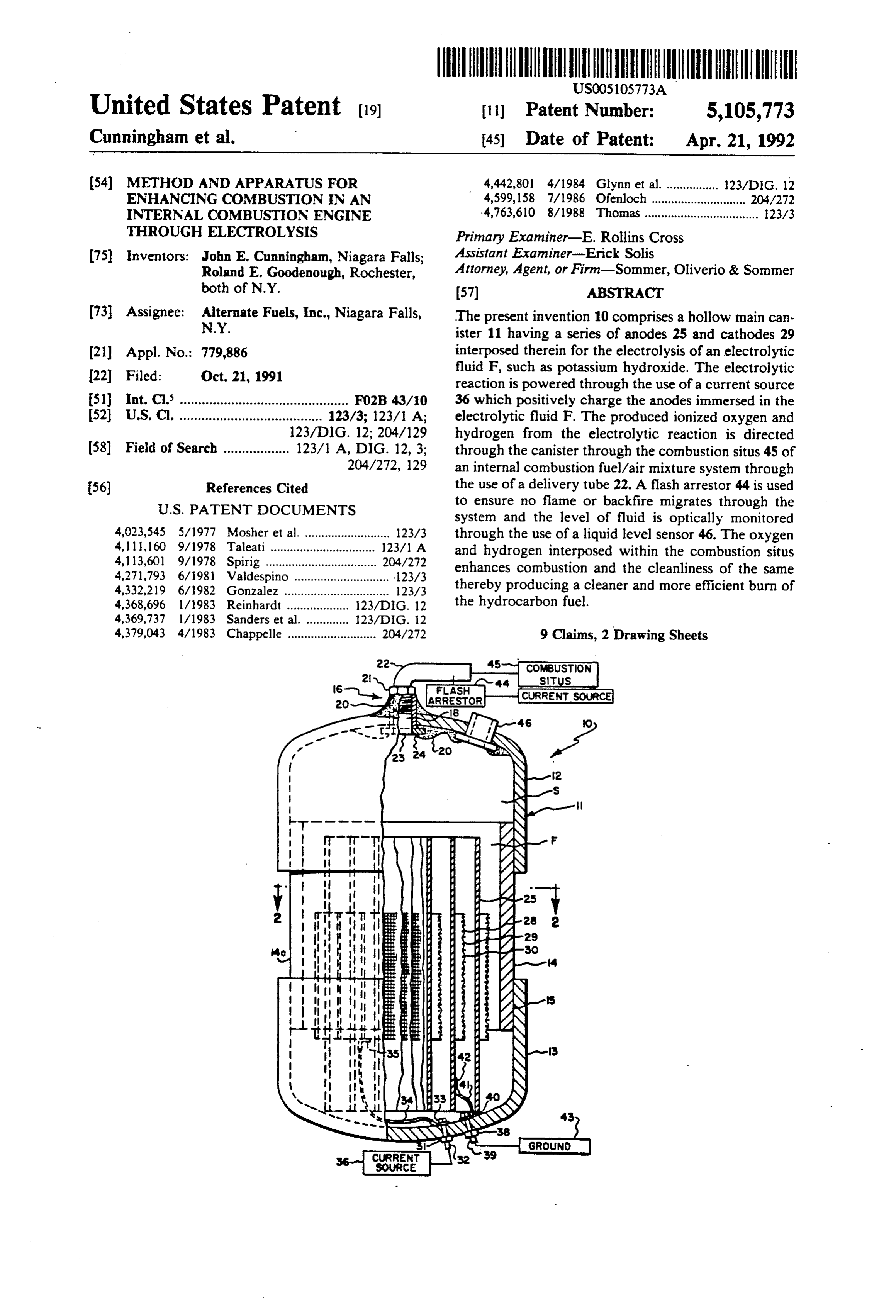
Cunningham et al. (45) Date of Patent: Apr. 21, 1992 (54) METHOD AND APPARATUS FOR 4,442,801 4/1984 Glynn et al... ... 123/DIG. 12 ENHANCNG COMBUSTION IN AN 4,599,158 7/1986 Ofenloch ............................. 204/272 INTERNAL COMBUSTON ENGINE 4,763,610 8/1988 Thomas ................................... 23/3 THROUGH ELECTROLYSIS Primary Examiner-E. Rollins Cross 75) Inventors: John E. Cunningham, Niagara Falls; Assistant Examiner-Erick Solis Roland E. Goodenough, Rochester, Attorney, Agent, or Firm-Sommer, Oliverio & Sommer both of N.Y. (57) ABSTRACT 73) Assignee: Alternate Fuels, Inc., Niagara Falls, The present invention 10 comprises a hollow main can N.Y. ister 11 having a series of anodes 25 and cathodes 29 (21) Appl. No.: 779,886 interposed therein for the electrolysis of an electrolytic
fluid F, such as potassium hydroxide. The electrolytic reaction is powered through the use of a current source 51) int.C. .............................................. FO2B 43/10 36 which positively charge the anodes immersed in the 52) U.S. C. ....................................... 123/3; 123/1 A; electrolytic fluid F. The produced ionized oxygen and 123/DIG. 12; 204/129 hydrogen from the electrolytic reaction is directed 58 Field of Search .................. 123/1 A, DIG. 12, 3; through the canister through the combustion situs 45 of 204/272, 129 an internal combustion fuel/air mixture system through 56) References Cited the use of a delivery tube 22. A flash arrestor 44 is used
system and the level of fluid is optically monitored 4,023,545 5/1977 Mosher et al. .......................... 123/3 through the use of a liquid level sensor 46. The oxygen 4, 11, 60 9/1978 Taleati.......... ... 123/1 A and hydrogen interposed within the combustion situs 4,113,60l 9/1978 Spirig ........... ... 204/272 enhances combustion and the cleanliness of the same 4,271,793 6/1981 Valdespino ...123/3 4,332,219 6/1982 Gonzalez .. ... 123/3 thereby producing a cleaner and more efficient burn of 4,368,696 l/1983 Reinhardt ..... ADG, 12 the hydrocarbon fuel.
4,379,043 4/1983 Chappelle ........................... 204/272 9 Claims, 2 Drawing Sheets
Page 2
Drawing sheet — no readable text.
Page 3
Drawing sheet — no readable text.
Page 4
ing of the same and by employing a unique mesh design
METHOD AND APPARATUS FOR ENHANCING for the anodes.
COMBUSTION IN AN INTERNAL COMBUSTION Accordingly, by carefully controlling the electrolytic ENGINE THROUGH ELECTROLYSS reaction, the proper amount of hydrogen and oxygen to enhance combustion (i.e., safe combustion) is produced
TECHNICAL FIELD and delivered to the combustion site (e.g., a carburetor) The present invention relates generally to internal without the need for storage tanks, pressure valves and combustion engines and the use of electrolytically gen the like. Nonetheless, the present invention includes a erated hydrogen and oxygen to enhance combustion flash arrestor which automatically prevents any flame, efficiency and cleanliness and more particularly, to an 10 backfire or other misfiring occurring in the carburetion electrolyser device designed for use in automobiles or or fuel injection area from migrating back through the other vehicles that produces the requisite amounts of system into the electrolyser and engine compartment hydrogen and oxygen through the variation of surface area thereby avoiding any potential explosive or other area and orientation of the electrolytic anodes and cath dangerous condition. Too, it is contemplated that in lieu odes. of a flash arrestor, the invention could include a pres
BACKGROUND OF THE INVENTION
sure detection device wherein pressures in excess of a set limit occurring in the delivery tube or fuel/air mix
A typical internal combustion engine such as that ture system would result in termination of the electroly generally used in automobiles, trucks and other similar 20 sis process.
vehicles uses hydrocarbon fuels for combustion. It is Thus, the present invention solves the problems of well known that the burning of such fuels is not one the prior art in a simple, straightforward and readily hundred percent efficient and further, produces large adaptable manner.
amounts of pollutants as a byproduct of the combustion DISCLOSURE OF THE INVENTION process. Accordingly, many attempts have been made 25 to enhance the completeness of combustion by the in The present invention (e.g. 10) provides a device to troduction of various catalysts and additives, including be interposed within an internal combustion fuel system gaseous hydrogen and oxygen into the burning process. for generating through electrolysis gaseous hydrogen Such attempts were made with the goal of improving and oxygen capable of delivery to the combustion site combustion efficiency and cleanliness, while ensuring 30 to increase the efficiency and cleanliness of combustion. the stability of the combustion process and viability of In particular, the preferred embodiment of the device engine components. includes a hollow canister (e.g. 11), having a top portion In particular, many attempts have been made in the (e.g. 12) and a bottom portion (e.g. 13); a series of three prior art to use a basic electrolysis reaction of various cylindrical cathodes (e.g. 25), preferably of nickel, each solutions (water or other chemical compositions con 35 having a variable diameter such that the cathodes may taining oxygen and hydrogen) to produce elemental be spaceably arranged one within the other; a series of oxygen and hydrogen in gaseous form. These gases, three stainless steel mesh anodes (e.g. 28) each of vari known to increase the efficiency of combustion within able diameter and adapted to fit one within the other said certain ranges, are then typically introduced either and further, within the spaces between the cathodes; a singly or together into the combustion situs in hopes of 40 nonconductive mesh (e.g. 30) encasing the stainless steel achieving the goal of improved combustion efficiency mesh (e.g. 29) of each of the anodes and adapted to and concomitant cleanliness. For example, U.S. Pat. insulate the anode from inadvertently touching the No. 4,111,160 (Talenti) provides a broad overview of cathodes; an epoxy coated anode connector post (e.g. the prior art attempts and the use of the basic electroly 31) interposed within the bottom portion of the main sis reaction to achieve enhanced combustion. 45 canister and adapted to be connected, at one end, to As can be seen from the prior art, controlling the each of the anodes and at the other end to a positive amount of hydrogen and oxygen produced during the current source (e.g. 36); an epoxy coated cathode con course of electrolysis is a key consideration. In particu nector post (e.g. 38) interposed through the bottom of lar, numerous efforts have been made to provide stor the main canister and adapted to be connected at one age tanks for excess elemental hydrogen and oxygen, to end to each of said cathodes and at the other end to a vent produced oxygen to the atmosphere while using ground point (e.g.43); a delivery fitting (e.g. 16) inter primarily hydrogen to enhance combustion, providing posed within the top portion of the main canister and pressure balancing systems (e.g., Talenti) to achieve a adapted to form a passageway connecting the hollow measured and verifiable electrolysis reaction, together inside of the main canister and the outside thereof; a with other safety means to avoid an uncontrolled com 55 delivery tube (e.g. 22) interposed at the outside end of bustion reaction or detrimental effects upon engine the delivery fitting and adapted to carry fluid there components. through; an electrolytic fluid (e.g. F), such as potassium The present invention solves these problems by em hydroxide, contained within the main canister and hav ploying a unique combination of anodes and cathodes in ing a sufficient volume to cover the surface area of the an easily adaptable environment within the fuel system; anodes and cathodes, while leaving a air space (e.g. 5) at i.e., the air-fuel mixture system, to produce an electroly the top of the main canister; a flash arrestor (e.g. 44) sis reaction and to enhance combustion without the interposed within the delivery tube for precluding mi need for storage tanks, pressure valves and the like in a gration of any flame or backfire occurring in the fuel-air safe and efficient manner. Accordingly, the present system area (at the carburetor or injection area) through invention contemplates controlling the underlying elec 65 to the electrolysis device; and liquid level sensor (e.g. trolytic reaction by carefully varying the surface areas 46) interposed through the top surface of the main can of the anodes and cathodes powering the reaction ister for optically determining the level of the electro through the use of variable horizontal and vertical spac lytic fluid within the canister.
Page 5
In operation, the device produces gaseous hydrogen the terms "horizontal", "vertical", "left", "right", "up" and oxygen through an electrolytic reaction. In particu and "down', as well as adjectival and adverbial deriva lar, the positive current positively charges the anodes tives thereof (e.g., "horizontally", "rightwardly", "up causing the typical electrolysis reaction of the potas wardly', etc.), simply refer to the orientation of the sium hydroxide or other electrolyte thereby freeing 5 illustrated structure as the particular drawing figure gaseous oxygen and hydrogen which, in turn, surfaces faces the reader. Similarly, the terms "inwardly' and at the top portion of the main canister. The hydrogen "outwardly' generally refer to the orientation of a sur and oxygen mixture is then delivered through the deliv face relative to its axis of elongation, or axis of rotation, ery fitting through the delivery tube to the combustion as appropriate.
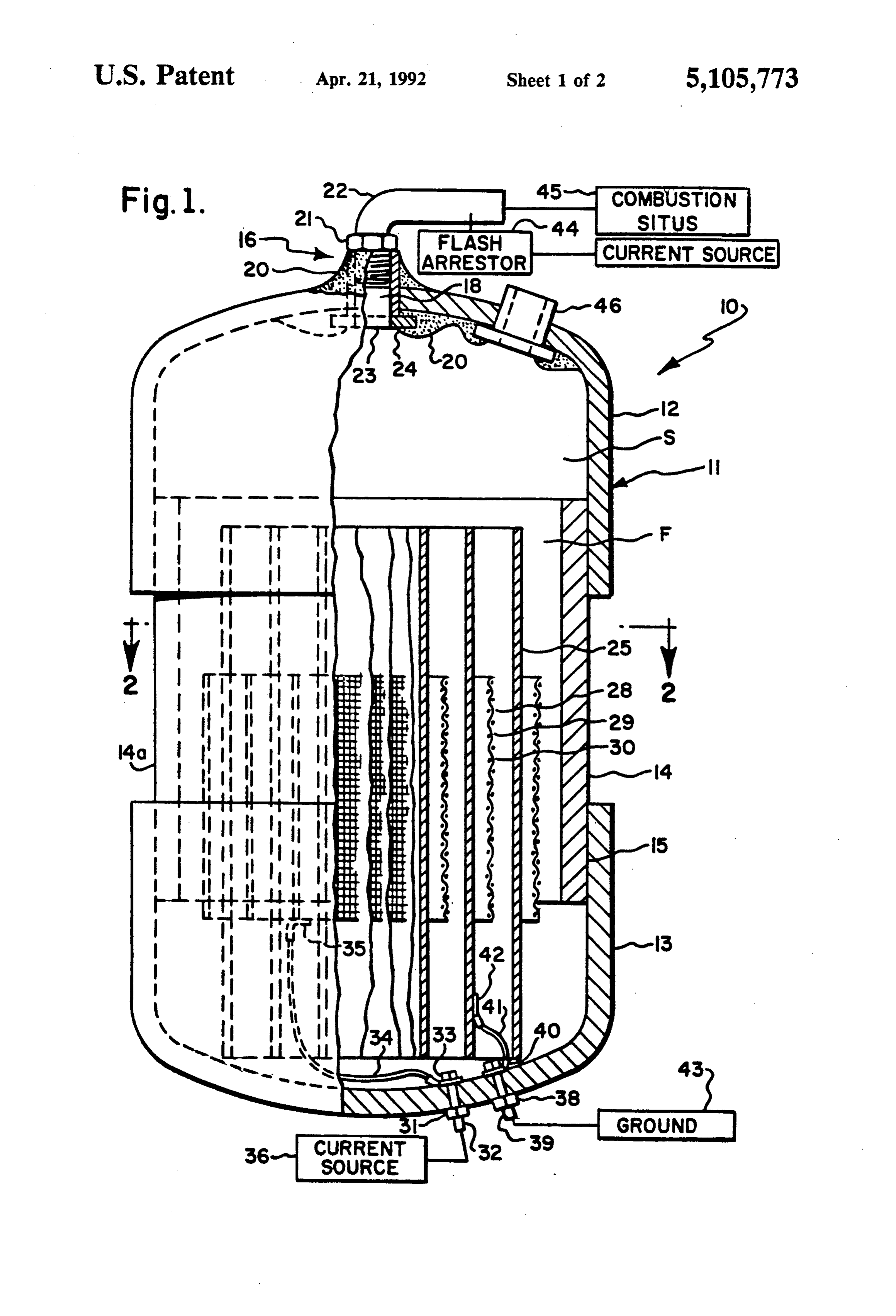
site of the fuel/air system and is ignited in the ordinary 10 Adverting first to FIG. 1, the device 10 is shown to manner, e.g., by a spark plug, as the internal combustion generally comprise a hollow main canister 11 generally engine functions to burn its normal hydrocarbon fuel. comprised of a hollow inverted cup-shaped top portion The amount of hydrogen and oxygen produced, critical 12, and cup-shaped bottom portion 13 joined on their to the efficiency and safety of the reaction, is controlled inside portions by parallel vertical side members 14 and through a careful positioning of the anodes and cath- 15 14A. The main canister is normally fabricated from odes; i.e., by varying the lateral spacing and relative lightweight PVC material or a similar material to mini vertical orientation of the anodes and cathodes as well mize weight while maintaining durability and sealing as the surface area of the anodes through the use of capability. In particular, the top and bottom portions mesh rather than a solid anode material. Accordingly, are joined to the side portions of the main canister by the amount of hydrogen and oxygen produced through 20 overlapping the facing planar surfaces at, for example, the normal electrolysis reaction may be accurately de 15. This further ensures the structural stability and seal termined by virtue of the orientation of the anodes and ing capability of the canister during operation of the cathodes and thus, the amount of hydrogen and oxygen device.
produced by the reaction may be controlled. Thus, Continuing to advert to FIG. 1, a substantially cylin there is no need for storage tanks, pressure control 25 drical delivery fitting 16 is interposed through the wall valves or other devices to monitor the reaction aside of the top portion 12 at a point directly at the top from the flash arrestor device or other control device thereof to form a circular passageway 18 therethrough. used as a safety feature to override any electrolytic Passageway 18 is generally threaded on its inside por reaction that may, for whatever reason, be outside the tion to accept in sealing engagement a hollow screw bounds of normal operation of the engine at hand. 30 plug 19 therein. Screw plug 19 ensures solid engage Thus, the primary object of the invention is to pro ment and sealing of the passageway while permitting vide a controlled device for producing hydrogen and the flexible connection of delivery tube 22 at the outside oxygen through electrolysis and delivering the same to end thereof. Connection of delivery tube 22 and screw the combustion site of an internal combustion engine. plug 19 is facilitated through the use of a complemen Still another object of the invention is to produce 35 tary top cap 21 adapted to engage the top of the hollow hydrogen and oxygen through electrolysis that may be screw plug and form a joining connector between the delivered to an internal combustion engine combustion top of the screw plug and the delivery tube 22. Addi site without the need for storage tanks, valves or the tional sealing material 20, such as PVC cement or glue like. impervious to gas, heat or water is interposed around Still another object of the invention is to provide 40 the screw cap to further ensure sealing engagement and controlled amounts of hydrogen and oxygen to the the integrity of the delivery fitting and passageway. combustion site without the need for constant monitor Continuing to advert to FIG. 1, that portion of the ing and through the use of a particularized structure of delivery fitting extending into the hollow portion of the the electrolysis device. main canister terminates by engaging a connector and These and other objects of the invention will become 45 seal assembly 24 adapted to be affixed to the end of the apparant from the foregoing and ongoing written speci delivery fitting and passageway to seal the inside por fication, the drawing figures and claims that follow. tion thereof and further ending in an opening 23. PVC
BRIEF DESCRIPTION OF THE DRAWINGS
cement or glue is also interposed on the inside of top portion 12 to seal the delivery fitting and passageway
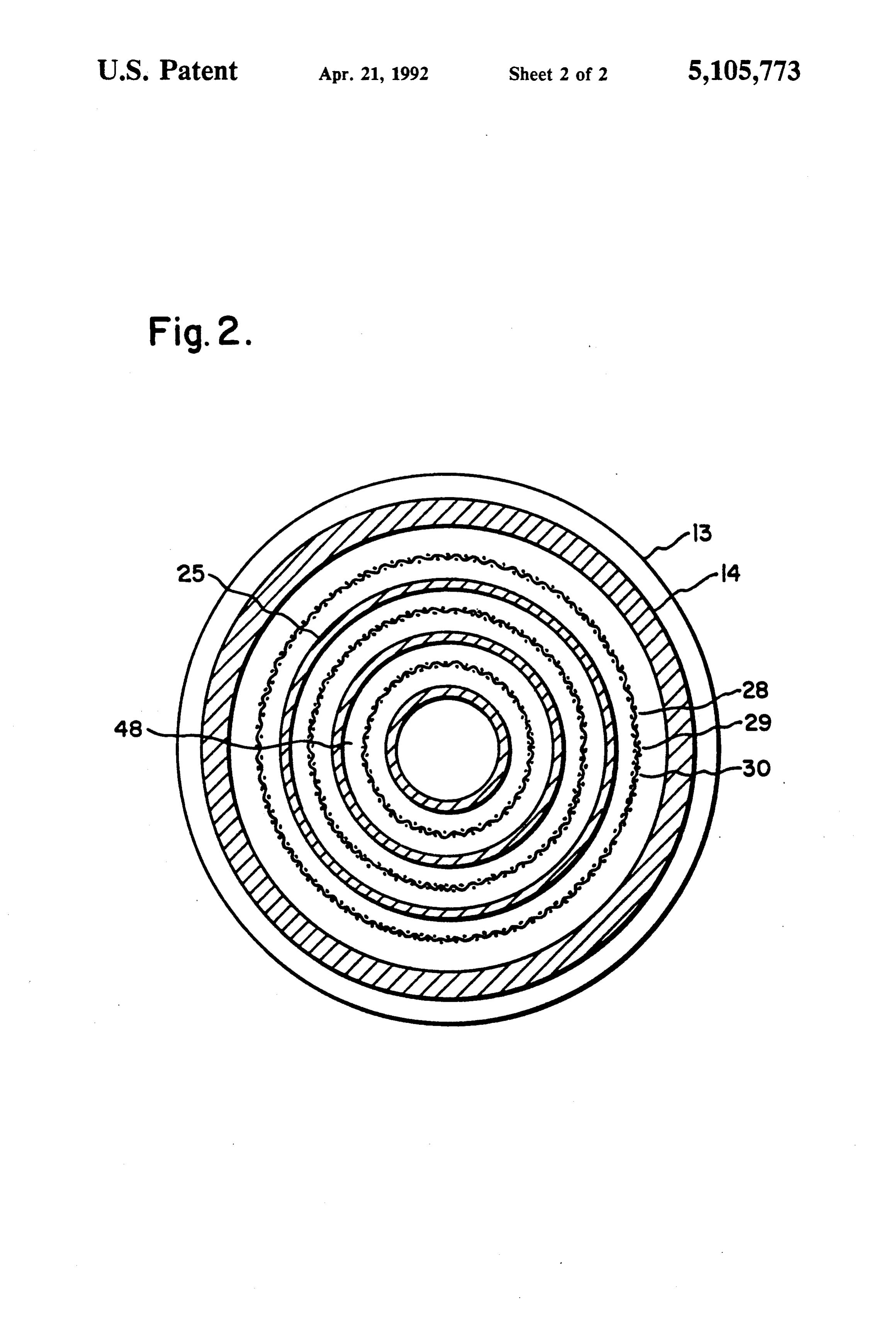
FIG. 1 is a fragmentary longitudinal sectional view of 50 within the main canister hollow. the preferred embodiment of the device showing the Delivery tube 22 extends to the combustion situs 45 spacing and interposition of the anodes and cathodes. of the internal combustion engine and fuel/air mixture FIG. 2 is a horizontal sectional view of the device system into which the device is incorporated. For ex along 2-2 of FIG. 1. ample, the combustion situs 45 may be, in a normal 55 internal combustion engine, the air cleaner and carbure
MODE(S) OF CARRYING OUT THE INVENTION tor assembly on the top of the engine or similarly, in a At the outset, it should be clearly understood that like fuel injection system, in the air induction or air cleaner reference numerals are intended to identify the same C3.
structural elements, portions or surfaces consistently Adverting to FIGS. 1 and 2, the anode and cathode throughout the several drawings figures, as such ele- 60 structure of the device is shown. In particular, the de ments, portions or surfaces may be further described or vice includes a series of three cylindrical, thin-walled explained by the entire written specification, of which cathodes 25 usually comprised of nickel and having this detailed description is an integral part. Unless oth varying diameters such that each of the three cathode erwise indicated, the drawings are intended to be read cylinders may be placed one within the other. The cath (e.g., cross-hatching, arrangement of parts, proportion, 65 odes are arranged and dimensioned in such a manner degree, etc.) together with the specification, and are to that a space, e.g., 48, is formed therebetween when the be considered a portion of the entire written description cathodes are arranged one within another. This space of this invention. As used in the following description, 48, of course, can be varied by varying the diameter of
Page 6
each of the cathodes as desired. Continuing to advert to tion, cathode electrical connector 39 is connected to a FIG. 1 and 2, the cathodes are shown to be arranged at ground point, 43, somewhere in the automobile. the identical vertical height; however, in practice, the Accordingly, when fully interposed within the fuel height of the cathodes may be varied with respect to system, each of the anodes is capable of being supplied one another by an appropriate mounting means or sus with a positive current source 36 through use of the pension in the main canister hollow. epoxy coated anode connector post and internal wiring Continuing to advert to FIGS. 1 and 2, the device is such that each of the anodes may be positively charged shown to further include a series of three anodes, 28, of during the course of operation. Similarly, each of the cylindrical shape. Anodes 28 are comprised of two cathodes is externally grounded through the use of an portions, namely, a stainless steel mesh at preselected O identical wiring arrangement terminating in a ground hole dimension formed into a cylinder of a preselected point outside the device somewhere on the automobile vertical height. The stainless steel mesh cylinder is fur or vehicle incorporating the device in the internal com ther encased by a non-conductive (e.g., plastic or PVC) bustion and fuel system.
mesh acting as a barrier or insulator for the underlying S lowAnofelectrolytic the main fluid F is interposed within the hol canister in a sufficient volume to cover stainless steel mesh of the anode. The diameter dimen all or the majority of the anode and cathode surfaces.
sion of the anode is selected such that each may be Typically, arranged one within another and within the spaces 48 or a similarthe electrolytic fluid is potassium hydroxide compound able to generate free oxygen and between the cathodes. Accordingly, as shown in FIG. hydrogen ions as a result of an electrolytic reaction. 2, the inner portion of the device comprises a series of six cylinders one within another alternating between O The volume of fluid F will generally not entirely fill the cathodes and anodes and having preselected spaces hollow the top canister and a space S, will typically be left at portion thereof.
therebetween without touching or contact. Too, the Completing the components of the device is the inter anodes may be positioned vertically at various points position of a flash arrestor 44 within the delivery tube with respect to one another and with respect to the 25 22. The flash arrestor is adapted to detect any flame, cathode, as desired in the context of the electrolysis backfire or other misfiring disturbance occurring at the reaction discussed below. Similarly, the spacing be fuel/air mixture point and prevents the migration of any tween the anodes and cathodes may also be varied by varying the diameters of both the anodes and cathodes flame or other potentially hazardous liquid or gas through the system into the electrolysis reaction area.
in the desired fashion. 30 Although a flash arrestor is shown in the preferred Although the anodes and cathodes are described to embodiment, a pressure detection device may also be be nickel in the preferred embodiment, other materials employed which detects increases in pressures beyond a such as platinum coated nickel may be employed pro pre-set limit in the delivery system. If this condition is vided the reaction may be controlled in the manner sensed, the pressure sensor may be operatively con described. The materials comprising the anodes and 35 nected to the electrolysis canister or current source to cathodes are chosen not only for the reactive proper effect immediately termination. The preferred embodi ties, but also with respect to their longevity, deteriora ment operates at a maximum pressure of approximately tion and overall electrolysis activity. These factors need one-half PSI and further, comprises an "open-ended to be balanced to achieve a desirable material combina discharge' system thereby reducing volatility. Accord tion which, as in the preferred embodiment, has a useful ingly, pressures in excess of the one-half PSI or any life of three years or more in the presence of potassium other suitable range could be easily detected by a simple hydroxide or other similar electrolytes. pressure detection device.
Adverting to FIG. 1, epoxy coated anode connector The device further includes a fluid level sensor 46 post 31 is interposed through the wall of bottom portion such as an optical liquid level sensor or other type de 13. Epoxy coated anode connector 31 terminates at 45 vice by which the level of fluid F within the canister either end with a connecting point and screw 32 and 33 hollow may be detected optically by looking through adapted to receive a connecting wire 34. Epoxy coated the sensor. These types of sensors are typically seen in anode connector post 31, at its outside portion is con maintenance-free auto batteries wherein it is not neces nected to current source 36 which may be, in the case of sary to uncap the battery to determine the level of liquid an automobile, the automobile battery or an appropriate SO or fluid therein. Fluid level sensor 46 is sealingly inter point in the fuse box of the vehicle. The current source posed through the wall of top portion 12 by either is able to travel through the epoxy coated anode con threading or the use of an appropriate sealing media nector post 31 and appended connector 33 through such as PVC cement, glue or the like.
anode wire 34 which is connected at its other end to In operation, the device is interposed within the en each of the anodes at a point, e.g., 35. Although not 55 gine compartment of an internal combustion engine and specifically shown in FIG. 1, each of the anodes is con is arranged to communicate with the combustion situs nected to the epoxy coated anode connector post and 45 such as the carburetor and air cleaner components or ultimately the current source in an identical manner. fuel injection area. The device is also connected to a Still considering FIG. 1, epoxy coated cathode con power source, e.g., the battery or fuse box, in order that nector post 38 is similarly interposed through the wall a small amount of positive current may be provided of bottom portion 13 and terminates at either of its ends through the device. The device is also typically with wire connectors 38 and 40. In particular, connec grounded at a ground point 43 on the automobile frame tor 40, on the inside portion of the epoxy coated cath or engine compartment.
ode connector post is adapted to engage cathode wire In a normal electrolysis reaction, a current is supplied 41 which, in turn, engages each of the cathodes at a 65 to the anodes which, in consort with the cathodes and point 42, as shown in FIG. 1. Each of the cathodes is electrolytic fluid F (potassium hydroxide in the pre connected to the cathode post through a similar wire ferred embodiment) produces a chemical reaction re arrangement as is shown in FIG. 1. At its outside por sulting in the production of free oxygen and hydrogen
Page 7
ions which migrate to the top portion of the hollow cathodes may be readily varied to produce an appropri main canister. The gaseous hydrogen and oxygen is ate reaction for the vehicle at hand. directed through the opening tube 23 and delivery fit Too, mesh screens of variable dimension and orienta ting 16 through delivery tube 22 to the combustion situs tion, together with appropriate cathode cylinders of 45. Flash arrestor 44 ensures that the reaction has not various materials may be employed depending upon the produced a flame or backfire and is well within safe reaction required.
limits. The hydrogen and oxygen is merged in the usual These and other modifications and changes to the combustion situs of the engine and serves to enhance invention would be readily apparent to one of skill in burning of the typical hydrocarbon fuels thereby im the art and anticipated by the specification and descrip proving the efficiency of the burn and the cleanliness of O tionWeofcairn:
the invention, as well as the following claims.
the same.
The normal electrolysis reaction will produce ap 1. An electrolyser device for use in an internal con proximately 66 percent hydrogen and 33 percent oxy bustion engine fuel/air mixture system for enhancing gen. The percent of hydrogen and oxygen, however, combustion, comprising:
can be varied by varying the surface area and spacing 15 a main canister, interposed within said internal con bustion fuel/air mixture system, said canister hav (vertically and laterally) of the cathodes and anodes. In ing a top portion and a bottom portion and side particular, more hydrogen can be produced by decreas portions forming a hollow cavity and adapted to ing the surface area of the anodes. This is accomplished sealably contain a fluid therein; in the present invention through the use of stainless steel 20 a delivery fitting interposed on the top surface of said mesh, as opposed to a solid surface and by selectively main canister and forming a communicating pas spacing the distance between the anodes and cathodes sageway between said inside hollow of said canis according to the desired reaction required. Accord ter and the outside of said canister; ingly, once the proper dimensions are configured for a delivery tube flexibly attached to said outside por the device, the requisite amount of hydrogen and oxy tion of said delivery fitting and adapted to carry gen can be accurately predicted within safe limits. The fluids therethrough;
present invention produces approximately 85 percent a plurality of cathodes interposed within said inside of hydrogen and 15 percent oxygen at a constant level of said main canister and fixably supported thereby, approximately 2-4 amps. Accordingly, it is not required said cathodes each further comprising a hollow to have storage tanks, pressure valves or monitoring 30 cylinder each of preselected different diameter devices, aside from the general safety flash arrestor or such that each of said cathode cylinders is adapted sensor, to operate the device. Too, the open ended to be spaceably arranged one within the other; discharge characteristics of the system reduce a plurality of anodes interposed within said hollow volativity substantially. The measurements, of course, inside of said main canister and fixably supported will depend upon engine size and requirements and can 35 thereby, each of said anodes further comprising a be easily calculated and determined through experimen hollow stainless steel mesh cylinder each of prese tation. Thus, by merely varying the space and vertical lected different diameters such that each of said orientation of the anodes and cathodes and the surface anodes is adapted to be arranged one within the area thereof, it is possible to produce the desired amount other and within said spaces between said cath of hydrogen and oxygen through simple electrolysis of 40 odes, said anodes further comprising a covering potassium hydroxide and deliver the same to the com non-conductive mesh encasing said stainless steel bustion situs of the internal combustion engine. For mesh;
example, in the preferred embodiment of the invention, a cathode electrical connector post interposed the stainless steel mesh has a screen size of ' and the through said bottom of said main canister and anodes and cathodes are positioned' apart. 45 adapted at either end to be engaged by an electrical Further, the invention will operate with the small connector means, said cathode electrical connector amount of current (e.g. 2-4 amps) produced through the arranged at one end to be connected to each of said auto battery or fuse box and does not require a second cathodes and at the other end thereof to a ground ary power source. This, too, enables the device to be as point;
unobtrusive as possible in the engine compartment and SO an anode electrical connector post interposed does not require the addition of weight or bulk to the through said bottom of said main canister and automobile or vehicle at hand. Moreover, the device is adapted at either end to be engaged by an electrical readily adaptable for use with carbureted engines or connector means, said anode connector engaged at fuel injection devices and also, with diesel engines. one end to each of said anodes and at the other end Finally, the use of the optical liquid level sensor per 55 to a source of positive electrical current such that mits easy maintenance of the device and allows the upon application of said current, said anode be electrolytic fluid F, to be refilled at appropriate inter comes positively charged; vals to maintain the reaction desired. an electrolytic fluid, containing hydrogen and oxy MODIFICATIONS TO THE INVENTION gen, interposed within said main canister such that the surface area of said anodes and said cathodes
Although a single embodiment of the invention is are covered thereby;
disclosed, it is clear from the specification, drawings whereby upon application of the positive electric and description of the invention that many modifica current to the anodes, electrolysis reaction occurs tions and changes may be made without departing from freeing gaseous oxygen and hydrogen through said the invention. 65 delivery valve and delivery tube dependent upon For instance, although potassium hydroxide is used as said orientation of said anodes and cathodes. the electrolytic fluid, other fluids of similar characteris 2. The device according to claim 1 wherein said elec tics could be used. Moreover, the number of anodes and trolytic fluid is potassium hydroxide.
Page 8
3. The device according to claim 1 further compris to cover the surface areas of each of said anodes ing a liquid level sensor interposed through the top of and cathodes;
said main canister for optically determining the level of providing a delivery fitting at the top of said main said electrolytic fluid in said canister hollow inside canister such that there is a communicating pas portion. 5 sageway between said canister hollow inside and 4. The device according to claim 1 and further com outside;
prising a flash arrestor interposed within said delivery providing a delivery tube flexibly attached to said tube, and adapted to automatically preclude migration delivery valve and adapted to carry a fluid there of any flame or backfire from said fuel-air mixture sys through;
ten to said main canister. O varying said spaces between said anodes and cath 5. The device according to claim 1 wherein said an odes, said surface areas of said anodes and cathodes odes are stainless steel and said cathodes are nickel. and said vertical orientation of said anodes and 6. In an internal combustion engine fuel system hav cathodes such that upon application of said positive ing a combustion site, such as a carburetor, the method current, electrolysis of said electrolytic fluid oc of providing gaseous oxygen and hydrogen through 5 curs such that a desired amount of oxygen and electrolysis to enhance combustion, comprising the hydrogen are produced;
steps of: venting said produced oxygen and hydrogen gas providing a hollow main canister within said fuel through said delivery fitting and delivery tube to system adapted to sealably contain a fluid; said combustion site of said internal combustion providing a plurality of cylindrical cathodes of vary- 20 engine and fuel/air mixture system; ing diameter such that each of said cathodes may whereby the introduction of gaseous hydrogen and be arranged one within the other and such that oxygen into the combustion process enhances the there is a space therebetween; completeness and cleanliness of the same. providing a plurality of conductive mesh cylindrical 7. The method according to claim 6 wherein said anodes of varying diameter such that each of said 25 anodes may be arranged within the other and electrolytic fluid is potassium hydroxide.
within said spaces between said cathodes; 8. The method according to claim 6 further compris providing a non-conductive mesh encasing said an ing the step of providing a liquid level sensor interposed odes; on the top of said main canister such that said volume of providing a positive current to each of said anodes 30 said electrolytic fluid may be optically determined. whereby said anodes may be selectively electri 9. The method according to claim 6 further compris cally positively charged; ing the step of providing a flash arrestor within said providing a ground to each of said cathodes; delivery tube such that upon detection of a flame or providing a volume of electrolytic fluid within said backfire, migration to said hollowk k canister
is precluded.
main canister, said provided fluid volume sufficient 35
Provenance
- Collection
- Cited prior art
- Original PDF
- patentimages.storage.googleapis.com →
- Filed
- 1991-10-21
- Pages
- 8
- Method
- pdftotext (the PDF's own text layer) + pdftoppm 300dpi page scans
- Source
- Google Patents bibliographic record
- Granted
- 1992-04-21
- Inventors
- John E. Cunningham; Roland E. Goodenough; Alternate Fuels Inc
- Transcribed from
- patentimages.storage.googleapis.com →