patent · US3311097
Hydrogen-oxygen device in combustion engines
28 March 1967
Page 1
Drawing sheet — no readable text.
Page 2
Drawing sheet — no readable text.
Page 3
Drawing sheet — no readable text.
Page 4
Drawing sheet — no readable text.
Page 5
United States Patent Office 3,311,097 Patented Mar. 28, 1967
that 96,500 amp.-sec. of current produce 11,200 cc. of 3,311,097 hydrogen and 5,600 cc. of oxygen per cell. The gases
HYDROGEN-OXYGEN DEVICE IN being evolved are explosive, and it is well known that COMBUSTION ENGINES mixtures of hydrogen and oxygen explode violently if Georg S. Mittelstaedt, 274 73rd St., they are ignited by a spark. The automobile-battery gases Brooklyn, N.Y. 11209
Filed Nov. 24, 1964, Ser. No. 413,505 also frequently contain traces of antimony compound, 4 Claims. (C. 123-119) Stibine, which burns with a bluish-green flame. In this invention, the liberated hydrogen and oxygen
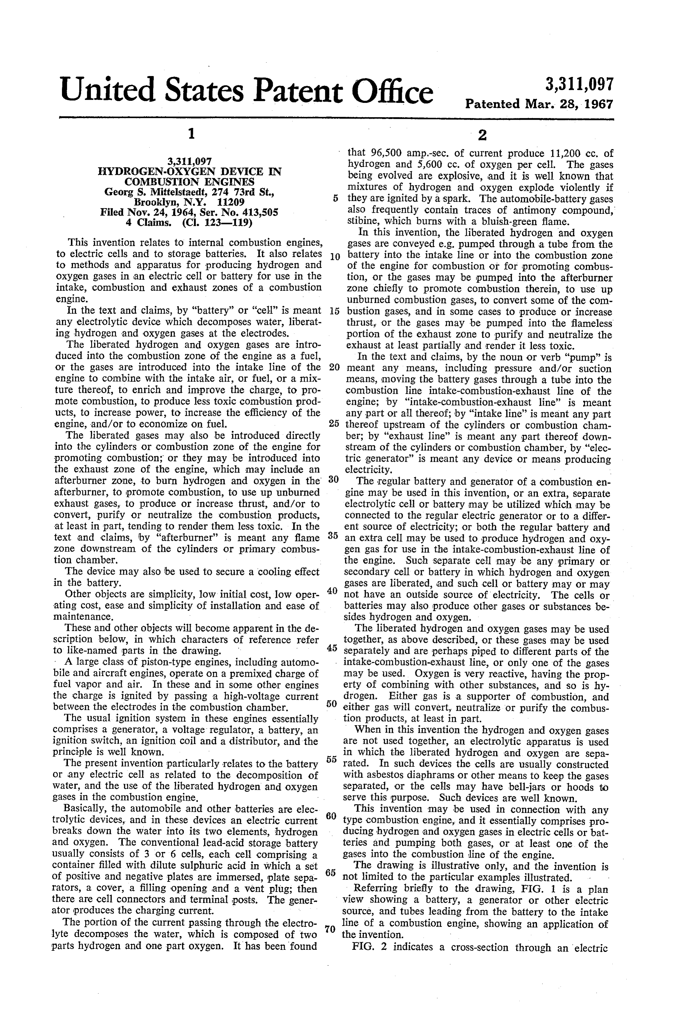
This invention relates to internal combustion engines, gases are conveyed e.g. pumped through a tube from the to electric cells and to storage batteries. It also relates 0. battery into the intake line or into the combustion zone to methods and apparatus for producing hydrogen and of the engine for combustion or for promoting combus oxygen gases in an electric cell or battery for use in the tion, or the gases may be pumped into the afterburner intake, combustion and exhaust zones of a combustion Zone chiefly to promote combustion therein, to use up engine. unburned combustion gases, to convert some of the com In the text and claims, by “battery” or “cell' is meant bustion gases, and in some cases to produce or increase any electrolytic device which decomposes water, liberat thrust, or the gases may be pumped into the flameless ing hydrogen and oxygen gases at the electrodes. portion of the exhaust zone to purify and neutralize the The liberated hydrogen and oxygen gases are intro exhaust at least partially and render it less toxic. duced into the combustion zone of the engine as a fuel, In the text and claims, by the noun or verb "pump' is or the gases are introduced into the intake line of the 20 meant any means, including pressure and/or suction engine to combine with the intake air, or fuel, or a mix means, moving the battery gases through a tube into the ture thereof, to enrich and improve the charge, to pro combustion line intake-combustion-exhaust line of the mote combustion, to produce less toxic combustion prod engine; by "intake-combustion-exhaust line' is meant ucts, to increase power, to increase the efficiency of the any part or all thereof; by "intake line' is meant any part engine, and/or to economize on fuel. 25 thereof upstream of the cylinders or combustion cham The liberated gases may also be introduced directly ber; by "exhaust line' is meant any part thereof down into the cylinders or combustion zone of the engine for stream of the cylinders or combustion chamber, by “elec promoting combustion; or they may be introduced into tric generator' is meant any device or means producing the exhaust zone of the engine, which may include an electricity. - afterburner zone, to burn hydrogen and oxygen in the 30 The regular battery and generator of a combustion en afterburner, to promote combustion, to use up unburned gine may be used in this invention, or an extra, separate exhaust gases, to produce or increase thrust, and/or to electrolytic cell or battery may be utilized which may be convert, purify or neutralize the combustion products, connected to the regular electric generator or to a differ at least in part, tending to render them less toxic. In the 35 ent source of electricity; or both the regular battery and text and claims, by “afterburner' is meant any flame an extra cell may be used to produce hydrogen and oxy zone downstream of the cylinders or primary combus gen gas for use in the intake-combustion-exhaust line of tion chamber. the engine. Such separate cell may be any primary or The device may also be used to secure a cooling effect Secondary cell or battery in which hydrogen and oxygen in the battery. gases are liberated, and such cell or battery may or may Other objects are simplicity, low initial cost, low oper 40 not have an outside source of electricity. The cells or ating cost, ease and simplicity of installation and ease of batteries may also produce other gases or substances be maintenance. sides hydrogen and oxygen.
These and other objects will become apparent in the de The liberated hydrogen and oxygen gases may be used scription below, in which characters of reference refer 45 together, as above described, or these gases may be used to like-named parts in the drawing. separately and are perhaps piped to different parts of the - A large class of piston-type engines, including automo intake-combustion-exhaust line, or only one of the gases bile and aircraft engines, operate on a premixed charge of may be used. Oxygen is very reactive, having the prop fuel vapor and air. In these and in some other engines erty of combining with other substances, and so is hy the charge is ignited by passing a high-voltage current 50 drogen. Either gas is a supporter of combustion, and between the electrodes in the combustion chamber. either gas will convert, neutralize or purify the combus The usual ignition system in these engines essentially tion products, at least in part.
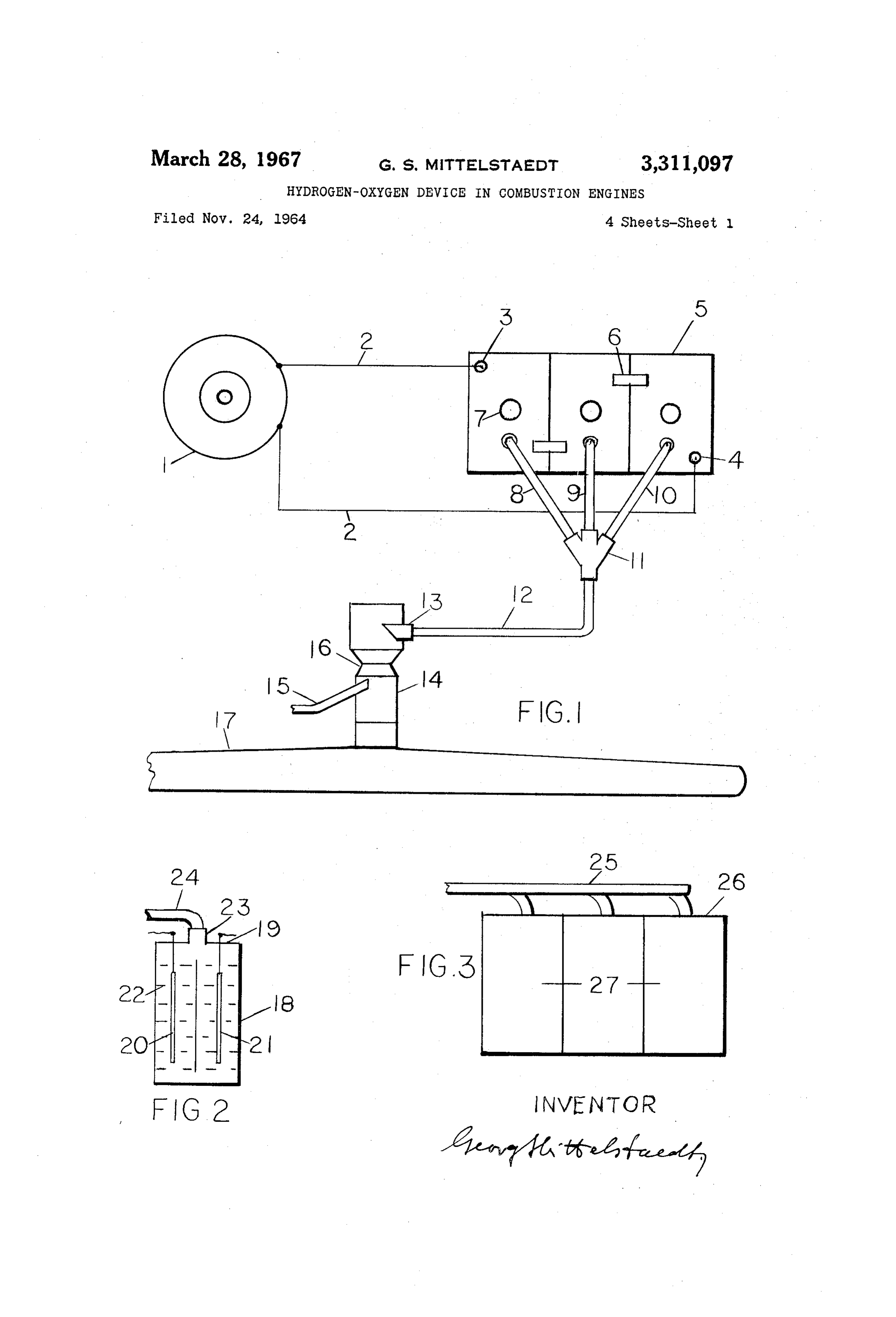
comprises a generator, a voltage regulator, a battery, an When in this invention the hydrogen and oxygen gases ignition switch, an ignition coil and a distributor, and the are not used together, an electrolytic apparatus is used principle is well known. in which the liberated hydrogen and oxygen are sepa The present invention particularly relates to the battery 55 rated. In such devices the cells are usually constructed or any electric cell as related to the decomposition of with asbestos diaphrams or other means to keep the gases water, and the use of the liberated hydrogen and oxygen separated, or the cells may have bell-jars or hoods to gases in the combustion engine. serve this purpose. Such devices are well known. Basically, the automobile and other batteries are elec 60 This invention may be used in connection with any trolytic devices, and in these devices an electric current type combustion engine, and it essentially comprises pro breaks down the water into its two elements, hydrogen ducing hydrogen and oxygen gases in electric cells or bat and oxygen. The conventional lead-acid storage battery teries and pumping both gases, or at least one of the usually consists of 3 or 6 cells, each cell comprising a gases into the combustion line of the engine. container filled with dilute sulphuric acid in which a set 65 The drawing is illustrative only, and the invention is of positive and negative plates are immersed, plate sepa not limited to the particular examples illustrated. rators, a cover, a filling opening and a vent plug; then Referring briefly to the drawing, FIG. 1 is a plan there are cell connectors and terminal posts. The gener view showing a battery, a generator or other electric ator produces the charging current. . source, and tubes leading from the battery to the intake The portion of the current passing through the electro 70 line of a combustion engine, showing an application of lyte decomposes the water, which is composed of two the invention.
parts hydrogen and one part oxygen. It has been found FIG. 2 indicates a cross-section through an electric
Page 6
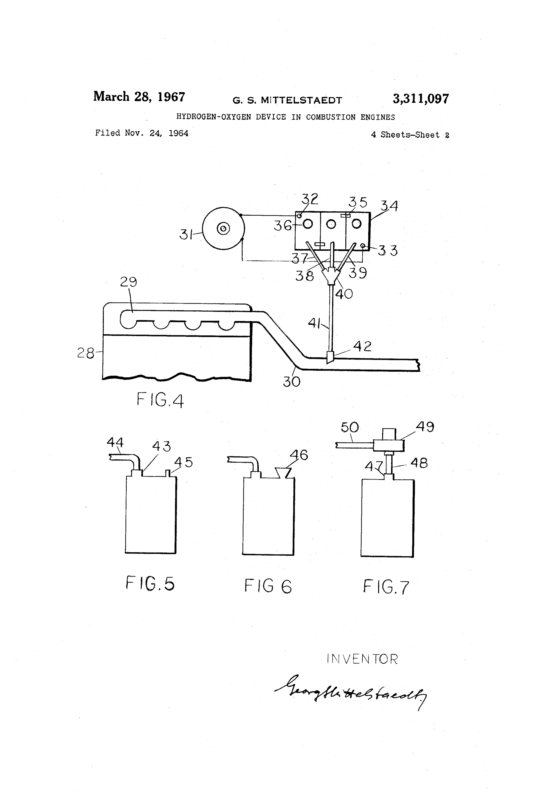
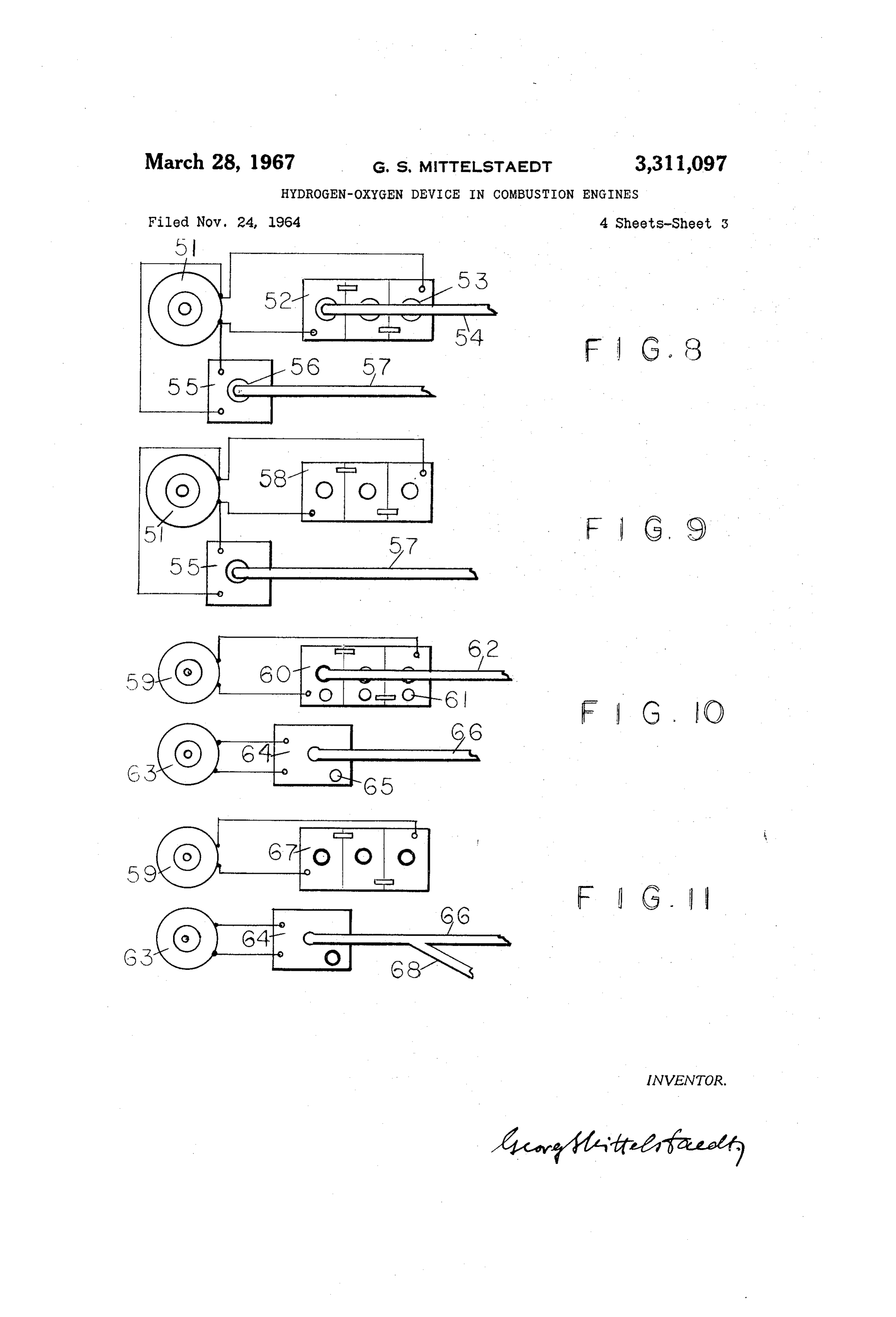
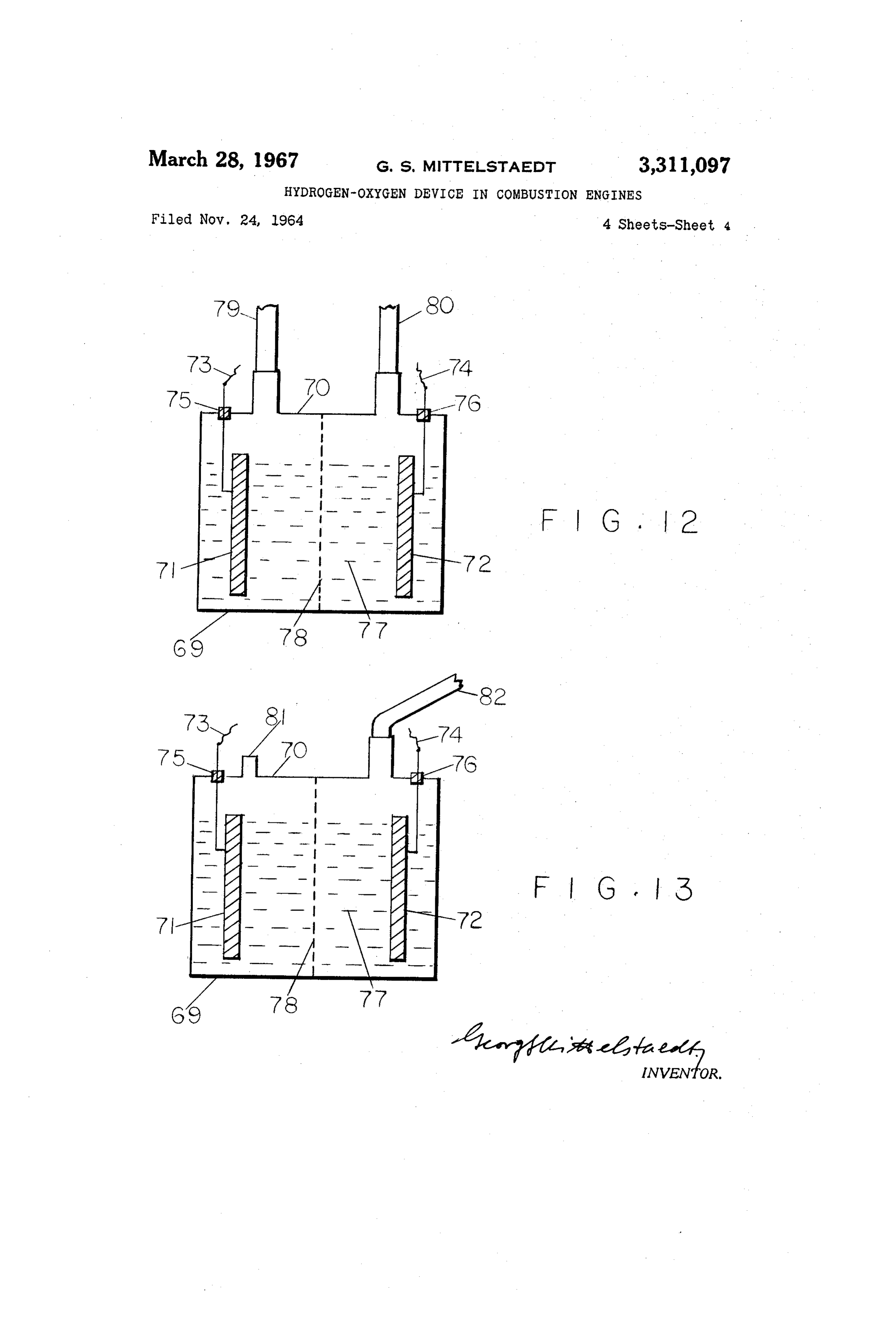
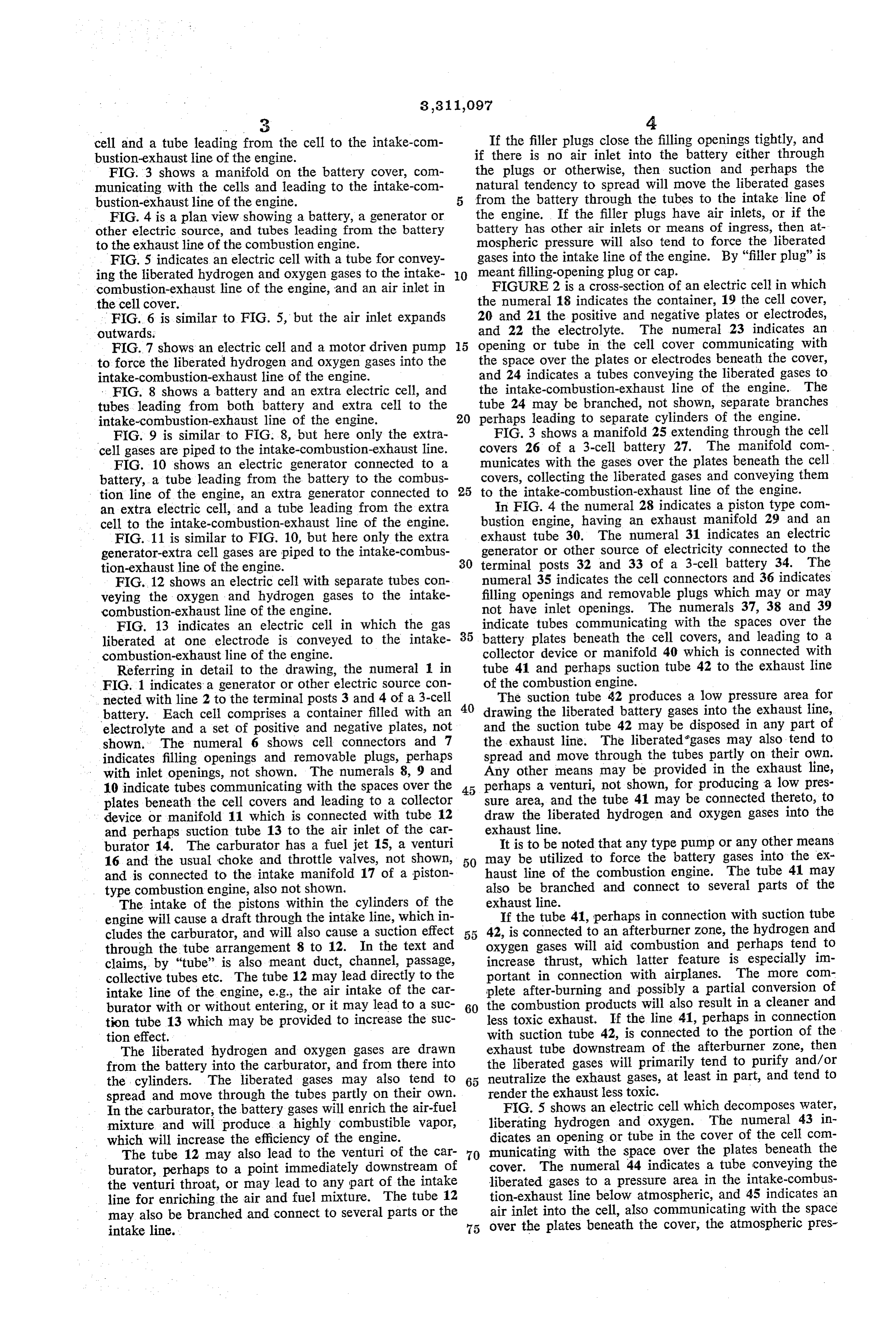
cell and a tube leading from the cell to the intake-com If the filler plugs close the filling openings tightly, and bustion-exhaust line of the engine. if there is no air inlet into the battery either through FIG. 3 shows a manifold on the battery cover, com the plugs or otherwise, then suction and perhaps the municating with the cells and leading to the intake-com natural tendency to spread will move the liberated gases bustion-exhaust line of the engine. from the battery through the tubes to the intake line of FIG. 4 is a plan view showing a battery, a generator or the engine. If the filler plugs have air inlets, or if the other electric source, and tubes leading from the battery battery has other air inlets or means of ingress, then at to the exhaust line of the combustion engine. mospheric pressure will also tend to force the liberated FIG. 5 indicates an electric cell with a tube for convey gases into the intake line of the engine. By "filler plug" is ing the liberated hydrogen and oxygen gases to the intake O meant filling-opening plug or cap.
combustion-exhaust line of the engine, and an air inlet in FIGURE 2 is a cross-section of an electric cell in which the cell cover. the numeral 18 indicates the container, 19 the cell cover, FIG. 6 is similar to FIG. 5, but the air inlet expands 20 and 21 the positive and negative plates or electrodes, outwards. and 22 the electrolyte. The numeral 23 indicates an FIG.7 shows an electric cell and a motor driven pump 5 opening or tube in the cell cover communicating with to force the liberated hydrogen and oxygen gases into the the space over the plates or electrodes beneath the cover, intake-combustion-exhaust line of the engine. and 24 indicates a tubes conveying the liberated gases to FIG. 8 shows a battery and an extra electric cell, and the intake-combustion-exhaust line of the engine. The tubes leading from both battery and extra cell to the tube 24 may be branched, not shown, separate branches intake-combustion-exhaust line of the engine. 20 perhaps leading to separate cylinders of the engine. FIG. 9 is similar to FIG. 8, but here only the extra FIG. 3 shows a manifold 25 extending through the cell cell gases are piped to the intake-combustion-exhaust line. covers 26 of a 3-cell battery 27. The manifold com FIG. 10 shows an electric generator connected to a municates with the gases over the plates beneath the cell battery, a tube leading from the battery to the combus covers, collecting the liberated gases and conveying them tion line of the engine, an extra generator connected to 25 to the intake-combustion-exhaust line of the engine. an extra electric cell, and a tube leading from the extra In FIG. 4 the numeral 28 indicates a piston type com cell to the intake-combustion-exhaust line of the engine. bustion engine, having an exhaust manifold 29 and an FIG.11 is similar to FIG. 10, but here only the extra exhaust tube 30. The numeral 31 indicates an electric generator-extra cell gases are piped to the intake-combus generator or other source of electricity connected to the tion-exhaust line of the engine. 30 terminal posts 32 and 33 of a 3-cell battery 34. The FIG. 12 shows an electric cell with separate tubes con numeral 35 indicates the cell connectors and 36 indicates veying the oxygen and hydrogen gases to the intake filling openings and removable plugs which may or may combustion-exhaust line of the engine. not have inlet openings. The numerals 37, 38 and 39 FIG. 13 indicates an electric cell in which the gas 35 indicate tubes communicating with the spaces over the liberated at one electrode is conveyed to the intake battery plates beneath the cell covers, and leading to a combustion-exhaust line of the engine. collector device or manifold 40 which is connected with Referring in detail to the drawing, the numeral 1 in tube 41 and perhaps suction tube 42 to the exhaust line FIG. 1 indicates a generator or other electric source con of the combustion engine.
nected with line 2 to the terminal posts 3 and 4 of a 3-cell 40 The suction tube 42 produces a low pressure area for battery. Each cell comprises a container filled with an drawing the liberated battery gases into the exhaust line, electrolyte and a set of positive and negative plates, not and the suction tube 42 may be disposed in any part of shown. The numeral 6 shows cell connectors and 7 the exhaust line. The liberated gases may also tend to indicates filling openings and removable plugs, perhaps spread and move through the tubes partly on their own. with inlet openings, not shown. The numerals 8, 9 and Any other means may be provided in the exhaust line, 10 indicate tubes communicating with the spaces over the 45 perhaps a venturi, not shown, for producing a low pres plates beneath the cell covers and leading to a collector sure area, and the tube 41 may be connected thereto, to device or manifold 11 which is connected with tube 12 draw the liberated hydrogen and oxygen gases into the and perhaps suction tube 13 to the air inlet of the car exhaust line.
burator 14. The carburator has a fuel jet 15, a venturi It is to be noted that any type pump or any other means 16 and the usual choke and throttle valves, not shown, 50 may be utilized to force the battery gases into the ex and is connected to the intake manifold 17 of a piston haust line of the combustion engine. The tube 41 may type combustion engine, also not shown. also be branched and connect to several parts of the The intake of the pistons within the cylinders of the exhaust line.
engine will cause a draft through the intake line, which in If the tube 41, perhaps in connection with suction tube cludes the carburator, and will also cause a suction effect 42, is connected to an afterburner zone, the hydrogen and through the tube arrangement 8 to 12. In the text and oxygen gases will aid combustion and perhaps tend to claims, by "tube' is also meant duct, channel, passage, increase thrust, which latter feature is especially in collective tubes etc. The tube 12 may lead directly to the portant in connection with airplanes. The more com intake line of the engine, e.g., the air intake of the car plete after-burning and possibly a partial conversion of burator with or without entering, or it may lead to a suc 60 the combustion products will also result in a cleaner and tion tube 13 which may be provided to increase the suc less toxic exhaust. If the line 41, perhaps in connection tion effect. with suction tube 42, is connected to the portion of the The liberated hydrogen and oxygen gases are drawn exhaust tube downstream of the afterburner Zone, then from the battery into the carburator, and from there into the liberated gases will primarily tend to purify and/or the cylinders. The liberated gases may also tend to 65 neutralize the exhaust gases, at least in part, and tend to spread and move through the tubes partly on their own. render the exhaust less toxic.
FIG. 5 shows an electric cell which decomposes water,
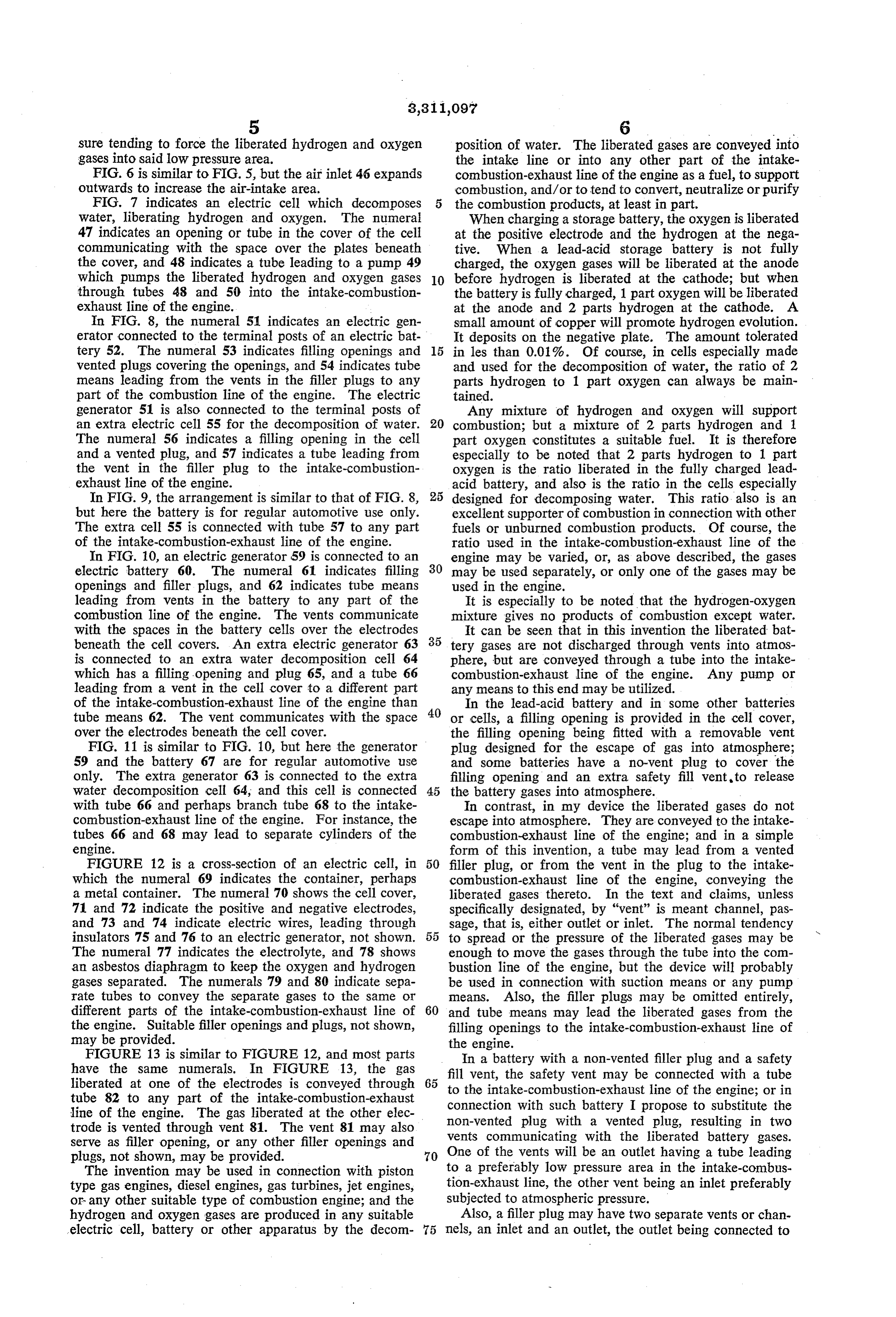
In the carburator, the battery gases will enrich the air-fuel liberating mixture and will produce a highly combustible vapor, hydrogen and oxygen. The numeral 43 in which will increase the efficiency of the engine. dicates an opening or tube in the cover of the cell com The tube 12 may also lead to the venturi of the car 70 municating with the space over the plates beneath the burator, perhaps to a point immediately downstream of cover. The numeral 44 indicates a tube conveying the the venturi throat, or may lead to any part of the intake liberated gases to a pressure area in the intake-combus line for enriching the air and fuel mixture. The tube 12 tion-exhaust line below atmospheric, and 45 indicates an may also be branched and connect to several parts or the air inlet into the cell, also communicating with the space intake line. 75 over the plates beneath the cover, the atmospheric pres
Page 7
Sure tending to force the liberated hydrogen and oxygen position of water. The liberated gases are conveyed into gases into said low pressure area. the intake line or into any other part of the intake FIG. 6 is similar to FIG. 5, but the air inlet 46 expands combustion-exhaust line of the engine as a fuel, to Support outwards to increase the air-intake area. combustion, and/or to tend to convert, neutralize or purify FIG. 7 indicates an electric cell which decomposes the combustion products, at least in part. Water, liberating hydrogen and oxygen. The numeral When charging a storage battery, the oxygen is liberated 47 indicates an opening or tube in the cover of the cell at the positive electrode and the hydrogen at the nega communicating with the space over the plates beneath tive. When a lead-acid storage battery is not fully the cover, and 48 indicates a tube leading to a pump 49 charged, the oxygen gases will be liberated at the anode which pumps the liberated hydrogen and oxygen gases 10 before hydrogen is liberated at the cathode; but when through tubes 48 and 50 into the intake-combustion the battery is fully charged, 1 part oxygen will be liberated exhaust line of the engine. at the anode and 2 parts hydrogen at the cathode. A In FIG. 8, the numeral 51 indicates an electric gen small amount of copper will promote hydrogen evolution. erator connected to the terminal posts of an electric bat It deposits on the negative plate. The amount tolerated tery 52. The numeral 53 indicates filling openings and 15 in les than 0.01%. Of course, in cells especially made vented plugs covering the openings, and 54 indicates tube and used for the decomposition of water, the ratio of 2 means leading from the vents in the filler plugs to any parts hydrogen to 1 part oxygen can always be main part of the combustion line of the engine. The electric tained.
generator 51 is also connected to the terminal posts of Any mixture of hydrogen and oxygen will support an extra electric cell 55 for the decomposition of water. 20 combustion; but a mixture of 2 parts hydrogen and 1 The numeral 56 indicates a filling opening in the cell part oxygen constitutes a suitable fuel. It is therefore and a vented plug, and 57 indicates a tube leading from especially to be noted that 2 parts hydrogen to 1 part the vent in the filler plug to the intake-combustion oxygen is the ratio liberated in the fully charged lead exhaust line of the engine. acid battery, and also is the ratio in the cells especially In FIG. 9, the arrangement is similar to that of FIG. 8, 25 designed for decomposing water. This ratio also is an but here the battery is for regular automotive use only. excellent supporter of combustion in connection with other The extra cell 55 is connected with tube 57 to any part fuels or unburned combustion products. Of course, the of the intake-combustion-exhaust line of the engine. ratio used in the intake-combustion-exhaust line of the In FIG. 10, an electric generator 59 is connected to an engine may be varied, or, as above described, the gases electric battery 60. The numeral 61 indicates filling 30 may be used separately, or only one of the gases may be openings and filler plugs, and 62 indicates tube means used in the engine.
leading from vents in the battery to any part of the It is especially to be noted that the hydrogen-oxygen combustion line of the engine. The vents communicate mixture gives no products of combustion except water. with the spaces in the battery cells over the electrodes It can be seen that in this invention the liberated bat beneath the cell covers. An extra electric generator 63 35 tery gases are not discharged through vents into atmos is connected to an extra water decomposition cell 64 phere, but are conveyed through a tube into the intake which has a filling opening and plug 65, and a tube 66 combustion-exhaust line of the engine. Any pump or leading from a vent in the cell cover to a different part any means to this end may be utilized. of the intake-combustion-exhaust line of the engine than In the lead-acid battery and in some other batteries tube means 62. The vent communicates with the space 40 or cells, a filling opening is provided in the cell cover, over the electrodes beneath the cell cover. the filling opening being fitted with a removable vent FIG. 11 is similar to FIG. 10, but here the generator plug designed for the escape of gas into atmosphere; 59 and the battery 67 are for regular automotive use and some batteries have a no-vent plug to cover the only. The extra generator 63 is connected to the extra filling opening and an extra safety fill vent to release water decomposition cell 64, and this cell is connected 45 the battery gases into atmosphere.
with tube 66 and perhaps branch tube 68 to the intake In contrast, in my device the liberated gases do not combustion-exhaust line of the engine. For instance, the escape into atmosphere. They are conveyed to the intake tubes 66 and 68 may lead to separate cylinders of the combustion-exhaust line of the engine; and in a simple engine. form of this invention, a tube may lead from a vented FIGURE 12 is a cross-section of an electric cell, in 50 filler plug, or from the vent in the plug to the intake which the numeral 69 indicates the container, perhaps combustion-exhaust line of the engine, conveying the a metal container. The numeral 70 shows the cell cover, liberated gases thereto. In the text and claims, unless 71 and 72 indicate the positive and negative electrodes, specifically designated, by "vent' is meant channel, pas and 73 and 74 indicate electric wires, leading through sage, that is, either outlet or inlet. The normal tendency insulators 75 and 76 to an electric generator, not shown. 55 to spread or the pressure of the liberated gases may be The numeral 77 indicates the electrolyte, and 78 shows enough to move the gases through the tube into the com an asbestos diaphragm to keep the oxygen and hydrogen bustion line of the engine, but the device will probably gases separated. The numerals 79 and 80 indicate sepa be used in connection with suction means or any pump rate tubes to convey the separate gases to the same or means. Also, the filler plugs may be omitted entirely, different parts of the intake-combustion-exhaust line of 60 and tube means may lead the liberated gases from the the engine. Suitable filler openings and plugs, not shown, filling openings to the intake-combustion-exhaust line of may be provided. the engine.
FIGURE 13 is similar to FIGURE 12, and most parts In a battery with a non-vented filler plug and a safety have the same numerals. In FIGURE 13, the gas fill vent, the safety vent may be connected with a tube liberated at one of the electrodes is conveyed through 65 to the intake-combustion-exhaust line of the engine; or in tube 82 to any part of the intake-combustion-exhaust connection with such battery I propose to substitute the line of the engine. The gas liberated at the other elec non-vented plug with a vented plug, resulting in two trode is vented through vent 81. The vent 81 may also vents communicating with the liberated battery gases. serve as filler opening, or any other filler openings and plugs, not shown, may be provided. 70 One of the vents will be an outlet having a tube leading The invention may be used in connection with piston to a preferably low pressure area in the intake-combus type gas engines, diesel engines, gas turbines, jet engines, tion-exhaust line, the other vent being an inlet preferably or any other suitable type of combustion engine; and the subjected to atmospheric pressure. hydrogen and oxygen gases are produced in any suitable Also, a filler plug may have two separate vents or chan electric cell, battery or other apparatus by the decom 75 nels, an inlet and an outlet, the outlet being connected to
Page 8
the intake-combustion-exhaust line of the engine and the 2. In a combustion engine having an intake-combus inlet preferably communicating with atmosphere. tion-exhaust line and an electric system, including an All these variations are part of this invention. Of electric generator connected to an electric cell comprising course, there are many more possible modifications of a vessel containing an electrolyte and positive and nega this device, and they all are included in this invention as tive electrodes disposed in the electrolyte, the electric cur related to means conveying the liberated battery gases to rent passing through the electrolyte decomposing water the intake-combustion-exhaust line of the engine. and liberating oxygen and hydrogen gases at the positive It is also to be noted that in this device, in connec and negative electrodes respectively, separate tubes con tion with the described air inlet, air is circulated through veying the liberated oxygen and hydrogen gases to the the space above the cell plates beneath the cell cover, 10 intake-combustion-exhaust line of the engine. thereby providing a cooling effect in the cell or battery. 3. In a system according to claim 2, separate tubes con This too forms part of this invention. veying the liberated oxygen and hydrogen gases to dif It is to be understood that fuel injection, or any other ferent parts of the intake-combustion-exhaust line of the fuel system may be used in connection with this device, engine.
and this forms part of this invention. 5 4. In a combustion engine having an intake-combus It is to be noted that the devices and features illustrated tion-exhaust line and an electric system, including an elec and described are interchangeable, and that various tric generator connected to an electric cell comprising a changes may be made within the spirit or scope of the vessel containing an electrolyte and positive and nega invention. tive electrodes disposed in the electrolyte, the electric In the text and claims, by "suction tube' is meant 20 current passing through the electrolyte decomposing water and liberating oxygen and hydrogen gases at the positive any tube which produces suction or is part of a suction and negative electrodes respectively, a tube conveying the - pump; by "inlet' is meant any means of ingress; by "out let' is meant any means of egress; by “cover' is also gas liberated at one of the electrodes to the intake-com meant filler plug or any other part forming the cell cover; bustion-exhaust line of the engine. by "engine' is meant internal combustion engine. 25
References Cited by the Examiner
The principles involved in this invention may be ap UNITED STATES PATENTS plied to all fields of combustion as related to the use of battery gases in the combustion line of an engine. 1,280,982 10/1918 Ford ------------ 136-180 X I claim: 1,363,889 12/1920 Linebarger --------- 136-161 1. In a combustions engine having an intake-combus 30 1,876,879 9/1932 Drabold ------------ 123-119 tion-exhaust line and an electric system including a gen 2,509,498 5/1950 Heyl ------------- 123-119 erator and a battery for normal automotive use, an ex 2,565,068 8/1951 Drabold ------------ 123-119 tra electric generator connected to an extra electric cell 2,687,448 8/1954 Gulick ----------- 136-177 comprising a vessel containing an electrolyte, positive and 2,687,449 8/1954 Gulick ------------- 136-177 negative electrodes disposed in the electrolyte, a cell cov 35 2,748,570 6/1956 Booth --------------- 60-97 er and a tube leading from the space over the electrolyte 2,988,589 6/1961 Osborn ------------ 136-179 beneath the cell cover to any part of the intake-combus 3,012,088 12/1961 Grady et al. ------ 136-180X tion-exhaust line of the engine; the electric current from 3,157,172 11/1964 Mittelstaedt -------- 123-119 the extra generator passing through the electrolyte in the extra electric cell decomposing water and liberating hy 40 MARK NEWMAN, Primary Examiner.
drogen and oxygen gases, said tube conveying the liber KARL ALBRECHT, Examiner.
ated gases to the intake-combustion-exhaust line of the engine. A. L. SMITH, Assistant Examiner.
Provenance
- Collection
- Cited prior art
- Original PDF
- patentimages.storage.googleapis.com →
- Filed
- 1964-11-24
- Pages
- 8
- Method
- pdftotext (the PDF's own text layer) + pdftoppm 300dpi page scans
- Source
- Google Patents bibliographic record
- Granted
- 1967-03-28
- Inventors
- Georg S Mittelstaedt
- Transcribed from
- patentimages.storage.googleapis.com →