patent · US4442801
Electrolysis fuel supplementation apparatus for combustion engines
17 April 1984
Page 1 — bibliographic record
United States Patent (19) 11 4,442,801 Glynn et al. 45 Apr. 17, 1984 54) ELECTROLYSS FUEL 4,023,545 5/1977 Mosher et al. ............. 123/DIG. 12 SUPPLEMENTATION APPARATUS FOR 4,084,938 4/1978 Willard, Sr. .......................... 44/1 G COMBUSTON ENGINES 4,124,463 11/1978 Blue ..................................... 204/129 76) Inventors: John D. Glynn, One Century Plz., Primary Examiner-William A. Cuchlinski, Jr. 2029 Century Park East, Los Attorney, Agent, or Firm-Fulwider, Patton, Rieber, Angeles, Calif. 90067; Daniel R. Lee & Utecht
Glynn, 2215 El Arbolito Dr., 57 ABSTRACT
Glendale, Calif. 91208; Arthur R. A combustion engine is provided with a fuel supple
Andrews, 1049 Alcalde Dr., mentation system in which water is broken down by
Glendale, Calif. 91207 electrolysis into hydrogen and oxygen which are then (21) Appl. No.: 331,246 added to the fuel delivery system. The electrolysis takes 22 Filed: Dec. 16, 1981 place in a chamber in which a pusher gas rises through perforated horizontal electrode plates to sweep the (51) Int. Cl. .............................................. FO2B 43/10 hydrogen and oxygen from the plates as it is generated, 52 123/3; 123/DIG. 12 thereby preventing the accumulation of these gases in (58) Field of Search .................. 123/1 A, 3, DIG. 12; the chamber. In addition, the electrolyte can be circu 204/129 lated, passing it through a filter, to increase the turbu 56 References Cited lence and agitation within the chamber. The rate at
lating the voltage applied to the plates, in accordance 1,333,836 3/1920 Csanyl ................................. 204/129 with the throttle position of the engine. Since gases do 1,379,077 5/1921 Blumberg, Jr. 123/DIG. 12 not accumulate in the chamber, variations in the rate at 1,876,879 9/1932 Drabold .............................. 123/527 which these gases are yielded are affected substantially 2,006,676 7/1935 Garrett .................................... 204/5 instantaneously. Lignite activited water can be added to 2,509,498 5/1950 Heyl .................................... 123/525 2,937,634 5/1960 Kelseaux et al. 123/DIG. 12 the electrolyte to inhibit the formation of sludge.
3,648,668 3/1972 Pacheco .................................. 123/3 25 Claims, 5 Drawing Figures
conve surca as
Page 2
Drawing sheet — no readable text.
Page 3
Nessess SS N
NaN NaNNNAN
Yun
a. SSasasas
arzzzzzzzzzzzzzzzzzzzzzzzzzzzze SaaaaaSYYYYYYYYYYYAase
Naarn,
a Na Na NaSNS Na N E. NYN
S NSNSSSSSSSSSSSSSSSSSN
NNN
MYS SSSSSSaaS.SYSYNAanana Nalays
ANY
YaNYYAASSNANAANNA
2 N to sel/ ;: " ' W
Page 4
Drawing sheet — no readable text.
Page 5
Drawing sheet — no readable text.
Page 6
impact, such as a collision of a vehicle in which the
ELECTROLYSS FUEL SUPPLEMENTATION system is in use.
APPARATUS FOR COMBUSTON ENGINES A still further problem associated with such electro lytic hydrogen supplementation systems is that sludge'
FIELD OF THE INVENTION tends to accumulate in the chamber. The electrode The present invention relates to engines and, more surfaces may become coated and orifices may be particularly, to engines that employ a hydrogen supple clogged.
mented fuel supply. An objective of the present invention is the provision BACKGROUND OF THE INVENTION 10 tema that of new and improved hydrogen supplementation sys overcomes or minimizes the above-mentioned
Hydrogen has numerous important advantages as a disadvantages of previously known systems. fuel. The energy released per pound is high when com SUMMARY OF THE INVENTION pared to conventional fuels and it is clean-burning.
Moreover, it can be burned in a conventional spark 15 The present invention accomplishes the above objec ignition, internal combustion engine. tive by the use of a fuel supplementation system in There are, however, serious drawbacks to the use of which hydrogen and oxygen are generated, on demand, hydrogen that have prevented its adoption as a common in an electrolysis chamber, and these gases are con engine fuel. Among the most important of its drawbacks stantly swept from electrode plates on which they is its extreme volatility, creating an ever present danger 20 would otherwise accumulate. Delivery of the supple of an accidental ignition and explosion. In addition, ment gases to the combustion chamber of the engine is hydrogen must be stored at high pressures in heavy substantially instantaneous. The rate at which hydrogen gauge tanks and its pressure varies widely with changes and oxygen are generated is varied in response to the in temperature. To reduce the pressure of stored hydro engine throttle setting, as by modulating the voltage gen to a level at which it can be introduced into the fuel 25 applied to the electode plates. Preferably, the electrode delivery system of an internal combustion engine gener plates are horizontal and perforated, the plates of one ally requires an elaborate arrangement of valves and electrode being interleaved with those of the opposite heat exchangers. electrode. A pusher gas may be introduced at the bot Recognizing the advantages of hydrogen as a pri tom of the electrolysis chamber to sweep the plates, this mary fuel, particularly in the case of motor vehicle 30 gas being distributed along the bottom of the chamber power plants, there has been some experimentation to by a perforated pusher gas manifold. The pusher gas evaluate its practical utility as a fuel supplement. It has can advantageously be a portion of the engine exhaust been found that when hydrogen is mixed with gasoline that is to be recirculated. and air in the combustion chamber of a spark-ignition Sweeping of the electrode plates can also be affected engine, it results in improved combustion. The advan-3s by circulating the electrolyte, which can be passed tages gained are believed to result from the ability of through a filter as it circulates. The electrolyte can be hydrogen to sustain combustion at lean mixtures, with returned to the electrolysis chamber by a perforated reduced combustion temperatures. The result is sub circulation manifold that can be internested with the stantially improved thermal efficiency and a marked pusher gas manifold along the bottom of the chamber. reduction of noxious emissions. The fuel supplement gases are supplied to the air/fuel The use of hydrogen as a fuel supplement, however, intake of the carburetor or other fuel delivery means of presents the same difficulties as its use as a primary fuel, the engine. Any gases not drawn into the engine are although on a smaller scale. It has, therefore, been pro allowed to escape and dissipate into the atmosphere. posed to generate the hydrogen at the engine by elec trolysis of water. Oxygen is also yielded by the electrol 45 performance of the device can The electrode surfaces be kept clean and the enhanced by the addition of ysis to further enhance combustion. While this arrange lignite activited water to the electrolyte. A reservoir is ment has confirmed certain theoretical advantages of provided from which the electrolyte is supplied to the hydrogen supplementation, it has, apparently, not chamber in response to a signal indicating a reduction in yielded a practical, workable system, as the arrange ment has been known for some time but has not come 50 the electrolyte level.
into common use. Other features and advantages of the present inven It is believed that a principal reason for the lack of tion will become apparent from the following detailed practical workability of previously known hydrogen description, taken in conjunction with the accompany supplementation systems is that the hydrogen and oxy ing drawings, which illustrate, by way of example, the gen gases tend to accumulate on the surfaces of the 55 principles of the invention.
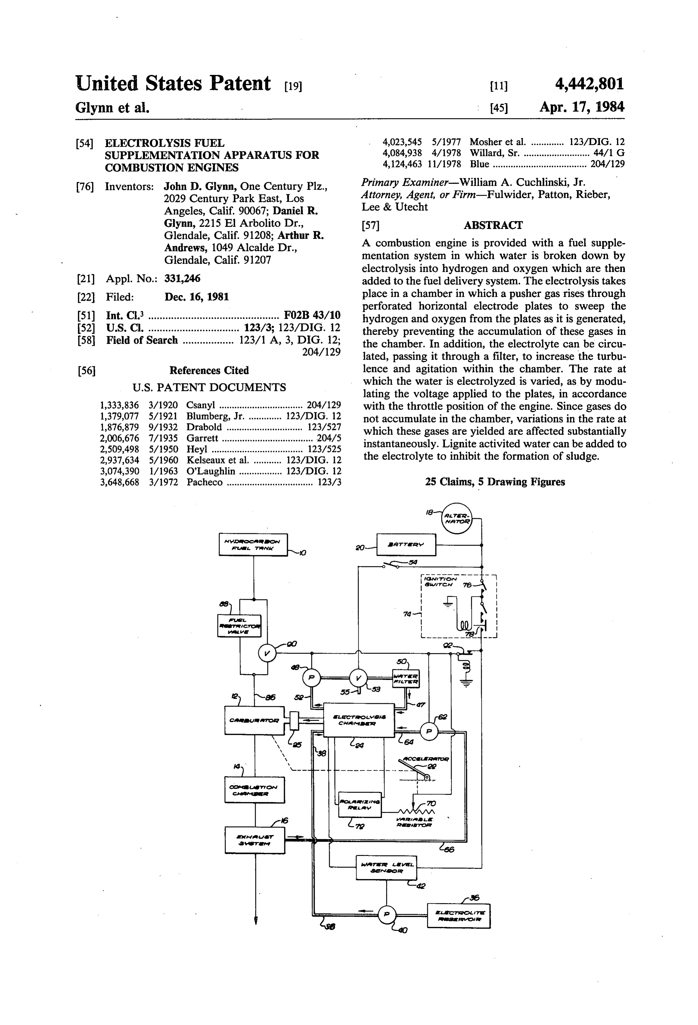
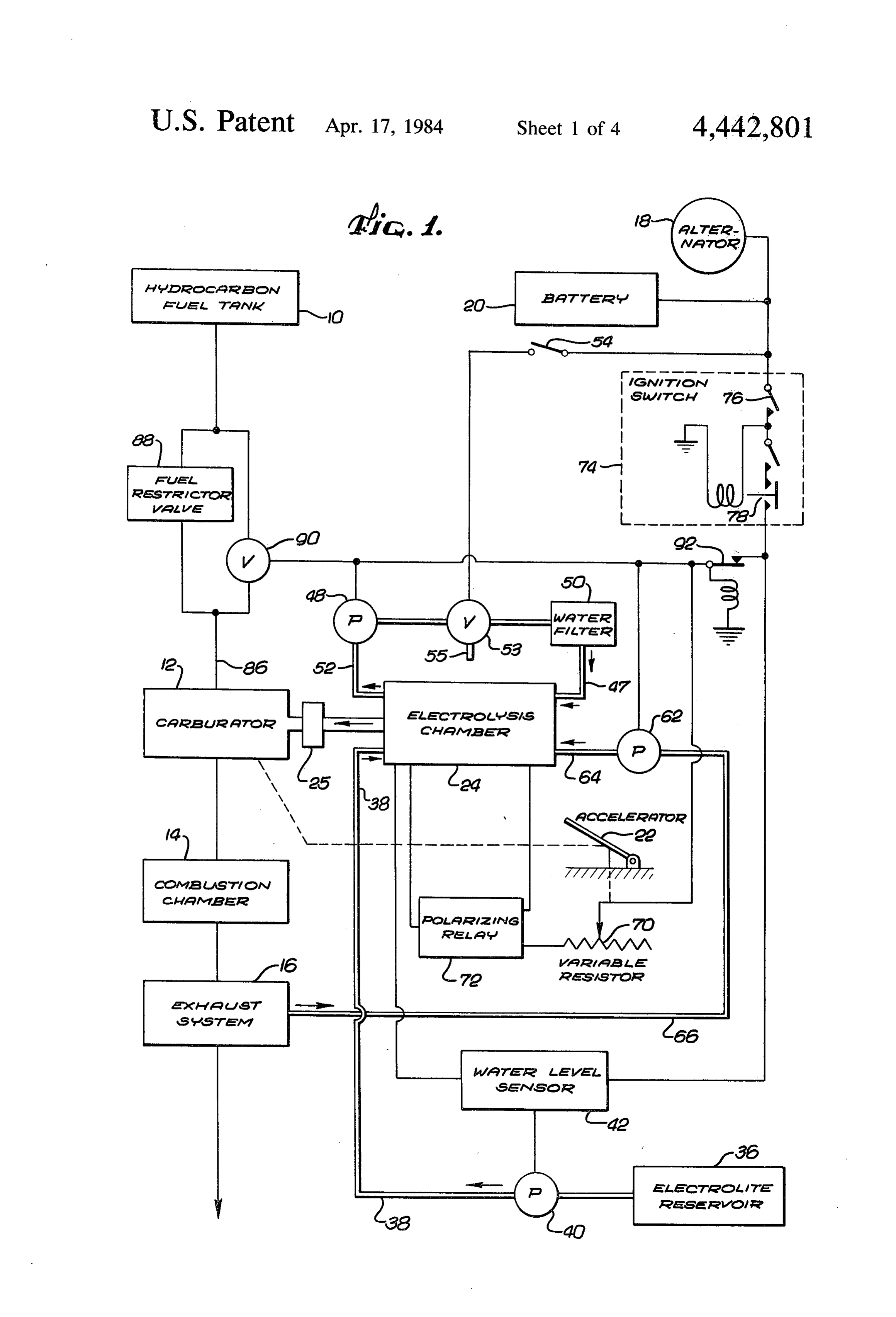
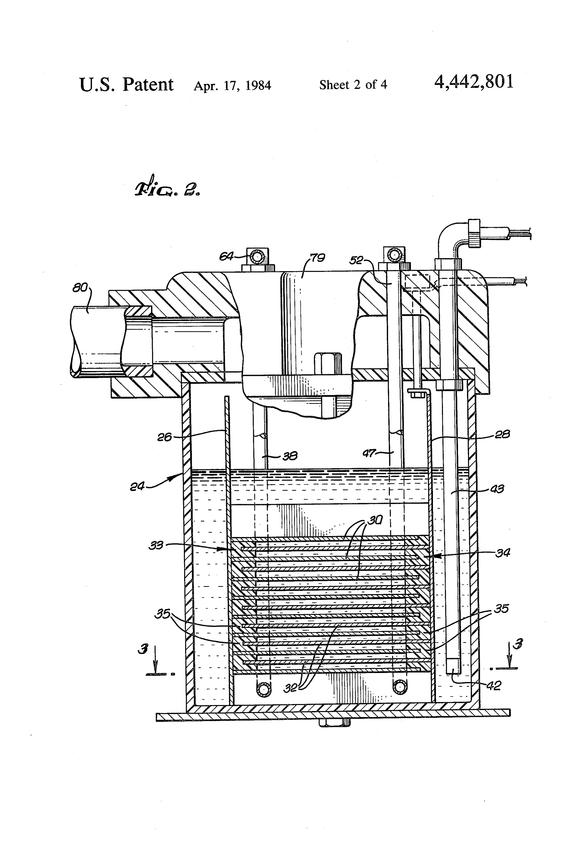
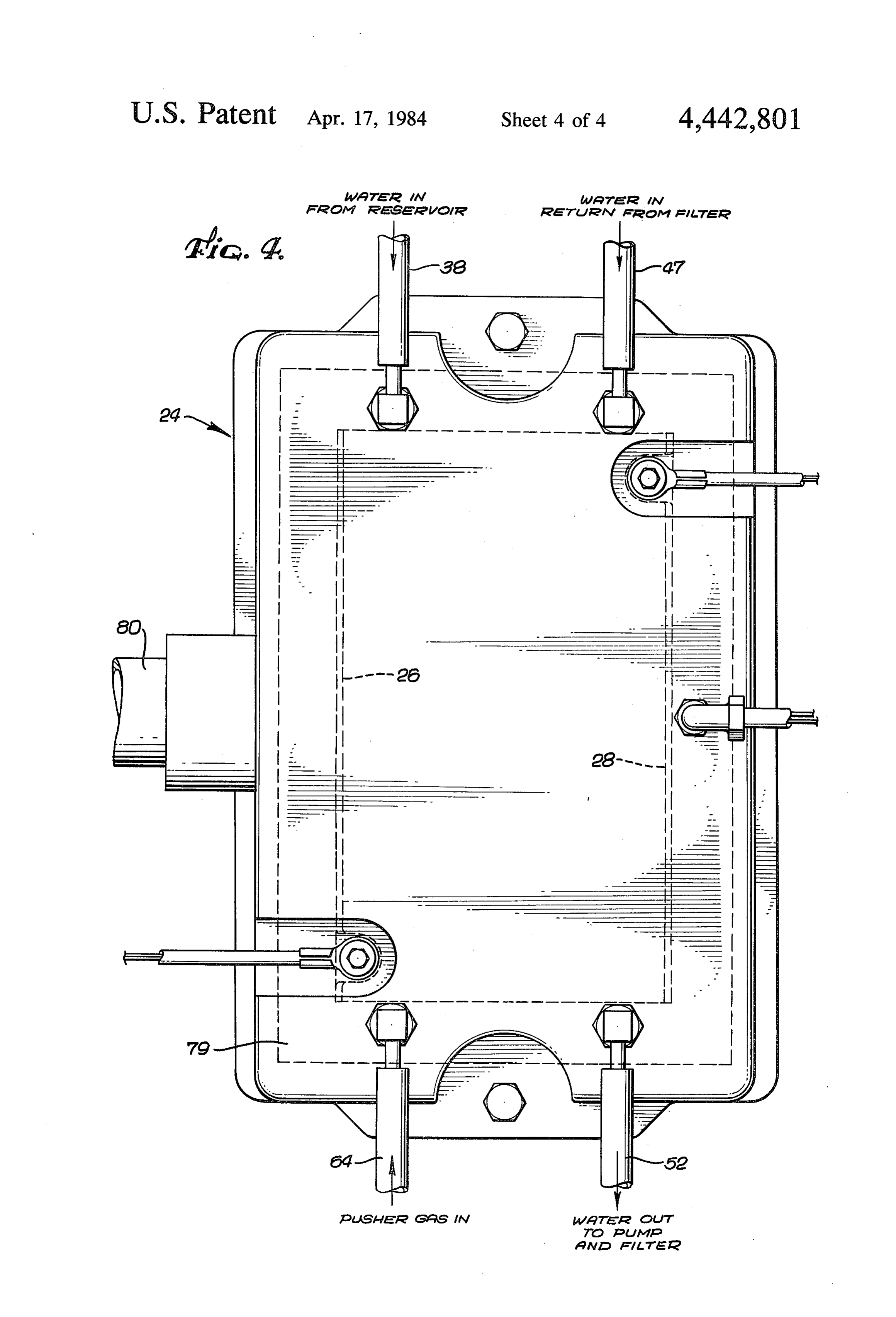
electrode plates by which the water is broken down. BRIEF DESCRIPTION OF THE DRAWINGS The accumulated gases reduce the effectiveness of the FIG. 1 is a schematic illustration of an internal com apparatus by temporarily preventing large portions of the electrode surfaces from interacting with the electro bustion engine that includes a fuel supplementation lyte. A cyclical or erratic yield of hydrogen and oxygen 60 apparatus constructed in accordance with the present may result. invention:
Another and perhaps more important problem is that FIG. 2 is a cross-sectional end view of an electrolysis the accumulation of the hydrogen and oxygen gases in chamber of the apparatus of FIG. 1;
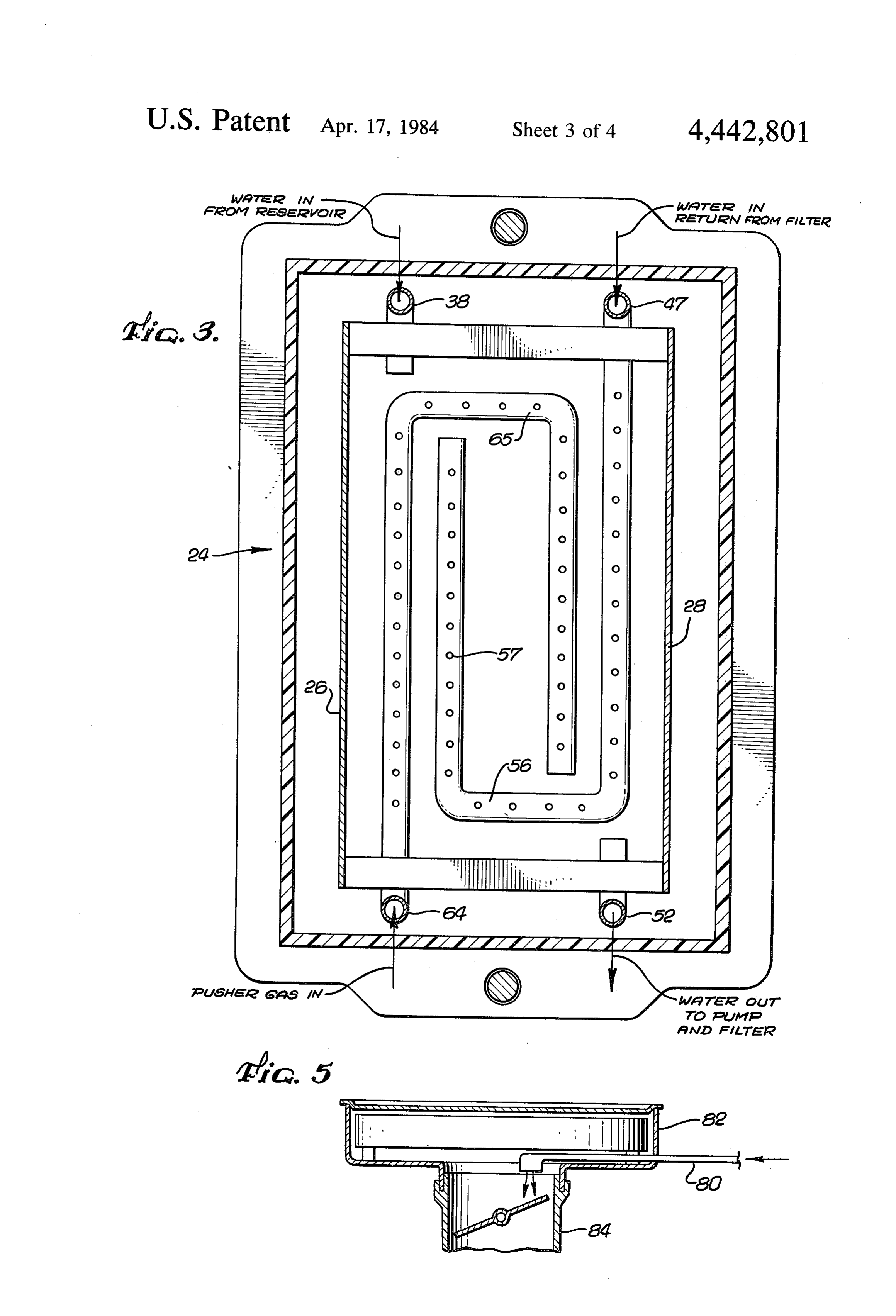
the electrolysis chamber prevents the quality of such FIG. 3 is a cross-sectional top view of the electrolysis gases produced from being responsive to the instanta 65 chamber taken along the line 3-3 of FIG. 2; neous demand. In addition, the accumulation of these FIG. 4 is a top view of the electrolysis chamber; and highly volatile gases presents a safety hazard since the FIG. 5 shows the input of the fuel supplement to the accumulated gases would be released in the event of an carburetor of the engine.
Page 7
rectangular strip. It must be made of a non-conductive
DESCRIPTION OF THE PREFERREED material and must withstand chemical attack at elevated EMBODIMENT temperatures by the electrolyte and the gases present in The invention will be explained with reference to an the chamber 24. Many materials commonly used as exemplary embodiment, shown in FIGS. 1 through 5, spacers in batteries are not satisfactory. Thus, oak and that is applied to a conventional spark-ignition, internal even cetain ceramics are to be avoided. Glass is pre combustion engine of the reciprocating type. It is as ferred.
sumed that fuel, preferably gasoline from a hydrocar The electrolyte is supplied to the electrolysis cham bon fuel tank 10 is supplied to a conventional carburetor ber 24 from a remote electrolyte reservoir 36 (FIG. 1) through a fill pipe 38. Water possessing sufficient impu 12 where it is mixed with ambient air and delivered to 10 one or more combustion chambers 14. Exhaust gases rities to promote ionization is a suitable electrolyte. In exit from the engine through an exhaust system 16. The most cases ordinary tap water will do. However, supe above engine components are shown schematically in rior performance is obtained by the use of an electrolyte FIG. 1. additive known as catalyst altered water or lignite ac The mechanical power output of the engine drives an 15 tiviated water. The additive contains sodium, potas electrical alternator 18 which charges a battery 20 and sium, silicates and the aqueous solution lignite, de energizes the ignition system (not shown) of the engine. scribed in U.S. Pat. Nos. 3,893,943 and 4,084,938 to A throttle 22 is connected to the carburetor 12 to con Willard. It is beneficial because it inhibits the formation trol the speed of the engine in the conventional manner. of sludge in the chamber 24 and prevents the apparatus Performance and efficiency of the engine are im 20 from becoming clogged.
proved substantially by the addition of a fuel supple The electrolyte is pumped from the reservoir 36 by a mentation apparatus, the heart of which is an electroly supply pump 40 that is electrically actuated by an elec sis chamber 24, as shown in greater detail in FIGS. 2, 3 trolyte level sensor 42 in the chamber 24. The sensor 42 and 4. In this chamber 24, hydrogen and oxygen are takes the form of a pressure responsive switch mounted generated by the electrolysis of water for addition to 25 on the bottom end of a rod 43 positioned vertically the fuel introduced through a fire brake 25 to the engine within the chamber 24 (FIG. 2). Thus, as the electrolyte combustion chambers 14. in the electrolysis chamber 24 is consumed, it is always The electrolysis chamber 24 is formed by a water maintained at such a level that the electrode plates 30 proof, generally box-like, seamless casing made of a and 32 are fully submerged.
chemically and electrically inert material such as tem 30 The electrolyte is continuously withdrawn from the pered glass, high density and high impact plastic, a bottom of the chamber 24 through a tube 47 (shown in glazed ceramic or a lava product. As best shown in FIGS. 2 and 3) by a circulation pump 48 and returned FIG. 2, two oppositely charged, imperforate, rectangu through a filter 50 to a tube 52 that likewise lies at the lar electrode members 26 and 28 are vertically disposed bottom of the chamber. The filter 50 prevents the along opposite sides of the chamber 24. A first set of 35 buildup of sludge that tends to collect in the electrolysis horizontal, rectangular electrode plates 30 extends from chamber 24, coating the electrodes 33 and 34 and reduc the first vertical electrode member 26 toward the sec ing the efficiency of the apparatus. Ideally, the filter 50 ond electrode member 28. These plates 30 are in electri should remove rust particles but allow rust to remain in cal contact with the first vertical member 26 but are not solution in the electrolyte to serve as a conductor. A in electrical contact with the second vertical member being 10-50 micron filter is desirable, with a 10 micron filter 28. A second set of similar plates 32 extends horizon preferred.
tally from the second vertical electrode member 28 As the electrolyte flows from the circulation pump 48 toward the first member 26 and are in electrical contact to the chamber 24, it passes through a valve 53 which with the second member but not the first. normally occupies a flow-through position. The valve The plates 30 and 32 of the first and second sets are 45 53 can, however, be repositioned, by closing an electri interleaved. Thus, the first vertical electrode member cally operated switch 54, causing the output of the 26 and the first set of plates 30 combine to form a single pump 48 to be diverted to an outlet 55 instead of reach electrode 33 of one polarity while the second vertical ing the chamber 24 (FIG. 1). Thus, the circulation electrode member 28 and the second set of plates 32 pump 48 can be used to empty the electrolysis chamber combine to form a second electrode 34 of the opposite 50 24, which is desirable if the electrolyte becomes con polarity. taminated or if the temperature is expected to drop The electrode plates 30 and 32 are perforated to per below freezing. .
mit an electrolyte to flow through and between them When the pump 48 is operating, with the valve 53 with the holes of successive plates being non-aligned to closed, a constant circulation of the electrolyte is main promote agitation of the electrolyte as it flows and to: 55 tained to inhibit the accumulation of hydrogen-oxygen enhance lateral electrolyte flow. A preferred electrode gas on the surfaces of the plates 30 and 32 that would material is stainless steel of the 300 series. It has been occur if the electrolyte were relatively static. The accu found advantageous to use perforations of 5/32 of an mulation of these gases would shield portions of the inch at a density of 33 per square inch, which results in plate surfaces from the electrolyte and effectively pre the removal of 63 percent of the plate material, al vent those portions from engaging in the electrolysis though it will be appreciated that other configurations process, thus reducing the quantity of hydrogen pro are suitable. duced.
It is important to maintain the spacing between the It is important to promote substantially uniform agita electrode plates 30 and 32 and to prevent oppositely tion of the electrolyte throughout the electrolysis cham charged adjacent plates from contacting each other. 65 ber 24. A circulation manifold portion 56 of the tube 52 For this reason, spacers 35 are inserted between adja within the chamber 24, therefore, extends horizontally cent plates 30 and 32 along the two vertical electrode first lengthwise along the chamber, then along the op members 26 and 28. Each spacer 35 is an elongated posite end of the chamber and finally back toward the
Page 8
first end, thus being generally U-shaped (see FIG. 3). trols a solenoid operated switch 78 through which the Perforations 57 along the top surface of the manifold 56 larger current to the electrolysis chamber 24 flows. permit the returning electrolyte to escape from this The hydrogen and oxygen that rise to the top of the closed-end structure as it flows in an upward direction. electrolysis chamber 24, along with the pusher gas from Horizontal disposition of the electrode plates 30 and the pump 62, is collected by a hood 79 that forms the 32 is desirable in part because it promotes the greatest top of the chamber as shown in FIGS. 2 and 4. The gas agitation of the plate surfaces due to the circulating then exits at one side of the hood 79 through a conduit electrolyte. However, the presence of downwardly 80 to the carburetor 12. At the carburetor 12 the gases facing electrode surfaces also tends to have the effect of holding the buoyant hydrogen and oxygen bubbles as 10 from the electrolysis chamber 24 are introduced di rectly to the center of an air cleaner 82 above an intake they form. It is, therefore, beneficial to the performance 84 of the carburetor itself, as shown in FIG. 5. of the hydrogen generation system to provide for Passing these gases through the carburetor 12 insures greater turbulence within the chamber 24. Increased thorough mixing with the new gasoline, supplied by a agitation is provided by a pusher gas pump 62 by which gas line 86, and any ambient air which is drawn in to a pusher gas is forced through a line 64 under pressure 15 supplement the gas from the electrolysis chamber 24. In to the bottom of the chamber 24 so that the gas rising up the event that the fuel delivery system of the engine is through the chamber will dislodge hydrogen-oxygen by fuel injection instead of carburation, the conduit 80 bubbles that have collected on the electrode surfaces.
As it rises, the pusher gas is confined between the verti from the electrolysis chamber 24 is simply positioned cal electrode members 26 and 28. 20 adjacent to the air intake of the injection system (not A perforated manifold portion 65 of the line 64 shown). This arrangement also permits escape into the atmo through which the pusher gas is released into the cham sphere ber 24 is arranged horizontally along the bottom of the into theofcarburetor any hydrogen and oxygen that is not drawn chamber to complement the action of the circulating result of low engineordemand other fuel delivery system as the electrolyte released through the circulation manifold 25 and oxygen is produced. It is atthus the time the hydrogen an advantage of the 56. It has a U-shaped configuration oppositely oriented invention that no hydrogen or oxygen with respect to the circulation manifold 56, so that the the system. Hydrogen is produced on demand is ever stored in two manifolds 56 and 65 are internested in a rectangular used it is immediately dissipated. The quantityand if not of gases format as shown in FIG. 3.
The pusher gas should be a gas that would otherwise 30 dissipated is minimized because gases cannot accumu be introduced through the carburetor 12 and, therefore, late in the electrolysis chamber 24 in substantial quanti will not affect the combustion process apart from the ties.Because the demands of the engine for hydrocarbon presence of the hydrogen and oxygen yielded by the electrolysis chamber 24. This gas can be ambient air. It fuel are significantly reduced when the hydrogen sup is preferred, however, as shown in FIG. 1, to use a 35 plementation system is in operation, a manually adjust portion of the engine exhaust diverted from the exhaust able fuel restrictor valve 88 is inserted in the gasoline system 16 via a tube 66. The gas includes a large compo line 86. However, this restrictor 88 is bypassed when nent of unburned hydrocarbons that must be recycled the hydrogen supplementation system is not in use by to control pollution. The hydrogen supplementation allowing the gasoline to flow through an electrically system then serves a dual function by recycling the controlled valve 90. When the hydrogen supplementa exhaust gases and by assuring that these exhaust gases, tion system is activiated by closing a switch 92, the that commonly contribute to poor engine performance, valve 90 is turned to a position in which it blocks the are thoroughly mixed with the hydrogen and oxygen so flow of any gasoline that would bypass the restrictor 88. that they are burned as fully and completely as possible. It will be appreciated that the invention provides for The electric power that must be applied to the elec 45 a substantial improvement in the performance of an trodes 33 and 34 is derived from the alternator 18, internal combustion engine with relatively little change driven by the engine itself, and from the battery 20 in or modification to the engine itself. In fact, the system the event that sufficient power is not available from the requires little or no modification of the engine and it can alternator. The voltage from the alternator 18 and the be easily added to existing engines. The system can be battery 20 is modulated by a variable resistor 70 or other 50 removed from one engine and installed on another and voltage attenuation device mechanically operated by the engine can be readily returned to its original condi the throttle 22 (FIG. 1). Accordingly, the rate at which tion. It has been found to very significantly increase the hydrogen is generated in the electrolysis chamber 24 is power and economy of the engine, also causing it to run controlled by modulating the plate potential in accor more smoothly, and it greatly decreases the emission of dance with the instantaneous power demands made 55 pollutants.
upon the engine by manually adjusting the position of While a particular form of the invention has been the throttle 22. illustrated and described, it will be apparent that various As the current passes from the variable resistor 70 to modifications can be made without departing from the the electrodes 33 and 34, it passes through a polarizing spirit and scope of the invention.
relay 72. The purpose of this relay 72 is to reverse the 60 We claim:
polarities of the electrodes 33 and 34 each time that an 1. In a combustion engine including at least one com ignition switch 74 is returned to the "on' position. This bustion chamber, a hydrocarbon fuel tank, fuel delivery periodic reversal of polarity prevents the buildup of means for mixing said fuel with air and delivering said solid deposits on the electrode surfaces and reduces any fuel/air mixture to said combustion chamber, throttle tendency of those surfaces to be damaged chemically by 65 means for adjustably controlling said fuel delivery the electrolysis process. The ignition switch 74 actually means, and a source of electrical potential energized by includes two switches. A manually operated switch 76, the operation of said engine, the improvement to said which has a low current carrying capacity, in turn con engine comprising:
Page 9
a reservoir containing an electrolyte that is at least valve means to admit additional electrolyte to said part water; chamber in response to a reduction in said level. an electrolysis chamber; 11. The apparatus of claim 10 wherein said sensor an electrolyte feed line leading from said reservoir to means comprises a pressure responsive switch. said chamber, whereby said chamber is filled with 5 12. In a combustion engine, including at least one said electrolyte; combustion chamber, a hydrocarbon fuel tank, fuel a pair of electrodes disposed within said chamber and delivery means for mixing said fuel with air and deliver at least partially immersed in said electrolyte, each ing said fuel/air mixture to said combustion chamber, of said electrodes including a plurality of perfo 10 throttle means for adjustably controlling said fuel deliv ery means, a source of electrical potential energized by rated horizontal electrode plates, said electrodes the operation of said engine and an exhaust system for being electrically connected to opposite sides of removing exhaust gases from said engine, the improve said source of electrical potential, whereby said ment to said engine comprising: electrolyte is broken down to yield hydrogen and a reservoir containing an electrolyte that is at least Oxygen;
voltage means for varying the electrical potential 15 anpart water;
electrolysis chamber;
applied to said electrode plates in response to ad an electrolyte feed line leading from said reservoir to justment of said throttle means thereby producing said chamber whereby said chamber is filled with hydrogen and oxygen at a rate responsive to the electrolyte;
adjustment of said throttle means; 20 a pair of electrodes disposed within said chamber and fuel supplement delivery means for supplying said at least partially immersed in said electrolyte, said hydrogen and oxygen to said fuel delivery means; electrodes being electrically connected to opposite pump means for blowing a pusher gas under positive sides of said source of electrical potential, whereby pressure through a pusher gas manifold, whereby said electrolyte is broken down to yield hydrogen said gas rises through said chamber and sweeps said 25 and oxygen;
hydrogen and oxygen from said plates; and fuel supplement delivery means for supplying said a perforated pusher gas manifold extending through hydrogen and oxygen to said fuel delivery means; out the entire bottom of said chamber beneath said return pump means for recirculating a portion of said electrodes to distribute said pusher gas horizontally exhaust gas from said exhaust system; and throughout the bottom of said chamber whereby 30 means for supplying said portion of said exhaust gases said pusher gas instantaneously sweeps hydrogen from said return pump means to said electrolysis and oxygen from said plates and prevents a hazard chamber beneath said electrodes as a pusher gas, ous and unsafe accumulation of hydrogen and oxy whereby said pusher gas rises through said electro gen within said chamber. lyte and sweeps said hydrogen and oxygen from 2. The apparatus of claim 1 wherein the plates of said 35 said electrodes.
electrodes are interleaved. 13. The apparatus of claim 12 wherein each of said 3. The apparatus of claim 2 wherein said perforations electrodes comprises a plurality of horizontal plates, the of alternate ones of said plates are non-aligned to pro plates of said electrodes being interleaved. mote lateral movement of said pusher gas. 14. The apparatus of claim 13 wherein each of said 4. The apparatus of claim 3 wherein successive ones plates has perforations therein to allow said pusher gas of said plates are vertically separated by non-conduc to rise through said perforations. w tive spacers. 15. The apparatus of claim 12 further comprising: 5. The apparatus of claim 4 wherein said spacers are valve means for selectively permitting said electro elongated glass strips. lyte to flow from said reservoir into said electrolyte 6. The apparatus of claim 1 further comprising circu 45 chamber; and lation means for causing said electrolyte to circulate means for sensing the level of electrolyte in said elec through said electrolysis chamber, thereby enhancing trolysis chamber and for causing said valve means the movement of hydrogen and oxygen away from said to admit additional electrolyte to said chamber in plates. response to a reduction in said level. 7. The apparatus of claim 6 wherein said circulation 50 16. The apparatus of claim 12 further comprising means includes a pump. circulation means for causing said electrolyte to circu 8. The apparatus of claim 1 further comprising circu late through said electrolysis chamber, thereby promot lation means for causing said electrolyte to circulate ing the movement of hydrogen and oxygen from said through said electrolysis chamber, said circulation plates. . . . .. . means comprising a pump and a filter arranged in series. 55 17. The apparatus of claim 12 further comprising 9. The apparatus of claim 1 wherein said fuel delivery circulation means for causing said electrolyte to circu means of said engine has an air/fuel intake, said fuel late through said electrolyis chamber, said circulation supplement delivery means supplying said hydrogen means comprising a pump and a filter arranged in series. and oxygen from said electrolysis chamber to said in 18. The apparatus of claim 12 wherein said fuel deliv take and any hydrogen and oxygen not drawn into said ery means of said engine has an air/fuel intake, said fuel fuel delivery means being allowed to escape into the supplement delivery means supplying said hydrogen atmosphere. and oxygen from said electrolysis chamber to said in 10. The apparatus of claim 1 further comprising: take and any hydrogen and oxygen not drawn into said valve means for selectively permitting said electro fuel delivery means being allowed to escape. lyte to flow from said reservoir into said electroly 65 19. The apparatus of claim 12 further comprising sis chamber; and . . . . ." means for varying the rate at which said electrolyte is sensor means for sensing the level of said electrolyte broken down in response to the adjustment of said in said electrolysis chamber and for causing said throttle means.
Page 10
20. The apparatus of claim 12 further comprising ing said fuel/air mixture to said combustion chamber, voltage means for varying the electrical potential ap throttle means for adjustably controlling said fuel deliv plied to said electrode plates in response to the adjust ery means, and a source of electrical potential energized ment of said throttle means. by the operation of said engine, the improvement to said 21. A combustion engine including at least one com 5 engine comprising:
bustion chamber, a hydrocarbon fuel tank, fuel delivery a reservoir containing an electrolyte that is at least means for mixing said fuel with air and delivering said part water;
fuel/air mixture to said combustion chamber, and a an electrolysis chamber; source of electrical potential energized by the operation an electrolyte feed line leading from said reservoir to of said engine, the improvement to said engine compris 10 said chamber, whereby said chamber is filled with 1ng: said electrolyte;
a reservoir containing a liquid electrolyte that is at a pair of electrodes disposed within said chamber and least part water; at least partially immersed in said electrolyte, each an electrolysis chamber; of said electrodes including a plurality of perfo an electrolyte feed line leading from said reservoir to 15 rated horizontal electrode plates, said electrodes said chamber whereby said chamber is filled with being electrically connected to opposite sides of said electrolyte;
a pair of electrodes disposed within said chamber and said source of electrical potential, whereby said at least partially immersed in said electrolyte, said electrolyte is broken down to yield hydrogen and electrodes being electrically connected to opposite 20 Oxygen;
sides of said source of electrical potential, whereby voltage means for varying the electrical potential said electrolyte is broken down to yield hydrogen applied to said electrode plates in response to ad and oxygen; justment of said throttle means thereby producing fuel supplement delivery means for supplying said hydrogen and oxygen at a rate responsive to the hydrogen and oxygen to said fuel delivery means; 25 adjustment of said throttle means; and fuel supplement delivery means for supplying said circulation means for causing said liquid electrolyte hydrogen and oxygen to said fuel delivery means; to be removed from and returned to said electroly pump means for blowing a pusher gas under positive sis chamber, thereby increasing the turbulence and pressure through a pusher gas manifold, whereby agitation within said chamber to instantaneously 30 said gas rises through said chamber and sweeps said sweep hydrogen and oxygen from said electrodes hydrogen and oxygen from said plates; and prevent a hazardous and unsafe accumulation a perforated pusher gas manifold extending through of hydrogen and oxygen within said chamber. out the entire bottom of said chamber beneath said 22. The apparatus of claim 21 wherein each of said electrodes to distribute said pusher gas horizontally electrodes comprises a plurality of horizontal plates, the 35 throughout the bottom of said chamber whereby plates of said electrodes being interleaved. said pusher gas instantaneously sweeps hydrogen 23. The apparatus of claim 22 wherein each of said and oxygen from said plates and prevents a hazard plates has perforations therein to allow said pusher gas ous and unsafe accumulation of hydrogen and oxy to rise through said perforations. gen within said chamber; and 24. The apparatus of claim 22 wherein said electro circulating means for causing said electrolyte to cir lyte includes lignite activited water. culate throughout said chamber, thereby enhanc 25. In a combustion engine including at least one ing the movement of hydrogen and oxygen from combustion chamber, a hydrocarbon fuel tank, fuel each of said plates simultaneously. delivery means for mixing said fuel with air and deliver k is a k sk
Provenance
- Collection
- Cited prior art
- Original PDF
- patentimages.storage.googleapis.com →
- Filed
- 1981-12-16
- Pages
- 10
- Method
- pdftotext (the PDF's own text layer) + pdftoppm 300dpi page scans
- Source
- Google Patents bibliographic record
- Granted
- 1984-04-17
- Inventors
- John D. Glynn; Daniel R. Glynn; Arthur R. Andrews
- Transcribed from
- patentimages.storage.googleapis.com →