patent · US20020179454A1
Electrolysis cell and internal combustion engine kit comprising the same
5 December 2002
Page 1 — bibliographic record
(19) United States (12) Patent Application Publication (10) Pub. No.: US 2002/0179454 A1
ROSS (43) Pub. Date: Dec. 5, 2002 (54) ELECTROLYSIS CELL AND INTERNAL (30) Foreign Application Priority Data
COMBUSTION ENGINE KIT COMPRISING
THE SAME Jun. 4, 2001 (CA).......................................... 2,349,508 Publication Classification (75) Inventor: Bill Ross, Newmarket, CA (US) (51) Int. Cl." .............................. C25C 3700; C25B 9/00;
Correspondence Address: (52) U.S. Cl. ......................... 205/637; 205/633; 205/335;
VIDAS, ARRETT & STEINKRAUS, PA.
6109 BLUE CIRCLE DRIVE (57) ABSTRACT
SUTE 2000 A System for producing one or more gases for enhancing MINNETONKA, MN 55343-9185 (US) combustion in an internal combustion engine, the engine having an intake, the System comprising: an electrolysis cell, (73) Assignee: Global Tech Environmental Products for generating one or more combustion enhancing gases Inc., Aurora (CA) under preSSure, a gas conduit, for connecting the electrolysis cell to the internal combustion engine; and a flow regulator, (21) Appl. No.: 10/162,367 operatively connected between the electrolysis cell and the intake of the engine, for regulating a flow of the combustion (22) Filed: Jun. 3, 2002 enhancing gases to the engine.
Page 2
Drawing sheet — no readable text.
Page 3
Drawing sheet — no readable text.
Page 4
Drawing sheet — no readable text.
Page 5
Drawing sheet — no readable text.
Page 6
Drawing sheet — no readable text.
Page 7
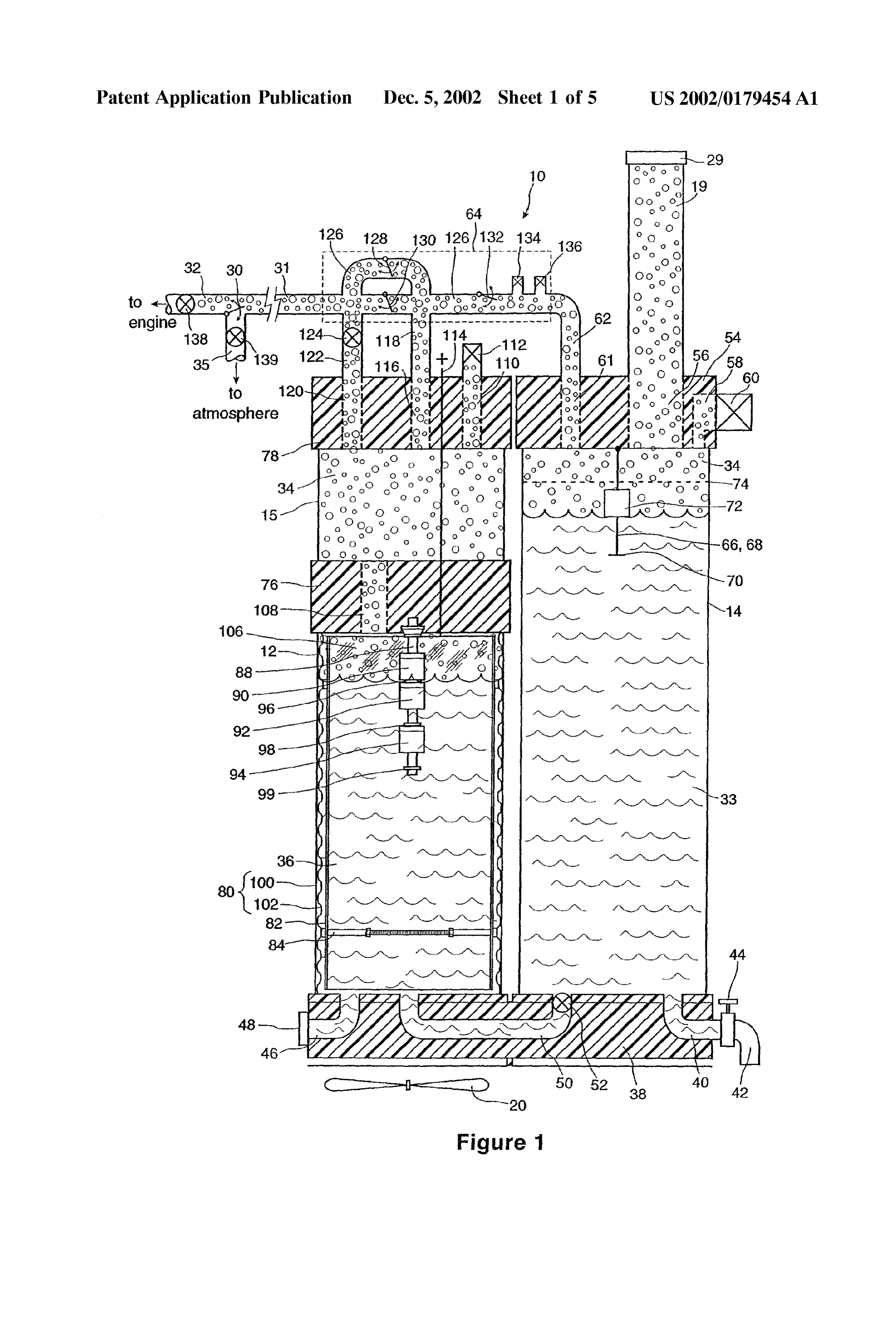
US 2002/0179454 A1 Dec. 5, 2002
ELECTROLYSIS CELLAND INTERNAL the working fluid, water, and hydrogen. Implementing Such COMBUSTION ENGINE KIT COMPRISING THE a complicated System would be costly, require extensive SAME effort to integrate with existing engines, and likely involve Significant maintenance due to the many additional compo
FIELD OF THE INVENTION nents. Further, Bradley does not even address the risk of an 0001. This invention relates to the general field of com explosion, particularly from the hydrogen tank, or provide bustion engines, and more particularly to an electrolysis cell any means to keep the System running in cold weather, when for Supplying gaseous fuel additives to enhance combustion the water that supplies the electrolysis cell would be frozen. in a combustion engine. 0006 U.S. Pat. No. 5,231,954 to Stowe attempts to provide a simpler electrolysis System for generating hydro
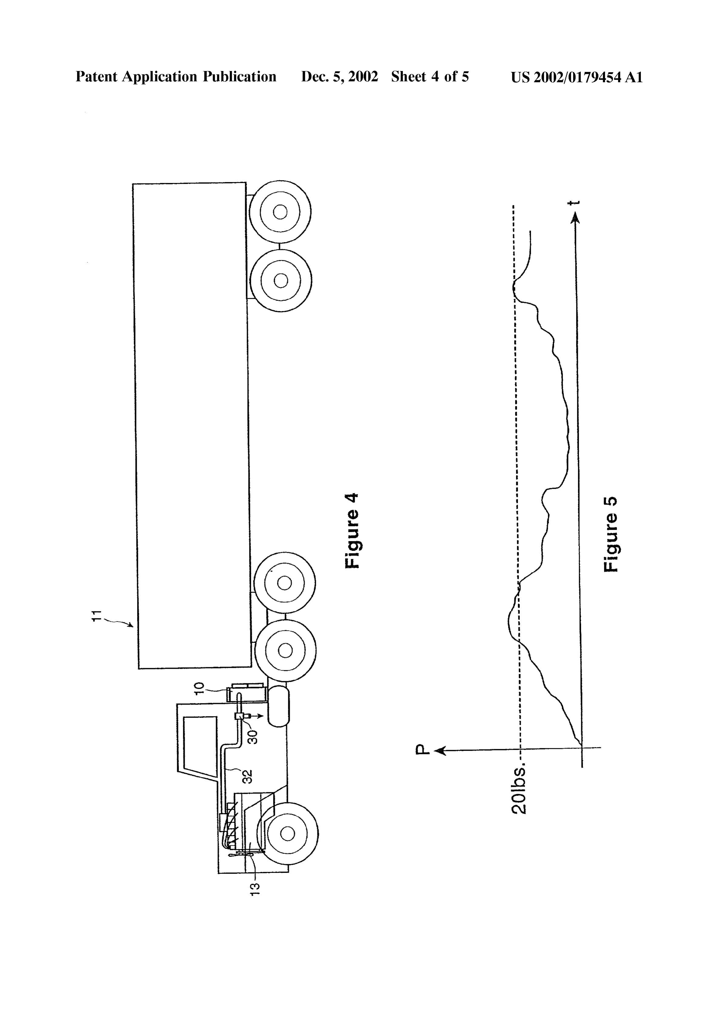
BACKGROUND OF THE INVENTION gen and oxygen gases on board a vehicle. The device is a Single electrolysis chamber or cell that receives power 0002 Modern gasoline and diesel engines are more effi directly from the vehicle battery, and has a gas-out line that cient and leSS polluting than Similar engines of even a few connects with the positive crankcase ventilation (PCV) years ago. However, due to the increased total number of System of the engine. When the engine is running a vacuum vehicles in use, levels of air pollution continue to rise even is created in the PCV line which is used to draw the gases in light of more efficient and clean running vehicles. There out of the cell and into the engine. There is also an air intake fore, there has been increasing pressure to develop vehicles adjustment valve that is always open to the atmosphere. This which have lower emissions, and thus are leSS polluting than Valve is adjusted to mix air with the generated gases So as to conventional automotive technology permits. This has meet emission control regulations. The operator adds elec Spurred development of alternate fuel technologies Such as trolyte concentrate to water in the cell until a reading of electric cars and Vans, natural gas and propane fuelled 1.5-3.0 amperes is obtained. Thereafter, water is to be added vehicles, hydrogen cell vehicles and the like. While a manually to the cell about every 1000 miles. The cell has a number of these technologies are promising, Some are still friction-fit cap that secures tightly when exposed to the PCV a long way from commercial implementation, and others line vacuum, and that loosens when the engine and associ appear to have reached the limit of present design capabili ated vacuum is turned off. The loose cap is intended to pop ties without yielding a consumer acceptable product. There off to provide relief from high pressure build-up in the cell fore, attention has refocused on conventional gas and diesel when the engine is turned off.
burning engines, and ways to render them more pollution free and efficient. 0007 Since the Stowe device receives power directly from the battery, the current level is set by adjusting the 0003. It is well known that the addition of hydrogen and electrolyte concentration. The result is a high resistance, low oxygen gases as fuel increases the efficiency of an internal current cell that generates excessive heat, which is problem combustion engine and reduces pollution considerably. Both atic. The heat problem is exacerbated by the plastic walls advantages appear to be the byproduct of faster flame Speed used in the preferred embodiment, Since plastic does not that is as much as nine times that of gasoline, resulting in conduct heat well, and by the fact that no cooling mecha more complete combustion of the fuel in the combustion nism is taught.
chamber. The amount of soot (semi-burnt hydrocarbons), 0008 Further, while the device proposed aims to be nitrous oxide, carbon monoxide, and other pollutants is Simple to install and use, pre-mixing and pre-charging of the accordingly reduced, while output energy increases, for a electrolyte is awkward, particularly for consumer use. greater fuel efficiency and horsepower. Another complicating feature is that the air intake valve 0004 One way to adopt hydrogen and oxygen as a fuel requires adjustment by emission control mechanics. Further, additive is to Store the gases in tanks installed on a vehicle, Since this valve is always open to the atmosphere, it will with hoses connecting the tanks to the engine. However, likely draw dirty air into the cell. Stowe also teaches that this tank Storage of these volatile gases presents a persistent Valve has a dual purpose in that it acts as a Safety release Safety hazard, Since there is always a risk of gas leak and valve if cell pressure rises. However it is not clear how an explosion. It also requires regular trips to a Service Station opening sized to meet emission requirements (likely a small for replenishment, which is inconvenient. Further, the pre opening) will also function effectively in a totally different vailing service station network would need to be retrofitted context as a Safety release. Therefore the Stowe device may at great cost to Supply these gases, which would also require lack Sufficient Safety release features to reduce the risk of widespread coordination of Standards that could unduly explosion when there is a rise in pressure. delay acceptance of the technology. As a result of these 0009. Yet another issue is that the PCV vacuum line problems with tank Storage, various attempts have been required to operate the device is available with gasoline, but made to develop Systems in which the gases could be not diesel, internal combustion engines. Further, water generated on board the vehicle itself, using well-known replenishment is estimated at about every 1000 miles of technologies Such as electrolysis, for use by the engine as driving. While this may be adequate for consumer use, it needed. would require inconveniently frequent replenishment by 0005. An example of such a system is taught in U.S. Pat. commercial vehicle drivers who may drive that distance No. 3,939,806 to Bradley. This system is quite complicated every few days. Therefore, the Stowe device would not be however Since it includes a mechanism to generate DC Suitable for use by most commercial vehicles, particulary the current to power the electrolysis cell. This requires a work large diesel trucks which produce a high proportion of ing fluid Such as water or freon and accompanying circula pollution.
tion System, a turbine and DC generator, a hydrogen carbu 0010 Another electrolysis device is shown in U.S. Pat. retor and hydrogen Storage tank, and Several pumps to move No. 4,271,793 to Valdespino. This patent teaches that the
Page 8
US 2002/0179454 A1 Dec. 5, 2002
battery associated with most vehicle engines does not pro and undermine acceptance of an otherwise highly desirable vide enough current to produce meaningful amounts of technology. Accordingly, it is important that the device be hydrogen and oxygen gases, and accordingly requires that a designed to minimize this risk as much as possible. The larger or Second alternator be installed. However, this device therefore should preferably include venting features arrangement increases the amount of heat generated, which to relieve gas pressure before it has a chance to build up to in turn requires installation of a separate water jacket Sup dangerous levels. Further, it would be especially advanta plied by the vehicle cooling System. These additional com geous if in the unlikely event of the venting features failing ponents add cost and complicate integration of the device or of a Spark being introduced, the Structure of the device with conventional engines. itself could contain the ensuing explosion, So that the risk of 0.011 The high level of generated heat presents a risk of harm to the vehicle occupants would be measurably reduced.
boil-off of the electrolyte. To deal with this issue Valdespino places a valve in the output gas line to maintain a high cell 0017. The electrolysis cell of the present invention uses internal pressure. The preferred pressure range is 50-150 psi, electrodes constructed of expanded nickel to generate gas, typically 100 psi. However, maintaining Such high internal and includes a region designated as an electrolytic fog. A fan preSSure generally increases the risk of an explosion and and condenser help lower the temperature of the gas and makes routine re-fill of the electrolyte a more complicated reduce moisture. The electrolysis is further enhanced by and risky procedure. It also compels the cell walls to be regulating the power input to the cell. In this way the device thicker than otherwise, adding to the weight of the cell. The of the present invention produces an adequate Supply of gas gas output from the cell passes through an accumulator and to aid combustion. The device delivers the gas to the engine from there is delivered to the intake manifold of the engine under pressure, thereby ensuring a constant flow even when under a vacuum. the air intake pressure is high due to turbocharger boost. The gases are continuously available, aided by a separate on 0012 Unless these and other practical problems associ board water Supply that automatically replenishes the cell ated with this technology are resolved, the improved effi when needed. The device contains both heating and cooling ciency and reduced pollution benefits possible from using features that enable gas to be generated in extreme weather hydrogen and oxygen as a fuel additive will fail to be conditions. The only operator maintenance required is to realized.
occasionally refill the water Supply. Even under commercial
SUMMARY OF THE INVENTION
driving conditions, only one refill approximately every 3-4 weeks should be sufficient. The cell and kit are made of 0013 What is required is an electrolysis cell and internal Sturdy and simple components, with no moving parts or combustion engine kit which overcomes the problems asso complicated electronics, So that breakdowns are infrequent ciated with the current devices used to generate hydrogen and Service costs minimized. Further, the device readily and oxygen gases as a fuel additive for combustion engines. connects with existing engines. Power is received from the vehicle battery, and the output gas hose Simply attaches to a 0.014) Most particularly, the device should produce Standard input at the air intake manifold. The device hydrogen and oxygen gas in Sufficient quantity to improve includes overlapping Safety venting features to relieve inter the combustion efficiency of the internal combustion engine nal gas pressure if the preSSure rises above Standard oper to which it is connected. The device should deliver the ating levels. Further, the device is built to pressure vessel generated gases effectively and consistently to the engine, So Standards So that in the unlikely event that an explosion that the benefits of the gases as a fuel additive are realized. occurs, it will be contained and less likely to cause actual Preferably, the device will work with different types of harm.
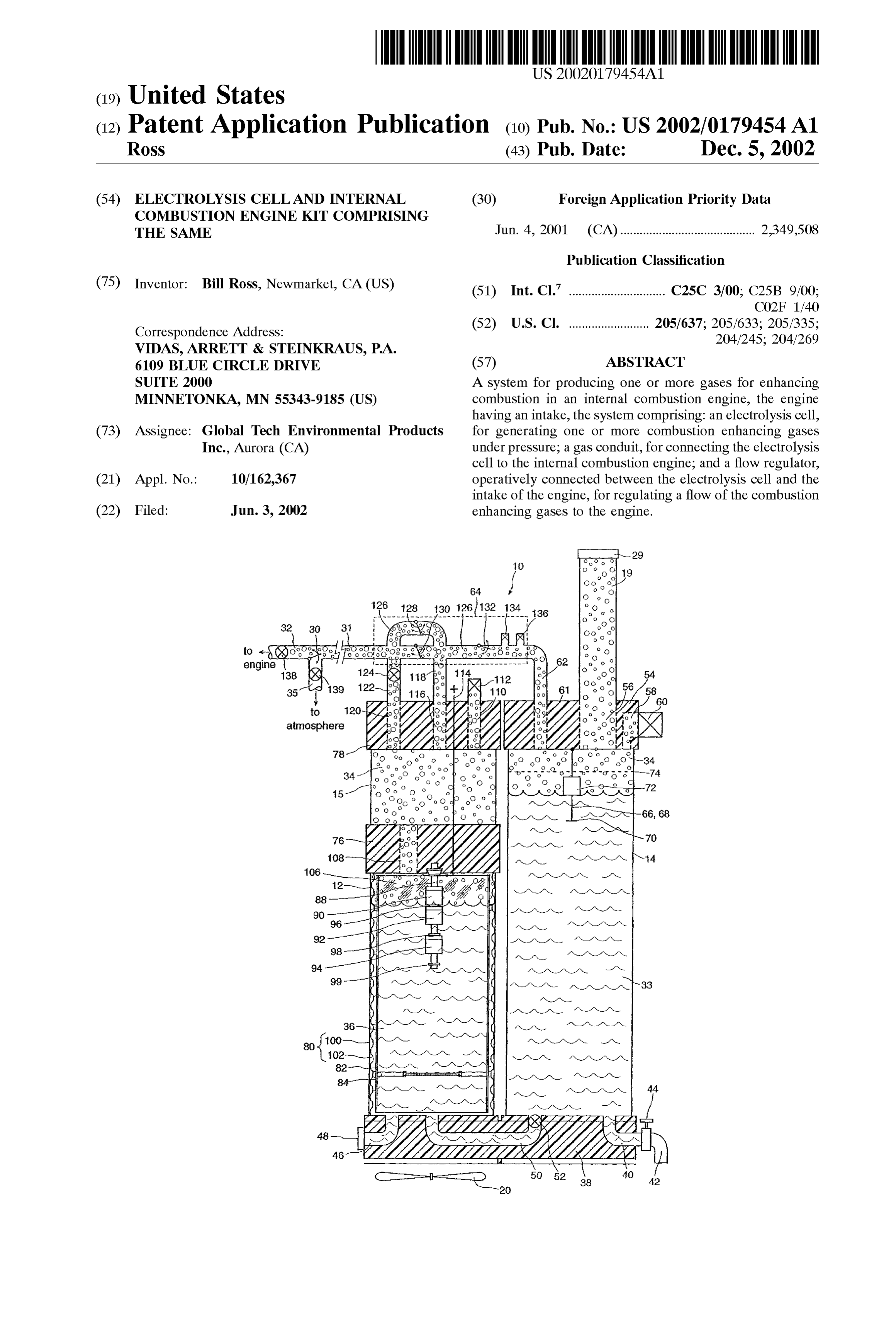
engines, and particularly with turbocharged diesel engines 0018. Accordingly, there is provided a system for pro typically used by commercial trucks that are heavy users of ducing one or more gases for enhancing combustion in an fuel. It would be advantageous if it could provide the gas internal combustion engine, Said engine having an intake, throughout the duration of a trip without disruption, and in the System comprising:
any weather condition which the vehicle may be expected to encounter, including both freezing winter and hot Summer 0019 an electrolysis cell, for generating one or more temperatures. combustion enhancing gases under pressure; 0.015 The device should be simple to operate, requiring 0020 a gas conduit, for connecting the electrolysis minimal operator attention and maintenance. Preferably, the cell to the internal combustion engine; and device should require little more than an occasional water 0021 a flow regulator, operatively connected refill. It would also be advantageous for the device to be constructed from components that are relatively simple and between the electrolysis cell and the intake of the durable, So that breakdowns will be infrequent and Servicing engine, for regulating a flow of Said combustion Straightforward to perform. Yet another advantage would be enhancing gases to Said engine. for the device to be easy to install in a vehicle, without BRIEF DESCRIPTION OF THE DRAWINGS requiring extensive engine modification.
0016. In any gas apparatus there is inevitably a risk of 0022 Reference will now be made, by way of example blockages developing in the gas circulation System, leading only, to preferred embodiments of the invention as illus to a rise in preSSure and an explosion. Since the device of the trated in the attached figures.
present invention is used in motor vehicles that contain 0023 FIG. 1 is a front, cut-away view of the electrolysis highly flammable hydrocarbon fuel and one or more people cell and internal combustion engine kit of the present in close proximity, a gas explosion could cause Serious harm invention;
Page 9
US 2002/0179454 A1 Dec. 5, 2002
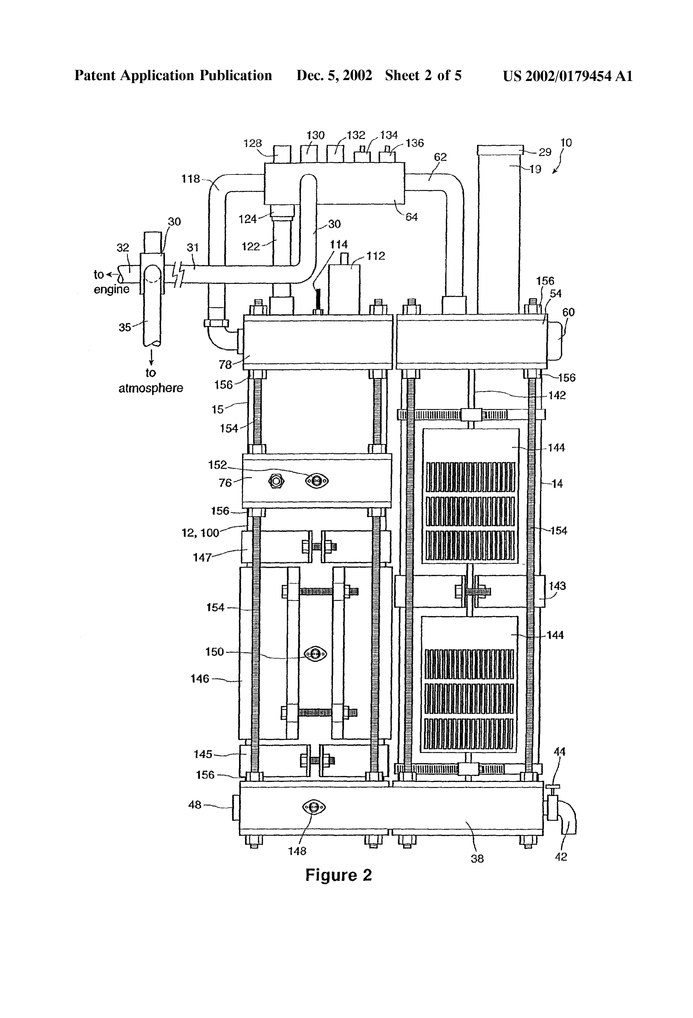
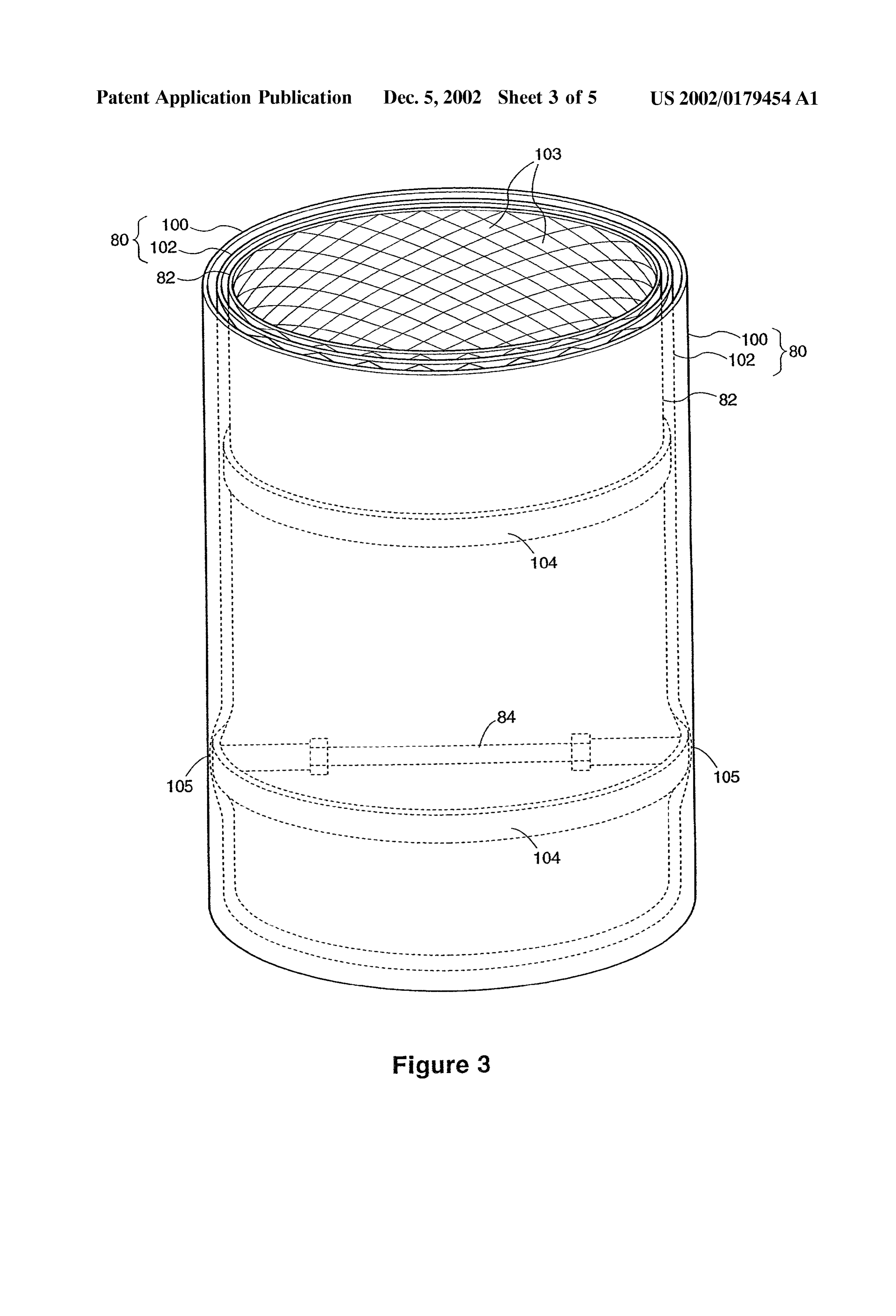
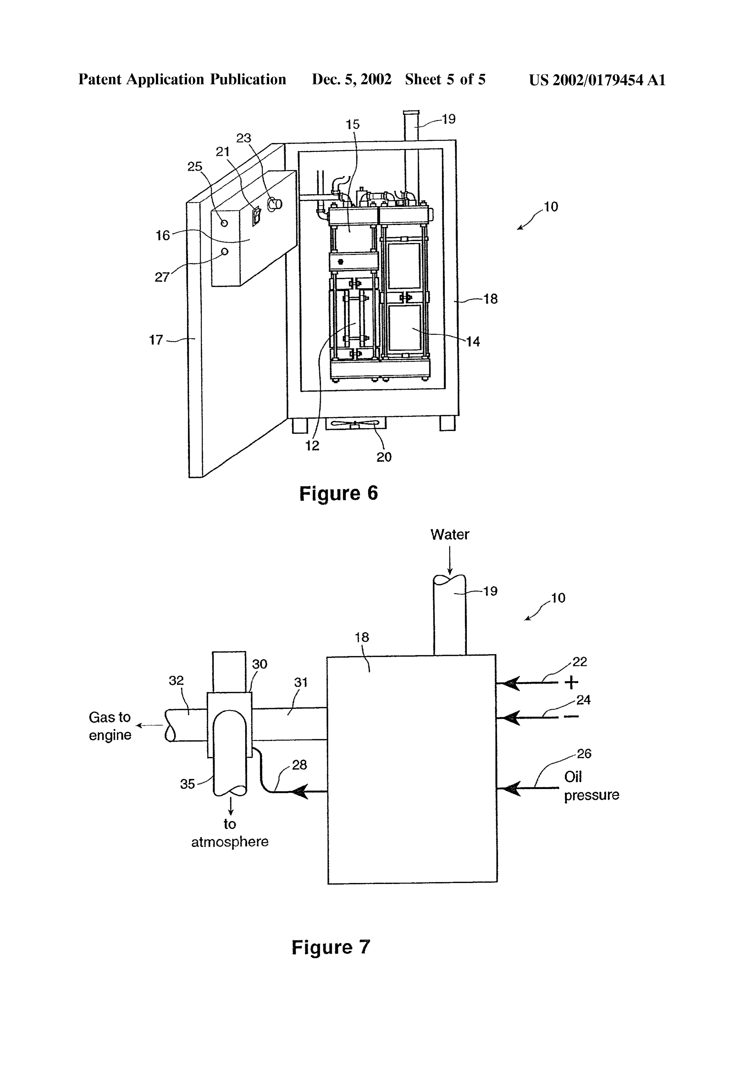
0024 FIG. 2 is a front view of the electrolysis cell and colored green and red respectively, though it can be appre internal combustion engine kit of FIG. 1; ciated that other colors may also be used. 0025 FIG.3 is a perspective view of the electrolysis cell 0033. The case 18 is preferably constructed from sheet of FIGS. 1 and 2, showing hidden features; metal, but it can be appreciated that any material that is light, Strong, and preferably inexpensive may be adequate. For a 0.026 FIG. 4 is a diagram view of the internal combus large tractor-trailer truck or Similar vehicle it has been found tion engine kit of the present invention mounted on a that the invention may be housed in a case 18 that is about vehicle; 12 inches wide by about 24 inches high and 12 inches deep. 0.027 FIG. 5 is a representative graph of air intake A case of this size may be conveniently mounted outside the preSSure of an internal combustion engine against time; vehicle, Such as on the Side, beside the fuel tank. It can be appreciated that for this type of vehicle the case 18 should 0028 FIG. 6 is a front perspective view of the electroly be Sufficiently Sturdy and well-sealed to provide adequate sis cell and internal combustion engine kit of the present protection from the elements. It can Similarly be appreciated invention, including the case enclosure, and that when applied to Smaller vehicles Such as passenger cars or light trucks, the invention may be housed in a case 18 that 0029 FIG. 7 is a diagram view of the external connec has Smaller dimensions and that may be mounted Some tions of the internal combustion engine kit of the present where inside the vehicle Such as in the trunk or engine invention. compartment.
DETAILED DESCRIPTION OF THE 0034 FIG. 7 is a diagram view of the present invention PREFERRED EMBODIMENTS 10 showing the external connections into and out of the case 18. There is a positive lead 22 and a negative lead 24 that 0030 The present invention is for a system comprising an directly connect electrically with the respective positive and electrolysis cell and asSociated kit that generates and deliv negative terminals of the vehicle battery (not shown). Simi ers a gas that acts as a fuel additive for an internal combus larly, an oil preSSure lead 26 is directly connected to the oil tion engine. Electrolysis is a well known proceSS whereby an preSSure Switch provided as a Standard feature of internal electrical current is passed through a water-based Solution. combustion engines. Solenoid lead 28 is an electrical output The current splits the water molecules, releasing hydrogen line that activates an external Solenoid 30, which is mounted and oxygen gases which can be directed to the engine. The external to the case 18. The various electrical inputs 22, 24, gases are injected into the engine at the air intake, where and 26, and the electrical output 28 connect to the electrical they enhance combustion of the hydrocarbon fuel used by box 16 inside case 18. The other external connections of the the engine. device 10 include the water input pipe 19 and a gas conduit or gas output hose 31, which connects the cell 12 to the 0031. The invention finds particular application with external Solenoid 30. Another gas conduit or gas output hose motor vehicles that are powered by internal combustion 32 further connects external Solenoid 30 with the engine. engines. The invention may be used with a variety of Gas output hoses 31 and 32 together represent a gas conduit vehicles and fuels, including conventional passenger cars that carries combustion enhancing gas from the cell 12 to an having gasoline engines, commercial trucks that use diesel internal combustion engine. Another gas output hose 35 engines and turbochargers, as well as Specialized vehicles vents external Solenoid 30 to atmosphere. such as forklifts or tractors that may be powered by less common fuels. Such as propane, methane, or natural gas. The 0035 FIG. 4 shows the invention 10 mounted on the preferred embodiment described herein has been configured outside of a tractor-trailer type vehicle 11 having an internal to meet the particular needs of large vehicles, Such as the combustion engine 13. It can be seen that external Solenoid turbocharged, diesel engine powered commercial tractor 30 may be conveniently mounted on the frame of the vehicle trailer trucks commonly used to move goods over long 11. The engine 13 has an intake or air intake manifold which distances. It will be appreciated by those skilled in the art receives air for use in the combustion process. Gas output that the principles of the invention may be applied to other hose 32 may be conveniently attached to the air intake types of vehicles and internal combustion engines without manifold of the engine 13 at a Standard plug input precast to departing from the Spirit of the present invention. receive auxiliary hoses.
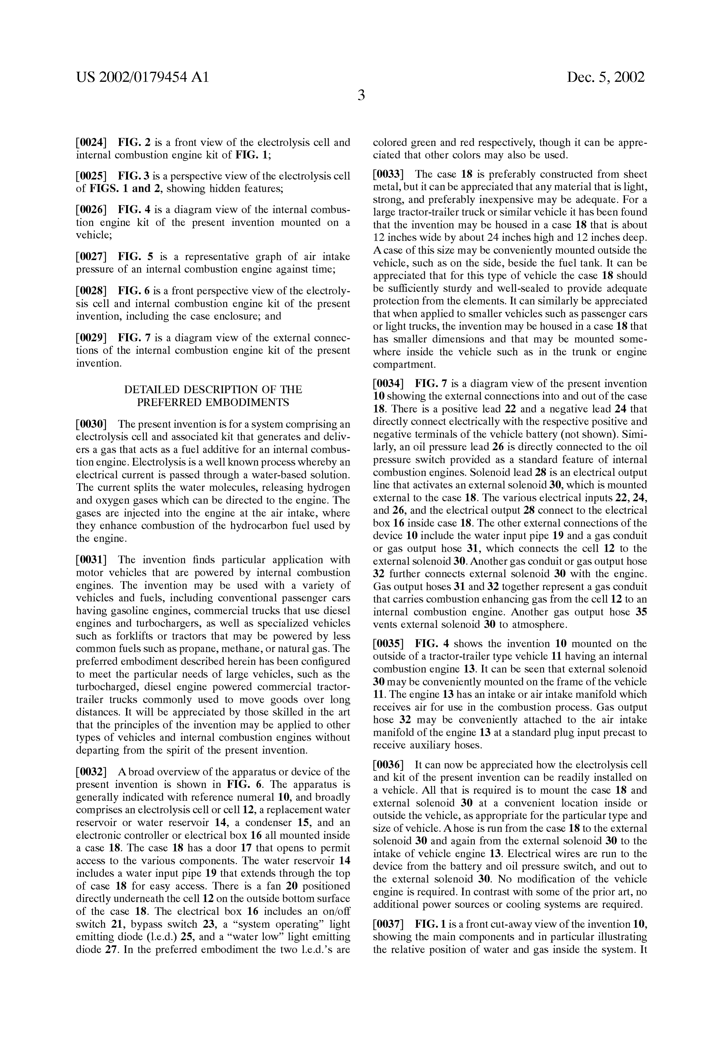
0032. Abroad overview of the apparatus or device of the 0036. It can now be appreciated how the electrolysis cell present invention is shown in FIG. 6. The apparatus is and kit of the present invention can be readily installed on generally indicated with reference numeral 10, and broadly a vehicle. All that is required is to mount the case 18 and external Solenoid 30 at a convenient location inside or comprises an electrolysis cell or cell 12, a replacement water outside the vehicle, as appropriate for the particular type and reservoir or water reservoir 14, a condenser 15, and an size of vehicle. Ahose is run from the case 18 to the external electronic controller or electrical box 16 all mounted inside a case 18. The case 18 has a door 17 that opens to permit Solenoid 30 and again from the external Solenoid 30 to the access to the various components. The water reservoir 14 intake of vehicle engine 13. Electrical wires are run to the includes a water input pipe 19 that extends through the top device from the battery and oil pressure Switch, and out to the external Solenoid 30. No modification of the vehicle of case 18 for easy access. There is a fan 20 positioned engine is required. In contrast with Some of the prior art, no directly underneath the cell 12 on the outside bottom surface additional power Sources or cooling Systems are required. of the case 18. The electrical box 16 includes an on/off
Switch 21, bypass Switch 23, a “system operating light 0037 FIG. 1 is a front cut-away view of the invention 10, emitting diode (1.e.d.) 25, and a “water low light emitting showing the main components and in particular illustrating diode 27. In the preferred embodiment the two 1.e.d.’s are the relative position of water and gas inside the System. It
Page 10
US 2002/0179454 A1 Dec. 5, 2002
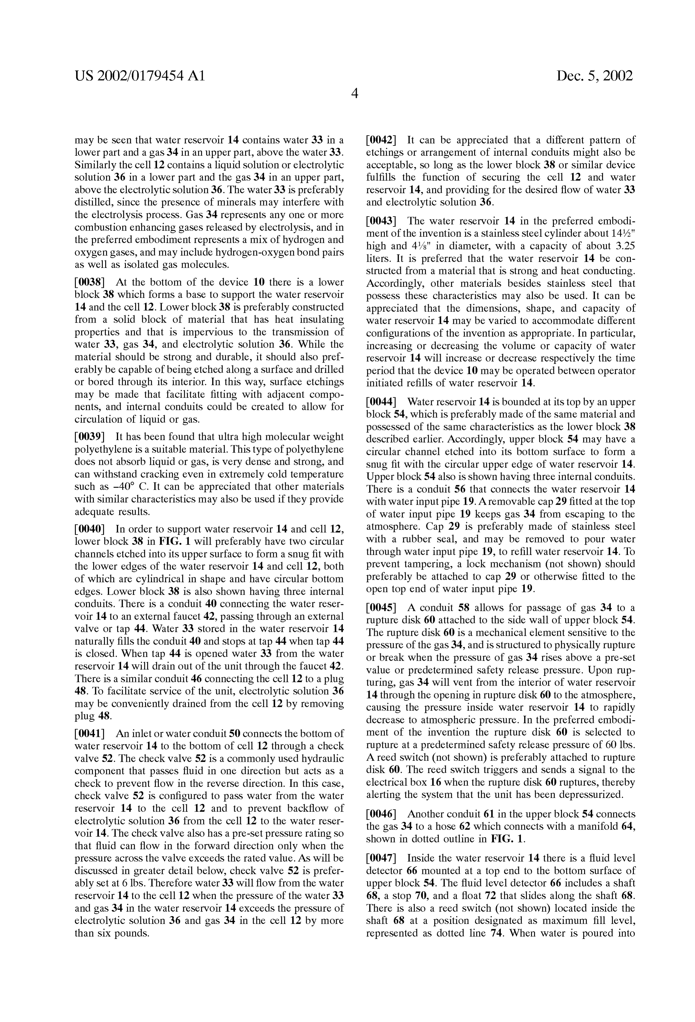
may be seen that water reservoir 14 contains water 33 in a 0042. It can be appreciated that a different pattern of lower part and a gas 34 in an upper part, above the water 33. etchings or arrangement of internal conduits might also be Similarly the cell 12 contains a liquid solution or electrolytic acceptable, so long as the lower block 38 or similar device Solution 36 in a lower part and the gas 34 in an upper part, fulfills the function of securing the cell 12 and water above the electrolytic solution 36. The water 33 is preferably reservoir 14, and providing for the desired flow of water 33 distilled, Since the presence of minerals may interfere with and electrolytic solution 36.
the electrolysis process. Gas 34 represents any one or more 0043. The water reservoir 14 in the preferred embodi combustion enhancing gases released by electrolysis, and in ment of the invention is a stainless steel cylinder about 14%." the preferred embodiment represents a mix of hydrogen and high and 4/s" in diameter, with a capacity of about 3.25 oxygen gases, and may include hydrogen-oxygenbond pairs as well as isolated gas molecules. liters. It is preferred that the water reservoir 14 be con Structed from a material that is Strong and heat conducting.
0038. At the bottom of the device 10 there is a lower Accordingly, other materials besides Stainless Steel that block 38 which forms a base to support the water reservoir possess these characteristics may also be used. It can be 14 and the cell 12. Lower block 38 is preferably constructed appreciated that the dimensions, shape, and capacity of from a Solid block of material that has heat insulating water reservoir 14 may be varied to accommodate different properties and that is impervious to the transmission of configurations of the invention as appropriate. In particular, water 33, gas 34, and electrolytic solution 36. While the increasing or decreasing the Volume or capacity of water material should be strong and durable, it should also pref reservoir 14 will increase or decrease respectively the time erably be capable of being etched along a Surface and drilled period that the device 10 may be operated between operator or bored through its interior. In this way, Surface etchings initiated refills of water reservoir 14. may be made that facilitate fitting with adjacent compo nents, and internal conduits could be created to allow for 0044) Water reservoir 14 is bounded at its top by an upper circulation of liquid or gas. block 54, which is preferably made of the same material and possessed of the same characteristics as the lower block 38 0039. It has been found that ultra high molecular weight described earlier. Accordingly, upper block 54 may have a polyethylene is a Suitable material. This type of polyethylene circular channel etched into its bottom Surface to form a does not absorb liquid or gas, is very dense and Strong, and Snug fit with the circular upper edge of water reservoir 14. can withstand cracking even in extremely cold temperature Upper block 54 also is shown having three internal conduits. Such as -40 C. It can be appreciated that other materials There is a conduit 56 that connects the water reservoir 14 with Similar characteristics may also be used if they provide with water input pipe 19. A removable cap 29 fitted at the top adequate results. of water input pipe 19 keeps gas 34 from escaping to the 0040. In order to support water reservoir 14 and cell 12, atmosphere. Cap 29 is preferably made of stainless steel lower block 38 in FIG. 1 will preferably have two circular with a rubber Seal, and may be removed to pour water channels etched into its upper Surface to form a Snug fit with through water input pipe 19, to refill water reservoir 14. To the lower edges of the water reservoir 14 and cell 12, both prevent tampering, a lock mechanism (not shown) should of which are cylindrical in shape and have circular bottom preferably be attached to cap 29 or otherwise fitted to the edges. Lower block 38 is also shown having three internal open top end of water input pipe 19. conduits. There is a conduit 40 connecting the water reser 0045. A conduit 58 allows for passage of gas 34 to a voir 14 to an external faucet 42, passing through an external rupture disk 60 attached to the side wall of upper block 54. valve or tap 44. Water 33 stored in the water reservoir 14 The rupture disk 60 is a mechanical element sensitive to the naturally fills the conduit 40 and stops at tap 44 when tap 44 preSSure of the gas 34, and is structured to physically rupture is closed. When tap 44 is opened water 33 from the water or break when the pressure of gas 34 rises above a pre-Set reservoir 14 will drain out of the unit through the faucet 42. value or predetermined Safety release pressure. Upon rup There is a Similar conduit 46 connecting the cell 12 to a plug turing, gas 34 will vent from the interior of water reservoir 48. To facilitate service of the unit, electrolytic solution 36 14 through the opening in rupture disk 60 to the atmosphere, may be conveniently drained from the cell 12 by removing causing the pressure inside water reservoir 14 to rapidly plug 48. decrease to atmospheric pressure. In the preferred embodi 0041 An inlet or water conduit 50 connects the bottom of ment of the invention the rupture disk 60 is selected to water reservoir 14 to the bottom of cell 12 through a check rupture at a predetermined Safety release pressure of 60 lbs. valve 52. The check valve 52 is a commonly used hydraulic A reed Switch (not shown) is preferably attached to rupture component that passes fluid in one direction but acts as a disk 60. The reed Switch triggers and Sends a Signal to the check to prevent flow in the reverse direction. In this case, electrical box 16 when the rupture disk 60 ruptures, thereby check valve 52 is configured to pass water from the water alerting the System that the unit has been depressurized. reservoir 14 to the cell 12 and to prevent backflow of 0046) Another conduit 61 in the upper block 54 connects electrolytic solution 36 from the cell 12 to the water reser the gas 34 to a hose 62 which connects with a manifold 64, voir 14. The check valve also has a pre-Set pressure rating So shown in dotted outline in FIG. 1. that fluid can flow in the forward direction only when the preSSure acroSS the valve exceeds the rated value. AS will be 0047 Inside the water reservoir 14 there is a fluid level discussed in greater detail below, check valve 52 is prefer detector 66 mounted at a top end to the bottom surface of ably set at 6 lbs. Therefore water 33 will flow from the water upper block 54. The fluid level detector 66 includes a shaft reservoir 14 to the cell 12 when the pressure of the water 33 68, a stop 70, and a float 72 that slides along the shaft 68. and gas 34 in the water reservoir 14 exceeds the pressure of There is also a reed switch (not shown) located inside the electrolytic solution 36 and gas 34 in the cell 12 by more shaft 68 at a position designated as maximum fill level, than six pounds. represented as dotted line 74. When water is poured into
Page 11
US 2002/0179454 A1 Dec. 5, 2002
water input pipe 19 the level of water 33 will rise above the Solution 36 not include any anti-foaming agents, Since this stop 70 and cause float 72 to rise from its rest position at the Substance could migrate to the electrodes and interfere with stop 70. When float 72 further rises to the maximum fill level electrolysis.
74, float 72 will engage the reed Switch, causing a signal to be sent that activates a buzzer (not shown) that alerts the 0052 Once the electrolytic solution 36 is mixed the water operator to Stop filling the water reservoir 14. The maximum component requires regular replenishment but the KOH fill level 74 is purposely set some distance below the upper generally only needs replenishment after about 3 years of block 54 So that there will be room to accommodate the normal use. It is preferred that the electrolytic solution 36 be expansion of water 33 if it freezes and becomes ice, which initially Supplied with the kit of the present invention, and will occur if the unit is left turned off for an extended period that the KOH component thereafter be replenished only by of time in freezing temperature. In the preferred embodi qualified Service perSonnel. It is preferred that access to ment, this distance is approximately 1.5 inches from the top. KOH be restricted to qualified service personnel because KOH is a caustic material that can cause accidental harm if
It can be appreciated that other means besides a fluid level detector may also be used, as long as it functions to alert the mishandled by individuals not familiar with its use, and operator to Stop refilling the water reservoir 14 at the because accurate apportion of the KOH is important to maximum fill level 74. obtain efficient electrolysis. AS will be discussed in greater detail, the water component of electrolytic solution 36 is 0.048 Turning now to the electrolysis cell 12, there is replenished regularly and automatically from the water above the cell 12 a separator block 76, the condenser 15, and reservoir 14.
an upper block 78. Overall, the height from the base of cell 12 to the top of condenser 15 is about 14%", approximately 0053 FIG.3 shows the cathode 80 and anode 82 in more detail. From this view it can be seen that the cathode 80 the same height as water reservoir 14. Cell 12 and condenser comprises two parts, an outer shell 100 and an inner mesh 15 are both cylinders having a diameter about 4/4", approxi mately the same as the diameter of the water reservoir 14. 102. As may be seen from the figure, outer shell 100, inner The height of cell 12 alone is preferably between 8 and 12 mesh 102, and the anode 82 are all cylindrical in shape, have inches, and in the preferred embodiment is 10 inches. It can the same or approximately the same height, and are of be appreciated that these dimensions may vary to accom approximately the same width. The height of each electrode modate different configurations of the invention as appro is about 10 inches. The outer shell 100 is about 4/4 inches priate. in diameter with the inner mesh 102 and anode 82 each being progressively slightly Smaller in diameter So as to fit 0049 Electrolysis cell 12 contains two electrodes instru within outer shell 100. The anode 82 is physically spaced mental to the electrolysis process, a cathode electrode or apart and electrically insulated from the cathode 80, or more cathode 80, and an anode electrode or anode 82. Also shown particularly, from the inner mesh 102, by spacers 104 shown is a tensioner 84. As will be shown in more detail below, in dotted line in FIG. 3. In the preferred embodiment the tensioner 84 is used to maintain an electrical connection spacers 104 comprise two rings that encircle the anode 82 between two parts of the cathode 80. and are each approximately /16 inch thick. The Spacers 104 keep the anode 82 and cathode 80 safely apart, but close 0050. Inside cell 12 there is a float sensor or fluid level enough to permit electrolysis to proceed productively. The detector 88 to detect the level of electrolytic solution 36 in preferred material for the Spacers 104 is plastic, Since plastic cell 12. This element is fixed in place through its connection is electrically insulating, durable, and resistant to degrada at a top end to the bottom surface of separator block 76. tion by KOH, but it can be appreciated that other materials Fluid level detector 88 has three floats-a top or safety float with Similar characteristics would also be acceptable. AS 90, a middle or fill float 92, and a re-fill or low float 94. well, the spacers 104 may be formed using a different There is a stop 96 between the safety float 90 and fill float number of rings or have a different Structure than a ring as 92, a stop 98 between the fill float 92 and the low float 94, long as the function of keeping the cathode 80 and anode 82 and a stop 99 at the bottom of the shaft of level detector 88. safely apart is fulfilled.
Each float is slidable along a portion of the shaft of level detector 88 defined by the closest higher and lower stops. 0054 By virtue of their similar diameters, the outer There are also four reed switches (not shown) embedded in cylindrical surface of inner mesh 102 essentially makes the shaft of fluid level detector 88: a first reed Switch located contact all along its Surface with the inner cylindrical Surface near the top of the shaft at a predetermined high point that of outer shell 100, in effect forming cathode 80 as a single is activated by safety float 90, a second reed Switch located physical unit. To further ensure electrical contact, tensioner under stop 96 at a predetermined fill point that is activated 84 is placed inside the anode 82 just behind one of the by fill float 92, and a third reed switch located under stop 98 spacers 104. In that position tensioner 84 exerts an outward at a predetermined re-fill point and a fourth reed Switch preSSure against the anode 82 and Spacer 104, causing Spacer located closer to stop 99 at a predetermined low point, both 104 to firmly press inner mesh 102 into outer shell 100 at of which are activated by the re-fill or low float 94. two points of contact 105. Tensioner 84 is preferably a threaded nickel rod with nylon bushings at each end. The 0051) The body or cylinder of cell 12 defines an interior bushings may be threaded along the rod to reach an appro Space that primarily contains electrolytic Solution 36, above priate position for maintaining the desired outward pressure. which there is gas 34. The liquid solution or electrolytic
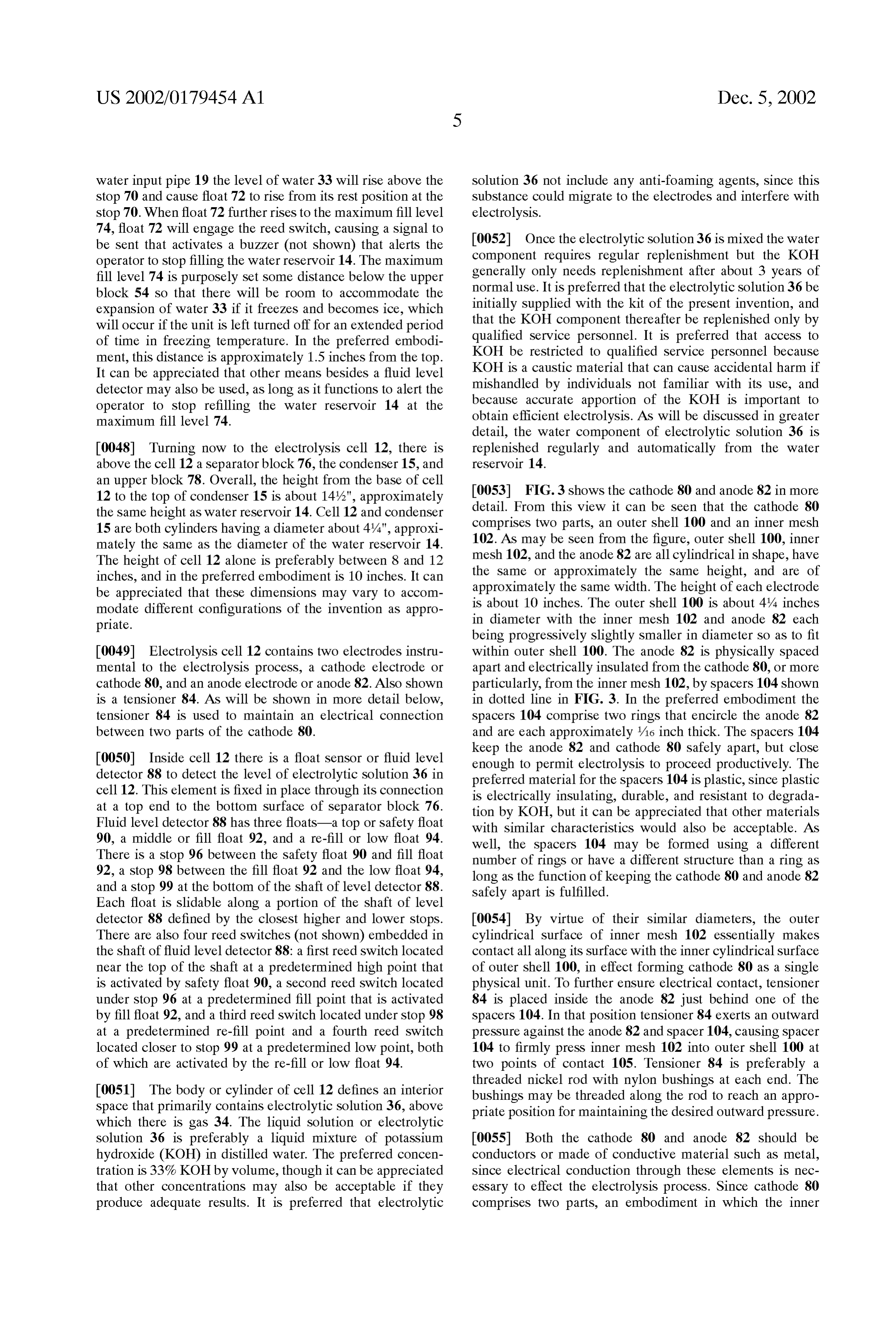
Solution 36 is preferably a liquid mixture of potassium 0055. Both the cathode 80 and anode 82 should be hydroxide (KOH) in distilled water. The preferred concen conductors or made of conductive material Such as metal, tration is 33% KOH by volume, though it can be appreciated Since electrical conduction through these elements is nec that other concentrations may also be acceptable if they essary to effect the electrolysis process. Since cathode 80 produce adequate results. It is preferred that electrolytic comprises two parts, an embodiment in which the inner
Page 12
US 2002/0179454 A1 Dec. 5, 2002
mesh 102 is a conductor and outer shell 100 is not may also 0059. It can also be appreciated that the positions of the be acceptable. Preferably the electrodes are made from a cathode 80 and anode 82 could be reversed, with the anode pure form of a noble metal Such as nickel, platinum, palla 82 becoming the outer electrode having an outer shell 100 dium, rhodium, or titanium. Noble metals have the benefit of and inner mesh 102, and the cathode 80 becoming the inner not reacting with KOH, and the facility to enhance elec electrode, without any effect on the efficiency of the cell 12. trolysis by lending electrons to enhance current flow through In practical terms this can be accomplished merely by electrolytic solution 36. A pure noble metal rather than an Switching the electrical inputs to the electrode terminals. amalgam with a non-noble metal is desirable because a Similarly, different electrode architectures other than two non-noble metal may react with KOH and plate or corrode cylinders in close engagement could also be employed if the electrodes. In the preferred embodiment of the invention they give adequate results.
nickel having a purity level designated as "nickel 200” has 0060 Returning to FIG. 1, it can be seen that the cathode been found to provide adequate results. An advantage of 80 and anode 82 extend the full height of the cell 12, which nickel is that it possesses a cubic-faced center molecular is 10 inches in the preferred embodiment. It can be appre Structure which has many reflective edges. It is well known ciated that the electrodes may be made less than the full that gas production from electrolysis is enhanced in propor height of the cell 12 if desired. The electrolytic solution 36 tion to the number of edges on the electrodes. Other benefits fills a lower part of the cell 12 to a level less than the height of nickel are that it is inherently Strong, So that the cathode of the electrodes, and the gas 34 occupies an upper part or and anode can be made rigid and durable, and that it is space above the electrolytic solution 36. That part of the cell generally lower in cost than Some of the other noble metals. 12 occupied by the gas 34 and that is above the electrolytic It can be appreciated that other noble metals or other metals Solution 36 is designated as a gas Space for an electrolytic that generate acceptable amounts of hydrogen would also be fog 106. In the preferred embodiment the level of the adequate. electrolytic Solution 36 is about 8 inches and the gas Space 0056. In the preferred embodiment the outer shell 100 is 106 is therefore about 2 inches high. As will be seen, during comprised of Schedule 10 Seamless nickel pipe. By contrast operation of the cell 12 these levels may change to about 6 at least one, and preferably both of the inner mesh 102 and inches and 4 inches respectively, as the level of electrolytic anode 82 are constructed from an expanded metal, prefer solution 36 drops and is then replenished with water 33. In ably nickel. An expanded metal has slits cut on its Surface, general it is considered desirable that there be a minimum and is then pulled or Stretched from opposite ends So that the gas Space of between '72 inch and 3 inches, preferably at least metal thins and a regular pattern of holes 103 break out 1 inch, and most preferably 2 inches above electrolytic Solution 36.
along the Surface. Opposite ends of the expanded metal piece can then be joined or folded along an edge to form a 0061 This gas space 106 provides room or clearance for cylinder. As may be seen in FIG. 3, the holes 103 tend to be the electrolytic solution 36 to slosh about when the vehicle diamond-shaped and create numerous additional edges. goes up a grade or passes over bumps without triggering the 0057 The degree to which the expanded metal is “high water alarm, discussed below. It has also been found Stretched or expanded is expressed as a percentage of open that designing the cell 12 so that the cathode 80 and anode Surface area relative to total Surface area. Therefore, a metal 82 extend above the electrolytic solution 36 to form a gas designated as 50% expanded has openings or holes over Space 106 has provided adequate results. It can be appreci 50% of the Surface and metal over the other 50% of the ated that the gas Space or electrolytic fog 106 of the present
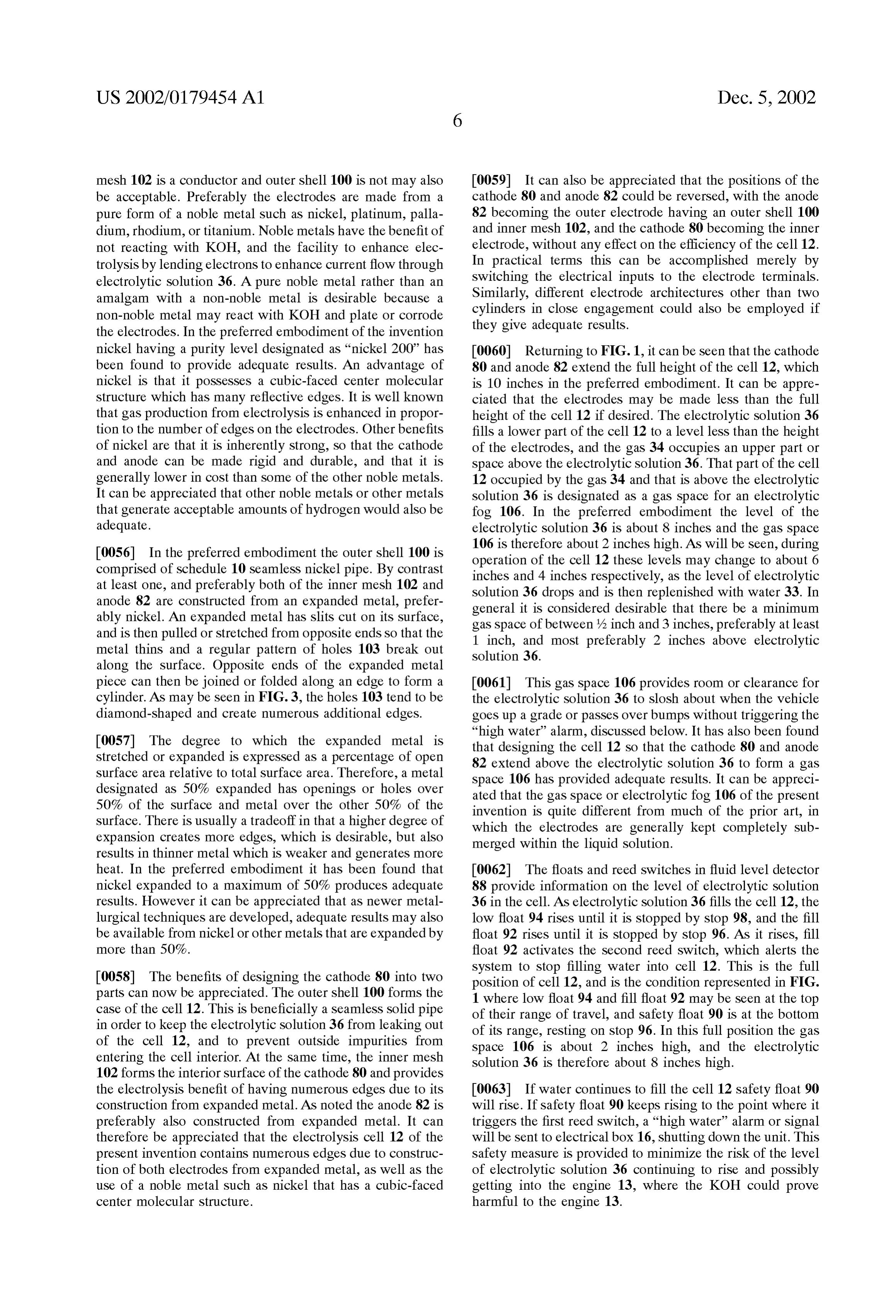
Surface. There is usually a tradeoff in that a higher degree of invention is quite different from much of the prior art, in which the electrodes are generally kept completely Sub expansion creates more edges, which is desirable, but also merged within the liquid Solution. results in thinner metal which is weaker and generates more heat. In the preferred embodiment it has been found that 0062) The floats and reed Switches in fluid level detector nickel expanded to a maximum of 50% produces adequate 88 provide information on the level of electrolytic solution results. However it can be appreciated that as newer metal 36 in the cell. As electrolytic solution 36 fills the cell 12, the lurgical techniques are developed, adequate results may also low float 94 rises until it is stopped by stop 98, and the fill be available from nickel or other metals that are expanded by float 92 rises until it is stopped by stop 96. As it rises, fill more than 50%. float 92 activates the second reed Switch, which alerts the system to stop filling water into cell 12. This is the full 0058. The benefits of designing the cathode 80 into two position of cell 12, and is the condition represented in FIG. parts can now be appreciated. The outer shell 100 forms the 1 where low float 94 and fill float 92 may be seen at the top case of the cell 12. This is beneficially a SeamleSS Solid pipe of their range of travel, and safety float 90 is at the bottom in order to keep the electrolytic Solution 36 from leaking out of its range, resting on Stop 96. In this full position the gas of the cell 12, and to prevent outside impurities from space 106 is about 2 inches high, and the electrolytic entering the cell interior. At the Same time, the inner mesh solution 36 is therefore about 8 inches high. 102 forms the interior surface of the cathode 80 and provides the electrolysis benefit of having numerous edges due to its 0063) If water continues to fill the cell 12 safety float 90 construction from expanded metal. AS noted the anode 82 is will rise. If safety float 90 keeps rising to the point where it preferably also constructed from expanded metal. It can triggers the first reed Switch, a “high water alarm or Signal therefore be appreciated that the electrolysis cell 12 of the will be sent to electrical box 16, shutting down the unit. This present invention contains numerous edges due to construc Safety measure is provided to minimize the risk of the level tion of both electrodes from expanded metal, as well as the of electrolytic Solution 36 continuing to rise and possibly use of a noble metal Such as nickel that has a cubic-faced getting into the engine 13, where the KOH could prove center molecular Structure. harmful to the engine 13.
Page 13
US 2002/0179454 A1 Dec. 5, 2002
0064. It can also be appreciated that when 11 vehicle tend to drip down through conduit 108 back into the elec climbs a grade or passes over bumps, the resultant Sloshing trolytic solution 36 in the cell 12. It can be appreciated that about of electrolytic solution 36 may cause safety float 90 to a different material may also be used to construct condenser rise. Since it is not desired for this type of activity to trigger 15 provided that, like Stainless Steel, it has a Surface con a “high water alarm, fluid level indicator 88 is preferably ducive to condensing water vapour and is preferably a heat mounted in the center of the upper surface of cell 12. This conductor.
arrangement may help avoid false alarms because when the 0070. At the top of cell 12 is the upper block 78, which vehicle climbs a grade the rise in liquid level is more likely is another polyethylene block Similar to those discussed to be observed towards the periphery of cell 12 rather than earlier. As before, the lower Surface of upper block 78 will at the center.
preferably be etched with a circular channel to fit the 0065. As the cell 12 continues in operation the level of cylindrical upper edge of condenser 15. Upper block 78 has electrolytic solution 36 drops, causing fill float 92 to drop a conduit 110 leading to a pressure Switch 112, which is a until it comes to rest at stop 98, followed by low float 94 preSSure Sensor Set to trigger at a predetermined Safety dropping and eventually triggering the third reed Switch. release pressure of 35 lbs in the preferred embodiment. Upon this event a signal will be sent calling for a refill. AS There is an anode terminal 114 in the form of a threaded, will be discussed in greater detail, a refill involves water 33 Solid nickel rod. As seen in FIG. 1, anode terminal 114 from the water reservoir 14 entering the cell 12 through inlet extends from above the top surface of upper block 78 down or water conduit 50 until fill float 92 rises to trigger the through the condenser 15 and separator block 76 to the Second reed Switch. anode 82, with which it makes contact. Further in upper block 78 there is a conduit 116 connected to a hose 118 0.066. In the event that refill does not occur, the level of which carries gas 34 directly into manifold 64. There is also electrolytic solution 36 will continue to drop until the fourth a conduit 120 which carries gas 34 into manifold 64 through reed switch is activated by low float 94, which will trigger a hose 122 and a flow regulator 124. The flow regulator 124 a “water low” signal shutting down the unit. This event will is operatively connected between the cell 12 and the intake also turn on the red “water low 1.e.d. 27 on the electrical box 16, providing a visual indication to the vehicle operator of engine 13, and regulates the flow of gas 34 from cell 12 to engine 13 according to the preSSure at the air intake of that unit 10 has stopped operating due to a “water low” engine 13. In the preferred embodiment, the flow regulator condition. The unit is shut down upon this condition being is a pressure release valve in the form of a check valve 124 reached because attoo low a level the concentration of KOH in electrolytic Solution 36 becomes disproportionately high, set at 20 lbs pressure. As shown in FIG. 1, check valve 124 which could in turn lead to the generation of an unacceptable is preferably mounted on the outside of manifold 64 at the entry point of hose 122.
amount of heat. As described further below, under this condition the unit may be brought back online by the 0071. The check valve 124 is set to release gas 34 to the operator performing a manual refill. engine 13 upon the gas 34 reaching and just exceeding a release pressure, or 20 lbs in the preferred embodiment. AS 0067. It can be appreciated that fluid level detector 88 will be discussed, this pressure is towards an upper end of provides the feedback necessary to keep the level of elec an operating range of preSSures at the air intake of engine 13. trolytic Solution 36 within a safe and efficient working range, It can be appreciated that other types of flow regulators than including Shutting down the System when the level gets preSSure release valves may also be used as long as they can either too high or too low. suitably regulate the flow of gas 34 to the engine 13. 0068 The separator block 76 fits on top of cell 12, and is 0072 Turning now to manifold 64, an internal conduit preferably a polyethylene block similar to lower block 38 126 is shown to provide a functional representation of the discussed earlier. Accordingly, circular channels are prefer circulation of gas 34 through the manifold 64. Internal ably etched into the upper and lower Surfaces of Separator conduit 126 connects with hose 62 coming from water block 76, to form a Snug fit with the cylindrical edges of reservoir 14, hose 118 coming from cell 12, hose 122 condenser 15 and cell 12, respectively. Separator block 76 coming from cell 12 through check valve 124, and with gas has an internal conduit 108 that acts as an outlet to receive output hose 31 which goes to external Solenoid 30. It may be gas 34 produced in cell 12, allowing gas 34 to rise from the noted that internal conduit 126 makes possible a gas con electrolytic fog 106 to the condenser 15. Conduit 108 should nection conduit connecting gas 34 from cell 12 to water be wide enough to allow gas 34 to flow without undue reservoir 14 through hoses 118 and 62. restriction, but also narrow enough So that Separator block 0073 Manifold 64 also has a safety release valve or 76 functions as a heat insulator between the cell 12 and condenser 15. In the preferred embodiment adequate results safety solenoid 128 and a fill solenoid 130 that indepen have been obtained for the conduit 108 having a diameter of dently and in parallel open or close access between internal about /2 inch. conduit 126 and gas output hose 31. Similarly, there is a water reservoir Solenoid 132 that opens or closes acceSS 0069. The condenser 15 is a seamless stainless steel between hose 62 coming from the water reservoir 14 and cylinder about 3% inches in height and 4 inches diameter. hose 118 going to cell 12. In FIG. 1 Solenoids 128, 130, and Due to the physical Separation provided by the Separator 132 are represented for illustration purposes as Valves, Since block 76, condenser 15 thermally isolates gas 34 in its functionally their effect is to open or close a path for the gas interior, keeping it approximately 10 C. cooler than the gas 34 to flow within internal conduit 126. It can also be seen 34 in the electrolytic fog 106 of cell 12. The effect of the from the figure that manifold 64 contains a pressure Switch temperature differential is that much of the moisture being 134, pre-set at 11 lbs, and a pressure Switch 136, which is a carried by gas 34 will condense and form water droplets on preSSure Sensor pre-Set at a predetermined Safety release the interior walls of the condenser 15. These droplets will pressure of 40 lbs.
Page 14
US 2002/0179454 A1 Dec. 5, 2002
0.074. It may be seen from FIG. 1 that pressure Switches 12 to which they are attached to the case 18. Electrically, the 134 and 136 are directly connected to hose 62 carrying gas connection of cathode 80 through case clamps 145 and 147 34 from water reservoir 14. Therefore, while in the preferred to the case 18, which in turn is attached to the body of the embodiment these pressure Switches are mounted on mani vehicle, means that the cathode 80 will acquire the “negative fold 64 for convenience, functionally they respond to the ground” that is Standard for most vehicles. preSSure of gas 34 in water reservoir 14 and are unaffected 007.9 FIG. 2 also shows two power conditioning means by the setting of water reservoir Solenoid 132. Similarly, or power supplies 144 attached by case clamp 143 to the side while hose 122 carries gas from the cell 12 through check of water reservoir 14. The power supplies 144 are are valve 124 to the manifold 64, as shown in FIG. 1, the output standard 10-16 volt type, DC to DC converters that step-up past check valve 124 is otherwise connected directly to gas current and step-down Voltage. Each power Supply 144 output hose 31, and is unaffected by the Setting of exhaust receives approximately 6.9 amperes of current at 11.1 Volts Solenoid 128 or fill Solenoid 130.
from the electrical box 16, and outputs a stepped-up current 0075). In FIG.1, the internal configuration of manifold 64 of approximately 23.9 amperes by Stepped-down voltage of is represented in functional terms for clarity of illustration, 2.4 volts to the electrodes of cell 12. The electrical input to and does not necessarily represent the actual internal mecha the cathode 80 is made at case clamp 145, and to the anode nism of manifold 64. It can be appreciated that a perSon 82 at anode terminal 114. Since case clamp 145, and skilled in the art should be able to readily construct a therefore cathode 80, is held at the vehicle's electrical functionally equivalent manifold based on the components ground, power to the electrodes is essentially provided at the and functional descriptions provided. In the preferred anode 82. It can also be appreciated that while the current embodiment of the invention it has been found that Sole and Voltage output of power Supplies 144 provide adequate noids Specially constructed to control the passage of hydro results, other embodiments of the invention may obtain gen, manufactured by the Burkert Company of Germany, adequate results from different current and Voltage configu provide adequate results. rations.
0.076 FIG. 1 further shows gas output hose 31 connected 0080. The water reservoir 14 as noted is preferably to external Solenoid 30. External Solenoid 30 is a Switchable constructed of a strong, heat conducting material Such as valve in the form of a three-way Solenoid that has at least Stainless Steel. In the preferred embodiment the water res two positions. External Solenoid 30 can be set to connect gas ervoir 14 receives two coats of an insulating Spray made output hose 31 to either the engine 13 through gas output from a ceramic compound, Such as the type manufactured by hose 32 and a check valve 138 in one position, or to vent to Envirotrol, Inc. of California, U.S.A. The spray distributes a the atmosphere through gas output hose 35 and a check layer of insulation approximately 2%000 of an inch thick over valve 139 in another position. Check valves 138 and 139 are the exterior Surface of the water reservoir 14. The insulation each Set at /10 lb, and Serve primarily to prevent any outside provided by this material has been found to provide an air from entering and possibly contaminating the cell 12. adequate degree of heat retention. The entire Surface of External Solenoid 30 is set as appropriate by the electrical water reservoir 14 is sprayed except for a vertical Strip 142 box 16 through the connection provided by Solenoid lead 28. about 2 inch wide which is left as exposed metal. Generally, external Solenoid 30 will be set to connect to the 0081. In addition to providing electrical power to run the engine 13 through gas output hose 32 when the device 10 of cell 12, the power Supplies 144 also Serve a dual purpose of the present invention is operating and generating gas 34, and acting as a heater for water reservoir 14. This is accom will be set to vent to the atmosphere through gas output hose plished by mounting the two power Supplies 144 on water 35 when the device 10 is being shut down, and it is desired reservoir 14 So that a portion of their metal Surface contacts to purge gas from the System. AS noted, gas output hose 32 the exposed metal strip 142. In this way the heat naturally may be conveniently attached to the intake manifold of the generated by power Supplies 144 is transmitted to the engine at a plug input precast to receive auxiliary hoses. stainless steel Surface of water reservoir 14. The insulation 0077. In the preferred embodiment of the invention gas that otherwise covers the surface of water reservoir 14 helps retain the transmitted heat inside water reservoir 14.
output hose 31 and gas output hose 32 have a diameter of about ys inch. It is preferred that the diameters of the other 0082 The benefit of this arrangement of power supplies hoses in the system such as hoses 62, 118, and 122, as well 144 is that it provides heat to melt ice that may form inside as the various internal conduits also be approximately ys water reservoir 14 when the vehicle is left turned off for an inch to facilitate convenient coupling between components. extended period in freezing weather. The ice must be melted It can be appreciated that other embodiments of the inven to free up water 33 so it is available when needed to refill tion may use hoses having a different diameter, that may be electrolytic solution 36 in cell 12. The heat provided by more appropriate for Systems operating at different gas power Supplies 144 provides adequate results in this respect. preSSure or production levels. In the most extreme case, where the water level inside water reservoir 14 is at the maximum fill level 74 and freezes into 0078 FIG. 2 shows the elements of the device 10 of the a solid block of ice, the heat from power supplies 144 in the present invention from the same front view as that shown in preferred embodiment has been found to melt the block of the functional cut-away view of FIG.1. The water reservoir ice and restore the water 33 to liquid form in a reservoir 14, electrolysis cell 12, polyethylene blocks 38,54, 76, and melting time of approximately two hours. 78, manifold 64, and various hoses connected to the mani fold 64 that were described above may be seen. FIG. 2 also 0083 FIG. 2 also shows a metal jacket or heat blanket shows a case clamp 143 attached to the water reservoir 14, 146 on the outside surface of the cathode 80 of electrolysis and case clamps 145 and 147 attached to the cell 12. These cell 12. The heat blanket 146 is a stainless steel sheet with three case clamps Securely hold the water reservoir 14 or cell an internal filament of conducting wire. When current is
Page 15
US 2002/0179454 A1 Dec. 5, 2002
applied to the wire, heat from the wire is transmitted to the 0088. Thermodisc 152 attaches to separator block 76 in metal jacket, which distributes the heat over the wider area. order to monitor the overall ambient temperature, and is The heat blanket 146 is provided to warm up the cell 12 in electrically connected in the main circuit containing oil extremely cold weather. While the electrolytic solution 36 pressure lead 26. This thermodisc is set to 80° C., and will has a lower freezing temperature than the freezing point of open and thereby shut down the device 10 upon a general water and does not actually freeze Solid in Such weather, it ambient temperature of 80 C. being reached inside the case does tend to thicken to Some extent. It has been found that 18. The temperature of 80 C. is selected for system shut when electrolysis is attempted in these circumstances the down because at this high temperature the electrical com current demand required to effect electrolysis increases ponents may cease to function properly and the polyethylene measurably. This current demand imposes a significant drain blocks may even change shape.
on the vehicle's electrical System, and may damage the regulator inside the alternator. 0089 FIG. 2 also shows threaded rods 154 and nuts 156 connecting the lower block 38 with upper blocks 54 and 78, 0084. In order to avoid the risk of damage to the alter and with separator block 76 of the cell 12. Since FIG. 2 nator, in the preferred embodiment of the invention when shows one side of the unit 10, it can be appreciated that the ever the temperature of the cell 12 is less than a predeter water reservoir 14 and cell 12 each have four threaded rods mined cold temperature of -10 C. at Start-up, output power 154, two on each side. The threaded rods 154, nuts 156, and from electrical box 16 is directed to the heat blanket 146 other associated hardware not shown Such as flat washers rather than to the power supplies 144. The heat blanket 146 and flanges are used to Securely and tightly hold together the is designed to draw the same power as cell 12, So there will elements of the water reservoir 14 and cell 12. In the be no inordinate drain on the vehicle's electrical System. preferred embodiment of the invention the Specifications After the unit has operated for Some time and the tempera governing the threaded rods 154 and other such hardware ture of cell 12 rises above -10 C., the current from have been designed to conform to the American Society of electrical box 16 is redirected to the power supplies 144 and Mechanical Engineers standard number B31.1 for pressure electrolysis can begin. It has been found that in the preferred vessels. The apparatus 10 of the present invention is a embodiment, a start-up at -40°C. takes about 45 minutes to preSSure vessel Since it is a container that encloses a gas reach -10° C. Since electrolysis is an exothermic reaction under preSSure.
which puts heat into the electrolytic solution 36, for the duration of the time that the vehicle 11 is running and the 0090 This professional engineering standard specifies device 10 is operating the temperature of cell 12 should the various design parameters that affect the ability of the continue to rise and not fall below -10° C. Therefore if the preSSure vessel or container to withstand an internal buildup heat blanket 146 is needed, it will generally only be at the of pressure and an explosion. This includes the use of beginning of a trip and for a limited time. threaded StainleSS Steel rods 154 and their positioning at 0085 Temperature detection in selected locations is corners of the vessel, the use of flat washers under each nut obtained through the use of temperature Sensors, preferably 156, lock washers to withstand vibration, and other factors in the form of thermodiscs. These devices contain a Snap Such as the type and number of components, their tensile action bimetal disc that can open or close an electrical Strength, and Weld integrity. This is a fairly rigorous Stan connection upon a pre-Set temperature being reached. They dard, and is generally applied for preSSure vessels that are will re-set, that is return to closed if open, or return to open over 6 inches in diameter and that operate at about 30 if closed, upon the temperature reverting back to the other pounds pressure. Since the present invention has a diameter Side of the pre-Set value. It has been found that the Sensors of about 4 inches and operates at a pressure less than 30 lbs, manufactured by Elmwood Sensors of Rhode Island, U.S.A. it can be appreciated that use of this preSSure vessel Standard for this purpose produce adequate results. provides an added measure of Safety. According to the standard, the threaded rods 154 should be able to withstand 0.086 The thermodiscs are placed in the location where 14,000 lbs of pressure before coming apart. temperature detection is desired, and are connected electri cally in the circuit of the device being monitored. There are 0091 By way of comparison, as was noted above the three thermodiscs shown in the preferred embodiment of apparatus of the present invention already includes Safety FIG. 2. Thermodisc 148 attaches to lower block 38 in order venting features that release pressure at much lower levels of to monitor the ambient temperature around fan 20, and is 35, 40, and 60 lbs. Further, the individual components of the accordingly connected electrically in the Same circuit as fan invention 10 also have preSSure ratings. The hoses Such as 20. This thermodisc has a set temperature of 15 C., and will gas output hoses 31 and 32, and hoses 62 and 118 are rated open the circuit driving fan 20, thereby Stopping rotation of at about 120 lbs, the polyethylene blocks 38,54, 76, and 78 the fan, when the detected temperature drops below 15 C. are rated at about 6,000 lbs, the stainless steel cylinders of In cool weather the additional cooling provided by fan 20 is the condenser 15 and water reservoir 14 are rated at about generally not needed. 14,000 lbs, and the nickel cell 12 is rated to withstand about
0087. Thermodisc 150 attaches to outer shell 100 in order to monitor the temperature of cell 12, and is placed in the 0092 An explosion might occur in the device 10 if a circuit driving the heat blanket 146. Its set temperature is Spark is introduced, or possibly due to internal compression -10° C. Accordingly, when the detected temperature drops if the pressure inside cell 12 should somehow rise to the below -10° C. thermodisc 150 closes, thereby directing range of a few hundred lbs. In view of the much higher current into heat blanket 146. When the temperature rises preSSure ratings of the materials and the preSSure vessel above the set point, thermodisc 150 opens and current is Standards of construction, Such an explosion would likely be redirected to the power Supplies 144 that Supply the elec completely contained internally and would not lead to any trodes of cell 12. external damage or harm.

Page 16
US 2002/0179454 A1 Dec. 5, 2002
0093. The electrical box 16 as noted connects with posi 0098. The operation of the present invention can now be tive lead 22 and negative lead 24 directly from the vehicle described. Initially, when the vehicle 11 is parked and the battery, oil preSSure lead 26 directly from the oil pressure engine 13 is turned off, there is no power to the cell 12, no Switch, and has an electrical output 28 to external Solenoid electrolysis, and no gas 34 or gas pressure present in the 30. There are other electrical connections, not shown, system. When the vehicle operator turns the key to start the between the electrical box 16 and the cell 12, Such as a engine, the oil pressure Switch of the vehicle is activated, power out line carrying power to the power Supplies 144, as typically as a 12 volt Signal. This simultaneously raises oil well as lines connecting with the various pressure Switches, pressure lead 26 from Zero to 12 volts, which trips a low fluid level detectors, and rupture disk 60. current relay that in turn closes the large Solenoid inside electrical box 16.
0094. The power received from the battery on positive lead 22 and negative lead 24 is approximately 12-13 Volts at 0099. At start-up, prior to directing power to the power 15 amperes, or 195 watts. The power out line carries supplies 144, the circuits inside the electrical box 16 auto approximately 11.1 volts at 6.9 amps or 76 watts to each matically check the various pre-conditions to Safe operation power supply 144, for a total of about 152 watts. Each of the of the device 10. Since the electronics are analog, this power supplies 144 output 2.4 volts at 23.9 amperes for a preliminary check occurs essentially instantaneously, and total of about 57 watts, or 114 watts total. It can be consists of detecting either the presence or absence of appreciated that these power figures may vary as appropriate Signals associated with each particular pre-condition. The for other embodiments of the present invention. Signals to be monitored therefore include those associated 0.095 The internal components of electrical box 16 with: thermodisc 152 on separator block 76, to confirm that include a single large Solenoid used to Start up the cell 12, the unit is not already at a high temperature above 80 C., the and Several relays and fuses, all operating at Vehicle Standard first reed Switch triggered by safety float 90 and the fourth 12 volts. When the vehicle engine is started, oil pressure lead reed switch triggered by low float 94 in cell 12, to confirm 26 triggers a relay which activates the large Solenoid, that the level of electrolytic solution 36 is neither too high connecting the power input from the battery to the line out or too low respectively, pressure Switch 136, to confirm that to the power Supplies 144. For the operator's convenience, the System is not already pressurized above 40 lbs, and the the outside of electrical box 16 includes on/off Switch 21, reed switch associated with rupture disk 60, to confirm that bypass Switch 23, the green “system operating 1.e.d. 25, and the rupture disk 60 has not ruptured. If any of these the red “water low” le.d. 27. Electric box 16 of the preferred conditions are confirmed as having occurred the System will embodiment also contains an hour-metre, which records the not start and electrolysis will not take place. duration of time that the unit 10 is operating. 0100 Further start-up monitoring includes thermodisc 0096. It can accordingly be appreciated that the device 10 148 on lower block 38. If this thermodisc triggers, indicating of the present invention presents a very clean and Simple a temperature under 15 C., the fan 20 will not activate. If interface with the vehicle operator. The device operates the temperature is -10° C. or colder, thermodisc 150 on cell automatically and does not require any active intervention 12 will trigger, informing the System to activate the heat by the operator while he or She is operating the vehicle. blanket 146 rather than power supplies 144. Accordingly, there is no need for an operator panel any where inside the vehicle. The operator can turn the device 10 0101 If there are no disabling conditions electrical box on or off using on/off Switch 21, or use the bypass Switch 23 16 sets external Solenoid 30 to output through gas hose 32 to perform a manual refill, as described below. When lit, the to engine 13. Electrical box 16 also delivers power to the green 1.e.d. 25 provides reassuring feedback that the device power Supplies 144, which regulate the current and Voltage 10 is operating correctly. Otherwise, when this 1.e.d. is out and deliver power to the electrodes through anode terminal it is an indication that the device 10 is not operating and 114 and the cathode 80. If thermodisc 150 has been acti there is no electrolysis. The red 1.e.d. 27 when lit indicates vated, heat blanket 146 will receive the power from elec a “water low” situation, alerting the operator to refill the trical box 16 until the temperature rises above -10° C., at water reservoir 14 and initiate a manual refill. which time thermodisc 150 will re-set and power will be redirected to power Supplies 144. Once power is received by 0097. It can further be appreciated that the durability of power Supplies 144, electrolysis commences inside cell 12 the unit 10 is enhanced by its construction from durable and hydrogen and oxygen gases of gas 34 are generated. It materials. Such as nickel, Stainless Steel, and ultra high can be appreciated that upon operation of power Supplies molecular weight polyethylene blockS. The electrical com 144 the heat generated will automatically be transmitted to ponents are simple and reliable analog devices Such as water 33 in water reservoir 14, to melt water 33 if it is Solenoids, relays, and fuses, operating at the industry Stan frozen. In this way the present invention makes productive dard 12 volts. There are no digital electronic or program use of the heat from the power supplies 144 that would mable components in the present invention, because Such otherwise be dissipated without providing any benefit to the components would add complexity and cost, and may be System.
more likely to break down due to temperature Sensitivity or programming errors. Further, there are no moving parts in 0102 Turning now to the configuration of manifold 64, in the cell 12 and kit of the present invention. Accordingly, it the ordinary course safety Solenoid 128 and fill Solenoid 130 can be appreciated that the present invention is well Suited are both held closed, thereby blocking any gas 34 in the to operate reliably for extended periods, particularly in the internal conduit 126 and cell 12 from access to gas output hostile road environment where Service technicians are hose 31. Water reservoir Solenoid 132 is held open, so there generally unavailable. When Servicing is required, the is a direct connection from cell 12 to water reservoir 14 simple design of the device 10 should allow repair and through hose 118, internal conduit 126, and hose 62. As the maintenance procedures to be relatively Straightforward. cell 12 generates gas 34, the gas 34 will fill the upper parts
Page 17
US 2002/0179454 A1 Dec. 5, 2002
of cell 12 and water reservoir 14, building up the gas 0107 When operating in the steady state, the cell 12 pressure inside the device 10 from its initial zero level. Since generates approximately 600 ml of hydrogen and oxygen the space enclosed by cell 12 and water reservoir 14 is fixed gases per minute, which has been found to produce adequate or predetermined in Volume, it can be appreciated that as results when delivered to the vehicle engine 13. more gas 34 is produced the preSSure inside this space 0108. The device 10 of the present invention produces a increases with time. When the pressure of gas 34 just reasonable quantity of gas within a compact space due to the exceeds the release pressure of 20 lbs, gas 34 will be various features that enhance the electrolysis process. These released by the flow regulator or 20 lb check valve 124 include the use of the metal nickel, and in particular the through hose 122 to gas output hose 31 and gas output hose expanded form of the metal used for both the cathode 80 and 32 to the engine 13. Accordingly, during this steady State anode 82, which increases the number of edges available for operation of the device 10, gas 34 flows from the cell 12 to electrolysis. Gas production is also enhanced in the present the engine at about 20 lbs preSSure, and the cell 12 and water invention due to the use of regulated input power that reservoir 14 are equalized at about this Same 20 lbs pressure. provides a higher current flow into the electrodes. It is well 0103). It has been found that it generally takes about 4-5 known that gas production from electrolysis increases with minutes for the system to pressurize from Zero to 20 lbs. current. The approach taken by the present invention may be Therefore, the operator of the vehicle may experience a contrasted with Some of the prior art, in which a unregulated noticeable increase in power approximately five minutes power was provided from the battery directly to the cell, and after the engine is Started. AS discussed in greater detail was considered desirable for its simplicity. However, this below, the System should in the ordinary course remain resulted in low current levels which required compensation operating and provide the benefits of electrolysis throughout through adjustment of the electrolytic Solution. In turn, this the rest of the trip. created a problem of excessive heat, which led to a need for 0104. During operation of the cell 12 an ample amount of more elaborate cooling or pressurization. Therefore, the heat is generated which tends to reduce the efficiency of the apparent Simplicity of a direct battery to cell connection is electrolysis process. On its own, the temperature of the gas undermined by the complexity of Systems required to com 34 will generally reach about 75 C. in the gas space 106 of pensate for the Shortcomings of that approach. It can there cell 12, and about 10 C. less, or 65 C., in the condenser 15 fore be appreciated that by regulating current, the present due to the thermal isolation provided by the separator block invention achieves adequate gas production using only the 76. Activation of the fan 20 pulls hot air down and out of the vehicle battery as power Source without requiring cumber case 18, cooling both the cell 12 and condenser 15 to about Some additions Such as a Specialized cooling System or extra 55 C. and 45 C. respectively. In cooler weather these alternator or generator.
temperatures will drop further. System cooling is also facili 0109 The gas produced includes a mixture of individual tated by the use of heat-conducting metal Such as nickel hydrogen and oxygen atoms as well as combination hydro rather than plastic for the cell 12. It can therefore be gen-oxygen bond pairs. While an individual gas could be appreciated that the cooling features provided contribute to Separated out if desired, it is believed that the presence of the efficiency of electrolysis. Further, unlike some of the both gases individually and in combination enhances the prior art, a separate cooling System is not necessary. combustion process occurring in the engine 13. It is also 0105. It has been noted that gas 34 generally contains believed that the passage of gas 34 through gas Space 106 Some quantity of moisture or water vapour. This can be a contributes to the effectiveness or combustible quality of the problem in cold weather, Since the water vapour may freeze gas 34.
and create blocks in the circulation of gas 34. In particular, 0110. It can now be appreciated how the device 10 of the ice particles may form in gas output hose 31 when warm gas present invention produces an adequate and effective 34 meets the cold outside temperature. If left to build up, a amount of hydrogen and oxygen gases to aid combustion. preSSure blockage could lead to a System breakdown or explosion. 0111. The cell 12 produces gas 34 at a rate determined by 0106 The risk is reduced in the present invention due to the current input to the electrodes, and by factors associated Several factors. First, Since moisture increases with heat, the with the design of the cell 12 itself, Such as the construction cooling features of the invention generally lower the mois of electrodes using expanded nickel arranged in a cylindrical ture level. Also, when the gas 34 reaches the condenser 15, configuration. Since these factors are fixed once the unit is the temperature differential between the condenser 15 and powered up, the Volume of gas produced by the cell 12 for cell 12 causes much of the moisture to condense and collect any given period of time will be a constant. In particular, the on the internal walls of the condenser 15. The collected rate at which gas 34 is produced by the cell 12 is independent water droplets will drip back down, through conduit 108, to of the operating factors of the engine 13, Such as its Speed cell 12. This reduces the amount of moisture carried by gas in rotations per minute (rpm) or air intake pressure. How 34 to gas output hose 31. Further, while gas 34 is flowing ever, the rate at which gas 34 is actually delivered to the inside gas output hose 31, freezing will not occur even in engine 13 will ordinarily be dependent to Some extent on the air intake pressure or Speed of the engine 13. By contrast, the extreme cold due to the movement of the gas. Therefore, a device 10 of the present invention has been designed so that heat trace to warm the output hose is not necessary. Addi in most operating circumstances the rate at which gas 34 is tionally, if external Solenoid 30 is mounted below the air delivered to engine 13 is constant. intake at engine 13, any moisture that is carried in gas output hose 31 will tend to collect at the bottom of external Solenoid 0112 The engines of certain vehicles such as tractor 30 rather than proceed to the engine. This moisture will trailer trucks of the type represented by vehicle 11, as well eventually get vented to atmosphere through gas output hose as Some passenger cars, are equipped with turbochargers. A 35 when the system shuts down. turbocharger essentially uses an impeller driven by exhaust
Page 18
US 2002/0179454 A1 Dec. 5, 2002
gas to pull in air from the outside and deliver it under the time, it follows that the rate of delivery or flow of gas 34 preSSure to the air intake port of the engine. AS the engine's into engine 13 will also be constant. It further follows that Speed or rpm increases, the force of the exhaust rises leading the effect of gas 34 on the efficiency of engine 13 will vary to faster rotation of the impeller and higher air pressure depending on the Speed of the engine. Since the flow of gas intake. This relationship is appropriate Since an increase in 34 is constant due to the flow regulator, the lower the engine rpm means there are more combustions in a given period of Speed, the higher the proportion of gas 34 in the combustion time. Air intake pressure therefore needs to rise in unison chamber. According to the present invention, the highest with rpm in order to Supply the greater quantity of air proportion of gas 34 occurs when the engine is idling. It is demanded for that Same given period of time. The large well known that internal combustion engines are less effi tractor-trailer type vehicles typically idle at about 600-800 cient and more polluting when operating at lower rpm, and rpm and 10-15 lbs pressure, and generally have an upper particularly when idling. By delivering a relatively higher range of about 1,800 rpm and 30 lbs pressure. proportion of hydrogen and oxygen to the combustion when 0113 FIG. 5 is a representative graph of pressure (P) at the engine is idling or at low rpm, the benefits of reduced an air-intake port of the engine 13 against time (t). It may be emissions are optimized.
understood that the air pressure (P) is essentially related to 0118. The delivery of gas 34 in a regulated flow allows the speed in rpm of the engine 13. Therefore in FIG. 5, as the present invention to be flexibly used with a wide variety the engine operates between a cold Start and a high rpm, it of vehicles and engine types. All that is required is to Set the can be seen that for this particular engine 13 air intake flow regulator or check valve 124 to a value that is sufficient preSSure P operates in a range of pressures between Zero and to overcome the typical air intake operating preSSure of the approximately 22 lbs. particular vehicle engine. Vehicles Such as passenger cars 0114 AS noted, gas output hose 32 carrying gas 34 from that don't use turbochargers may be well served with flow cell 12 enters engine 13 at the Same air intake port as that regulator 124 Set at just a few lbs, whereas more powerful used by the turbocharger. Therefore, if the air preSSure input turbocharged vehicles may require the check valve 124 Set from the turbocharger is greater by a certain extent than the at 25 lbs or higher. In general, a release pressure Set in a preSSure of gas 34 in gas output hose 32, the gas 34 may be range of 1 to 50 lbs should accommodate most vehicle types. effectively blocked from reaching the combustion chamber. It can also be appreciated that the approach of the present It can now be appreciated why the rate at which gas 34 is invention is more flexible than the prior art which relied on actually delivered to the engine 13 will ordinarily be depen the vacuum intake provided by a passenger car. That device dent to Some extent on the air intake pressure or Speed of the of the prior art could not work with turbocharged, preSSur engine 13. ized air-intake engines. By contrast, the device 10 of the present invention can work with any type of engine Since it 0115) In the present invention gas 34 is delivered to relies on a flow regulator operated within the device 10 engine 13 under pressure. In particular, Since gas 34 passes itself.
through a flow regulator in the form of a pressure release valve or check valve 124, which in the preferred embodi 0119) The present invention is able to provide gas 34 to ment is Set at 20 lbs, the gas will be delivered at a constant the engine 13 for relatively long and uninterrupted periods release preSSure of 20 lbs. This release preSSure for check of time. Since the only element that gets used up during Valve 124 was Selected because, as shown in the represen electrolysis is the water component of electrolytic Solution tative graph of FIG. 5, it is towards an upper end of the 36, the device 10 of the present invention includes a water operating range of pressures at the air intake. The expected reservoir 14 to hold a supply of water 33, and includes the air intake pressure from the turbocharger will be less than 20 means to refill electrolytic solution 36 in cell 12 with water lbs most of the time. Therefore, the gas 34 containing 33 from water reservoir 14. In most cases the cell 12 will be hydrogen and oxygen gases generated by cell 12 will in most refilled from water reservoir 14 automatically by the device circumstances be at a higher preSSure than the turbocharger 10, without any activity or even awareness by the operator. pressure, and will not be blocked from delivery to engine 13. In other circumstances a manual refill by the operator is This ensures a relatively constant flow of gas 34 into engine required.
13, even when the air intake pressure fluctuates due to 0120 When the engine 13 is started and the unit is first engine load. turned on, there is always a possibility that water 33 in water 0116 Gas 34 delivered under 20 lbs pressure from cell 12 reservoir 14 may be unavailable because it is frozen. As may be blocked if the turbocharger pressure rises to a level noted, the heat from power Supplies 144 should melt any ice above the release pressure of 20 lbs, perhaps 22-25 lbs. in water reservoir 14 in a reservoir melting time of about 2 However, Such circumstances will typically occur only hours or less. Therefore, according to the present invention, briefly. Even if there were a prolonged period of high enough replacement water to replenish the electrolysis cell preSSure, as preSSure continues to build up in cell 12 it will 12 is made available at or before the reservoir melting time. become high enough to overcome the higher preSSure level. 0121 To ensure that cell 12 can fully operate until melt However, Such delayS will generally be infrequent, Since the water becomes available, the device 10 ensures that the invention Specifically delivers gas 34 at a constant pressure electrolytic solution 36 is at least at a level just above the that is towards the upper end of the operating range of third reed Switch of fluid level detector 88 at the time the unit preSSures at the intake, and therefore exceeds the expected is started. AS will be explained in greater detail below, this air intake pressure to engine 13 for all but the most extreme is accomplished by checking the level when the unit is being engine loads. shut down, and performing a refill at that time if necessary, 0.117) Since the production of gas 34 is constant, and so there will be sufficient electrolytic solution 36 at the since the gas 34 will be accessible to the engine 13 most of Subsequent start-up. Also, as previously noted, the device 10
Page 19
US 2002/0179454 A1 Dec. 5, 2002
will shut down if low float 94 drops to the level of the fourth Switch a signal is sent that resets fill solenoid 130 and water reed Switch. Therefore, at start-up the device 10 of the reservoir Solenoid 132 to their original closed and open present invention will have at minimum an amount of positions respectively. This will restore the original gas flow electrolytic Solution 36 that occupies the Space between the arrangement, opening the path between the cell 12 and water third and fourth reed Switches of fluid level detector 88. This reservoir 14, and compelling gas 34 from the cell 12 to go amount is most preferably enough to last for a minimum through flow regulator 124 to reach engine 13. There will be operating time that is longer than the reservoir melting time a slight delay as cell 12 rebuilds the 6 lbs of pressure that it of about 2 hours, and in the preferred embodiment there is lost. When the pressure reaches 20 lbs regular flow to the sufficient electrolytic solution 36 to last for over 6 hours. engine 13 will resume. In this way, a Sufficient amount of 0122) It can be appreciated that the scenario described water 33 is provided to replenish the electrolytic solution 36 in cell 12.
above is a worst case, and that it is more likely that the level of electrolytic solution 36 will be at least somewhat higher 0127. In the preferred embodiment of the invention the than the third reed switch at the time of start-up. Of course, volume of water contained in cell 12 between the second and as described above even the worst case Scenario can be third reed switches is only about 100 milliliters (/10 of a readily accommodated by the present System. Furthermore, liter). This is a fairly Small amount, and it suggests that once Since freezing conditions occur primarily in certain geo water 33 starts to flow the refill will be completed fairly graphic locations and during winter, the operator will gen quickly. The rate of fill may also be somewhat faster where erally be aware of the possibility that water 33 may freeze. there is a higher level of water 33 in the water reservoir 14, Accordingly, if the operator is So inclined, when the vehicle since that will increase the pressure above check valve 52. Stops for an extended period in freezing weather the operator 0128. The pre-condition that there be 11 lbs of pressure could open tap 44 and drain the water 33 out of water in water reservoir 14 is needed to ensure that there is at least reservoir 14 to eliminate the possibility of a frozen block a minimum sufficient pressure to drive water 33 into cell 12. when the vehicle 11 is restarted. The operator would have to At 11 lbs, in order to overcome 6 lb check valve 52, the remember to refill the water reservoir 14 before restarting engine preSSure would have to drop to 5 lbs. This is about as the vehicle 11.
low as the preSSure may get while the vehicle is being 0123. During operation of the vehicle 11 the device 10 of driven, and is a pressure that does not use the turbo boost the present invention will automatically refill electrolytic provided by the turbocharger. In that case, there may be a Solution 36 with water 33 from water reservoir 14. This refill delay in refill until Such time as the vehicle is idling or operation is fairly rapid and automatic, and requires no otherwise travelling at a Slow speed, It can therefore be action by the operator. appreciated that by imposing the minimum requirement of 0.124. The refill operation is initiated when low float 94 in 11 lbs pressure, the device 10 of the present invention ensures that it does not call for a refill when the water fluid detector 88 drops to the point where it triggers the third reservoir 14 is unable to deliver it because it is not pressur reed Switch. As a precondition for refill to occur, the System ized sufficiently.
requires that the pressure in water reservoir 14 be a mini mum of 11 lbs. This information is provided by pressure 0129. Check valve 52 is positioned in conduit 50 because Switch 134, which as noted is pre-set to trigger at 11 lbs. If there is always a latent pressure provided by the column of this condition is met, fill solenoid 130 is opened and water water 33 in water reservoir 14. If there were no check valve reservoir Solenoid 132 is closed. This connects cell 12 52, water 33 might on occasion flow Spontaneously into cell directly with the engine 13 (through /10 lb check valve 138), 12.
and blocks the connection between cell 12 and water reser voir 14. Just prior to these changes effected by the fill signal, 0.130. It can be appreciated that other values of pressure the gas pressure in cell 12 and water reservoir 14 had been Switch 134 and check valve 52 may be selected to better accommodate the flow of water 33 in device 10. For equalized at about 20 lbs. As a result of the changes brought example, pressure switch 134 could be set at 15 lbs and about by the fill Signal, the pressure in cell 12 drops rapidly to the generally lower pressure environment of engine 13, check valve 52 at 10 lbs. These particular values were not while the original higher 20 lbs pressure level previously Selected for the present embodiment due to inconsistent tolerance in the manufacture of the 20 lb check valve 124.
present is preserved in water reservoir 14. It can be appreciated that as the manufacturing tolerance 0.125 Since there is now a high pressure of about 20 lbs improves, other pressure values for these elements may in gas 34 of water reservoir 14, and a lower pressure in gas become acceptable.
34 of cell 12, the water 33 in water reservoir 14 is urged to 0131) Using the settings and container sizes of the pre flow into cell 12 through conduit 50. However, due to the 6 ferred embodiment of the present invention, it has been lb check valve 52 in conduit 50, water 33 will not flow until found that the vehicle 11 can operate for approximately 180 the pressure differential is at least 6 lbs. Therefore, upon hours where the cell 12 contains electrolytic solution 36 up pressure in cell 12 dropping to about 14 lbs or less, water 33 to the full level of the second reed Switch, and where water will flow into cell 12 through conduit 50, thereby refilling 33 in water reservoir 14 is at the maximum fill level 74. This cell 12. The pressure in cell 12 therefore does not have to time period represents approximately 150 hours from the drop to Zero, only to a point about 6 lbs less than the preSSure water 33 stored in water reservoir 14, and another 30 hours in water reservoir 14.
from the electrolytic solution 36. Within the cell 12, the 0.126 AS refill occurs, the level of electrolytic solution 36 device 10 will run for approximately 24 hours from a full rises, in the process raising first low float 94 and then fill position (second reed Switch) until it calls for a refill (third float 92. Refill will continue until fill float 92 rises to the reed Switch), and as noted it may run for about another 6 level of the Second reed Switch. Upon triggering of this reed hours before shutdown is imposed (fourth reed switch).
Page 20
US 2002/0179454 A1 Dec. 5, 2002
0132) If the operator forgets to refill the water reservoir first safety feature relates to the level of electrolytic solution 14 then the device 10 may well run out of water 33, and low 36 in cell 12. The highest level to which the electrolytic float 94 may drop to the fourth reed Switch, triggering a solution 36 is preferred to rise is to the second reed switch, Signal shutting the System down. This signal causes power to located just under stop 96 on fluid level detector 88, to form the power Supplies 144 to be cut off, Stopping any further the gas Space 106. Additionally, if due to a malfunction in electrolysis. Safety Solenoid 128 will open and external the water refill operation or for any other reason the level of Solenoid 30 will be set to vent, so that gas 34 in the cell 12 electrolytic solution 36 were to rise and reach condenser 15 and water reservoir 14 will vent to the atmosphere. The red and gas output hose 31, there is a risk that KOH from “water low' le.d. 27 on electrical box 16 will light up, electrolytic solution 36 could enter the air intake port of providing a visual indication to the operator that the System engine 13. This is undesirable, as KOH could cause damage has shut down because of low water. to the engine 13.
0133. This condition can be corrected by the operator. 0.137 Accordingly, the device 10 of the present invention Upon Shutting down the engine for 10 minutes as an includes safety float 90 and its corresponding first reed additional Safety measure to ensure that the System is Switch located on fluid level detector 88. If the level of depressurized, the operator will refill water reservoir 14 by electrolytic solution 36 in cell 12 rises above stop 96 and removing cap 29 and pouring in water until float 72 rises to continues to rise, safety float 90 will be pushed upwards the reed Switch, setting off a buzzer. Then the operator will until first reed Switch is triggered. The Signal generated by press and hold down bypass switch 23 on electrical box 16. the first reed Switch alerts the System to immediately per While the bypass Switch 23 is down, power is sent to power form an early shut down procedure. This involves cutting off Supplies 144, thereby re-activating electrolysis. Also, Safety power to power Supplies 144, to Stop any further electroly Solenoid 128 is closed and external Solenoid 30 is re-set to sis, opening Safety Solenoid 128 and water reservoir Sole direct gas 34 to engine 13 through gas output hose 32. Water noid 132, and setting external Solenoid 30 to vent to atmo reservoir Solenoid 132 remains open and the red “low water” Sphere through gas output hose 35. It can be appreciated that 1.e.d. 27 remains on. During this time gas 34 is being these steps will immediately depressurize both the cell 12 generated and the System is re-building internal preSSure. and water reservoir 14, and equalize them at atmospheric After several minutes the pressure in water reservoir 14 will pressure. This should prevent any further flow of water 33 reach 11 lbs, causing the green “system operating 1.e.d. to into cell 12, so that there will be no further rise in the level light up and the red “low water 1.e.d. 27 to turn off. At that of electrolytic Solution 36. In this case the operator cannot point the operator can release bypass Switch 23, and the restart the unit, and the unit will remain unavailable until it System will perform an automatic refill and resume normal is inspected and re-certified for Service by a qualified Service operation. technician.
0134) The present invention comprehends supplying 0138. The other safety features of the device 10 of the water to the device 10 approximately every 150-180 hours present invention relate to the risk of a buildup in preSSure of vehicle running time. It can be appreciated that the of gas 34. This could occur due to a variety of causes and amount of water to be Supplied, approximately 3.25 liters or may include, for example, an inadvertent crimping of a hose about 1/2 gallons, is reasonable and would not be particu or blocking of an internal conduit, or a situation where a larly demanding. In most cases there will already be Some Stone flies off the road and lodges in gas output hose 31. water 33 in water reservoir 14, so the amount to be supplied Regardless of the particular cause, any pressure buildup is a will be even less. Depending on the duty cycle of the vehicle cause for concern because of the risk of explosion that it 11, refills may be required as infrequently as once every 3-4 presents. The device 10 of the present invention accordingly weeks, or about once a month. For example, assuming a contains Several overlapping Safety features or preSSure work load of 10 hours a day, 6 days a week, a refill would relief means designed to Safely vent internal preSSure when be required only about once every 3 weeks. It can also be it reaches a predetermined Safety release pressure, before appreciated that water refills may be conveniently incorpo preSSure rises to a dangerous or excessive level. rated into regular vehicle maintenance. Accordingly, for most operators it is likely that running out of water 33 while 0139 Pressure switch 112 is built into upper block 78 and on the road and having to perform a manual refill will occur directly monitors the pressure inside cell 12. It can be only very infrequently, if at all. appreciated that Since water reservoir Solenoid 132 is usually 0135) It can now be appreciated how the device 10 of the kept open, pressure Switch 112 also in effect monitors the present invention operates to move gas 34 from the cell 12 pressure of water reservoir 14. The only time that cell 12 and to the engine 13, and water 33 from water reservoir 14 to cell water reservoir 14 will be at different pressure levels is when 12. Rather than relying on components Such as pumps that water reservoir Solenoid 132 closes to enable the system to have moving parts, as is frequently the case with the devices perform a water refill operation. Pressure Switch 112 is set taught by the prior art, the device 10 of the present invention to trigger at a predetermined Safety release pressure of 35 accomplishes this Same function using only the internal lbs, and comprises the first level of defence protecting the preSSure generated within the cell 12 by the electrolysis System from an undue rise in pressure. proceSS itself. Components Such as pumps invariably add 0140) If the pressure in cell 12 rises to 35 lbs, pressure cost, bulk, and complexity, and may be prone to breakdown Switch 112 sends a signal that causes safety Solenoid 128 to in very cold weather. Of course it can be appreciated that open. Safety Solenoid 128 acts as a gas bypass or Safety gas components Such as pumps may be used as appropriate in conduit that allows gas 34 in cell 12 to bypass the 20 lb other embodiments of the present invention. check valve 124 and connect to the lower preSSure environ 0.136 The operation of the various safety features of the ment of engine 13. As a result of this connection, the device 10 of the present invention may now be described. A pressure in cell 12 will decrease rapidly. When pressure
Page 21
US 2002/0179454 A1 Dec. 5, 2002
Switch 112 detects that the pressure is below 35 lbs, it sends 0146 While there is nothing wrong with allowing the a signal causing Safety Solenoid 128 to re-Set in a closed System to run itself down in this fashion, it is generally position, So that gas 34 returns to its regular flow through preferable to bring the System to a more orderly and proper check valve 124. Usually, the pressure in cell 12 will drop shut-down. Accordingly, in the preferred embodiment of the fairly rapidly by about 3-5 lbs before pressure Switch 112, invention a reed Switch is attached to rupture disk 60. The operating slower due to the inertia of its mechanical con reed Switch is connected to rupture disk 60 in such a way that Struction, is able to reset and respond. it sends a signal to electrical box 16 when rupture disk 60 0.141. This 35 lb pressure check is useful where there are blows. This signal alerts the system to cut off power to temporary blockages, Such as an ice chip or Stone that blockS power Supplies 144, Stopping further electrolysis, and to Set a hose temporarily and is then dislodged. It can be appre external Solenoid 30 to vent to atmosphere through gas ciated that the safety solenoid 128 may even activate several output hose 35. In addition, both le.d's 25 and 27 turn off, times in Succession, and that the act of repeated or inter providing a correct visual indication that the System is no mittent activation may itself help dislodge this type of longer working.
blockage. 0.147. It can be appreciated that the risk of a strictly 0142. A second level of defence against a rise in pressure mechanical element Such as the rupture disk 60 failing by is provided by pressure Switch 136. This pressure Switch is withstanding a rise in preSSure to the pre-set level is quite located on manifold 64 and directly monitors the pressure of low. Further, even if it does fail to rupture at the pre-set level, water reservoir 14, and indirectly, through open water res the mechanical strength of the rupture disk 60 will likely ervoir Solenoid 132, the generally equal pressure of cell 12. give way upon any further rise in preSSure. Accordingly, the In the embodiment of the present invention pressure Switch rupture disk 60 acts in effect as a “fail safe” backup in the 136 is pre-Set to a predetermined Safety release pressure of device 10 of the present invention. 40 lbs. 0.148 While it is highly unlikely that the system pressure 0143 A pressure rise to 40 lbs is considered serious will rise significantly above 60 lbs without triggering a enough to shut down the System. It is generally desirable built-in safety feature, the device 10 of the present invention however to first vent the pressurized gas 34. Accordingly, includes yet further Safety measures inherent in the design of upon triggering pressure Switch 136, Safety Solenoid 128 is the device itself. As noted earlier, the materials from which the device 10 is constructed are rated to withstand thousands opened and power to power Supplies 144 is cut off to Stop of pounds of pressure. Further, the System as a whole is built further electrolysis. Safety Solenoid 128 acts as a gas bypass to preSSure vessel Standards which provide a similarly high or Safety gas conduit that allows gas 34 in cell 12 to bypass degree of protection. Accordingly, if the internal pressure the 20 lb check valve 124 and connect to the lower pressure were to rise by Several hundred pounds and Set off an environment of engine 13. At the same time current is closed explosion inside cell 12, it is believed that there would be no through a resistive circuit that includes a 14 Second time visible external effect. However it is more likely that before delay fuse. For 14 Seconds the System vents, which is that occurs, a component of the System Such as a hose, or a Sufficient time in most circumstances to reduce the pressure fitting connecting a hose to manifold 64 or upper block 54 to safe levels. When the fuse blows after 14 seconds the device 10 is shut down. The device 10 is then preferably or 78, would fail in a safe manner by blowing out, quickly returned to qualified Service perSonnel in order to be restored relieving the high pressure situation by Venting gas 34 to the to Service.
atmosphere.
0144. Yet a third fallback or relief vent is provided by 0149 Accordingly, it can be appreciated that the indi rupture disk 60. This device is a manual “blow off valve vidual Safety features, construction methods and materials that mechanically blows out or ruptures if the pre-Set pres incorporated into the design of the device 10 of the present invention minimize the risk of a harmful or destructive sure of 60 lbs is reached. Unlike the 35 lb and 40 lb pressure explosion.
Switches described above, which are electrically driven, the rupture disk 60 is Strictly mechanical and responds directly 0150. The procedure followed by the system when a to pressure by physically breaking open. Therefore, when particular trip taken by Vehicle 11 is complete and the the rupture disk 60 blows out, the hole created in upper block vehicle engine 13 is turned off may now be described. 54 acts as a gas bypass immediately allowing gas 34 to vent Turning off the engine 13 causes the oil pressure to drop and to the lower pressure environment of the atmosphere. Unlike the oil preSSure Switch and oil pressure lead 26 to go to Zero. the 40 lb pressure release described above, there is no need In response, electrical box 16 sets external Solenoid 30 to or opportunity for an intermediate venting period. Once vent to atmosphere through gas output hose 35, and cuts off ruptured, the unit should preferably be returned to qualified power to the power Supplies 144 So that electrolysis Stops. service personnel to have a new rupture disk 60 installed. This allows any gas 34 that is in output hose 30 to vent to 0145 Since rupture disk 60 is mechanical, the system or atmosphere. However, unlike the early venting situations electrical box 16 will not ordinarily be aware that there is a related to relief from an inordinate rise in pressure, there is no immediate need to vent cell 12 and water reservoir 14 to hole in the System, and accordingly will continue to provide atmosphere. Instead, for the time being safety solenoid 128 power to the electrodes. The gas 34 produced at this point is kept closed and water reservoir Solenoid 132 is kept open. will Simply vent harmlessly to the atmosphere rather than Since no more gas 34 is being produced, 20 lb check valve preSSurize and enter engine 13. Electrolysis will continue 124 effectively stops any further flow of gas 34 into output until the low float 94 drops to the water low position. The hose 30.
green “system operating 1.e.d. 25 will remain lit until water low is reached, indicating incorrectly that the System is 0151. Instead of immediately venting, the system takes working properly. the opportunity to check and prepare the level of electrolytic
Page 22
US 2002/0179454 A1 Dec. 5, 2002
solution 36 in cell 12 for the Subsequent start-up. The device Sion alone to ignite the fuel, the added gases have an effect 10 starts a timer (not shown) set to a predetermined settling almost like a Spark plug in enhancing the quality of com time to give the layer of foam and bubbles that tends to form bustion. Further, the added gases even enable the engine to on top of electrolytic Solution 36 during electrolysis a burn some of the carbon deposits that tend to build up inside chance to Settle down. At the conclusion of the predeter the cylinder, So that the engine may get cleaner upon mined Settling time, which is 5 minutes in the preferred continued use of the device 10 of the present invention. embodiment, a more accurate reading of the level of elec trolytic solution 36 can be obtained. If the low float 94 is at 0156 These beneficial effects on combustion have the level of the third reed Switch or lower, the system will resulted in improved gas and diesel mileage efficiency on the perform an automatic refill by opening fill Solenoid 130 and order of approximately 5-15%. Power and torque also closing water Solenoid 136. If the low float 94 is positioned improve because the more complete burn at the top results above the third reed Switch, even if only marginally, the in an improved power Stroke. Improvements of about condition for refill will not be met and no refill will be 10-14% in horsepower and torque have been observed. performed. Once the refill matter is settled, the system is Furthermore, Significant reductions in the emission of gas shut down in the conventional way by opening Safety eous and solid pollutants on the order of about 40% have Solenoid 128, allowing all of gas 34 from the cell 12 and been recorded. Accordingly, unlike traditional engines water reservoir 14 to vent to the atmosphere. where cleaner operation and improved mileage come at the 0152 The benefit of the above refill precedure on shut expense of power, the present invention provides improve down is that it assures the operator that on the next startup ments in both mileage and power, while also running cleaner the cell 12 will either be full or at the very least have a level with a cooler exhaust temperature. of electrolytic solution 36 just above the third reed switch. O157 All of these benefits come at a cost of a power draw AS discussed, this is necessary in Very cold weather, because of about 13 volts by 15 amperes from the vehicle battery, the water 33 in water reservoir 14 may be frozen solid and which represents about 195 watts or approximately / horse not available for refill for several hours. The level of the third reed Switch is a predetermined refill level which as power. This is a relatively minor draw, and is similar to the noted, contains enough electrolytic Solution 36 to enable the drain imposed by adding an extra Set of headlights. device 10 to continue to run for a minimum operating time. 0158. It can now be appreciated how the electrolysis cell 0153. It may be noted that a situation may arise where on and kit of the present invention addresses Some of the shutdown electrolytic solution 36 is at a level just above the problems associated with the use of electrolysis to generate third reed switch, so there is no water refill. On Subsequent gas for use as a fuel additive for internal combustion start-up, water 33 is frozen and will therefore be temporarily engines. The present invention produces adequate amounts unavailable to replenish cell 12. Further, shortly after start of hydrogen and oxygen gases and delivers them effectively up the level of electrolytic solution 36 will fall to the third and at a constant rate to the engine. The flow of gas is reed Switch and trigger a fill request, which will cause fill continuous and uninterrupted even on long trips and in extreme weather conditions. The device is also safe from the
Solenoid 130 to open. Therefore cell 12 will be directly risk of explosion as it contains Several Overlapping vent connected to engine 13 but refill will not be possible until water 33 melts, which could take several hours. In this relief features and is built to pressure vessel Standards. Situation, cell 12 and water reservoir 14 will simply operate Furthermore, the device is easy to maintain, Service, and at a lower pressure than 20 lbs for a period of time. While install. Some of these benefits are achieved, in part, through this situation is not as advantageous as having the gas output efficient use of the available components. The power Sup at a constant 20 lbs, it is an adequate temporary measure plies used to provide power to the cell also function to melt until water 33 defrosts and a proper refill and repressuriza ice that may form in the water cylinder in cold weather, and tion can take place. the System makes use of internal gas pressure to circulate both gas and water without needing additional components 0154 It can be appreciated that since gas 34 is purged Such as pumps.
from the System at shutdown, there is no danger posed by the presence or Storage of Volatile gas 34 in the parked vehicle. 0159. It will be appreciated by those skilled in the art that the foregoing description was in respect of preferred
O155 The electrolysis cell and kit of the present inven embodiments and that various alterations and modifications tion effectively delivers adequate amounts of hydrogen and are possible within the broad Scope of the appended claims oxygen gases to the combustion chamber of the internal without departing from the spirit of the invention. For combustion engine 13. The efficiency of the engine example, while reference is made to internal combustion improves as a result, because the presence of the highly engines Such as those used in vehicles, the invention may Volatile gases enables the engine to burn more hydrocarbon also be used with combustion engines not used in vehicles fuel than was previously possible. Since the flame Speed of and with non-combustion engines Such as oil burners (fur the gases is about 10 times faster than conventional fuel, the naces) or boilers. Also, if it is desired to produce a propor burn is also faster. The combustion is therefore completed tionate increase in efficiency at higher engine Speed or rpm, faster and closer to the beginning of the combustion cycle it may be useful to add another power Supply, and vary the when the piston is at or near the top of the cylinder. power to the power Supplies in accordance with engine Accordingly, the cooling of the cylinder as the piston Speed. In this way, power to the cell and the cell's gas output descends is more effective Since there is less burn taking can be increased when the engine is operating at higher place on the way down. This has the benefit of decreasing Speed. Various other modifications will be apparent to those exhaust temperature and lowering the amount of nitrous skilled in the art but are not described in any further detail oxide produced. In a diesel engine which relies on compres herein.
Page 23
US 2002/0179454 A1 Dec. 5, 2002
I claim: 14. The System for producing one or more gases accord 1. A System for producing one or more gases for enhanc ing to claim 13, wherein Said System is built to the American ing combustion in an internal combustion engine, Said Society of Mechanical Engineers standard number B31.1 for engine having an intake, the System comprising: preSSure vessels.
15. The System for producing one or more gases accord (a) an electrolysis cell, for generating one or more com ing to claim 1, further including a Switchable valve on Said bustion enhancing gases under pressure; gas conduit, Said valve having at least two positions, (b) a gas conduit, for connecting the electrolysis cell to the wherein in one position said valve permits said one or more intake of the internal combustion engine; and gases to pass from Said cell to Said intake of Said internal combustion engine, and in the other of Said positions Said (c) a flow regulator, operatively connected between the Valve permits said one or more gases to pass from Said cell electrolysis cell and the intake of the engine, for to the atmosphere.
regulating a flow of Said combustion enhancing gases 16. The System for producing one or more gases accord to Said engine. ing to claim 1, further including a water reservoir to hold 2. The System for producing one or more gases according water to replenish Said cell, wherein Said one or more gases to claim 1, wherein the rate of flow of said combustion produced under preSSure by Said cell are operatively con enhancing gases from Said cell to Said engine is constant nected to Said water reservoir, to apply pressure to Said water over various engine loads. in Said water reservoir.
3. The System for producing one or more gases according 17. A method of producing one or more gases for enhanc to claim 1, wherein the engine includes a turbocharger, and ing combustion in an internal combustion engine, Said wherein Said flow regulator is capable of regulating Said engine having an intake, Said method comprising: flow when Said turbocharger is operating. (a) providing an electrolysis cell, for generating one or 4. The System for producing one or more gases according more combustion enhancing gases under preSSure, a to claim 1, wherein Said flow regulator is a pressure release gas conduit, for connecting the electrolysis cell to the Valve set to a release pressure towards an upper end of an intake of Said internal combustion engine, and a flow operating range of pressures of Said intake. regulator, operatively connected between the electroly 5. The System for producing one or more gases according sis cell and the intake of the engine, for regulating a to claim 4, wherein Said release pressure is Set to a value flow of Said combustion enhancing gases to Said between 1 and 50 lbs. engine;
6. The System for producing one or more gases according (b) activating said electrolysis cell, to produce Said one or to claim 5, wherein Said release pressure is about 20 lbs. more gases under pressure; and 7. The System for producing one or more gases according (c) regulating the flow of Said one or more gases to said to claim 1, further including pressure relief means to reduce internal combustion engine by means of Said flow the pressure of Said combustible gas in Said cell when the regulator.
preSSure in Said cell exceeds a predetermined Safety release 18. A method of producing one or more gases according preSSure.
to claim 17, wherein Said Step of activating Said electrolysis 8. The System for producing one or more gases according cell includes Storing Said gases produced by Said electrolysis to claim 7, wherein Said pressure relief means comprises a cell in a predetermined Volume, So that Said pressure of Said preSSure Sensor, Set to detect Said predetermined Safety one or more gases increases with time. release preSSure, and a gas bypass, to connect Said combus 19. A method of producing one or more gases according tible gas produced in Said cell with a lower pressure envi to claim 17, wherein Said electrolysis cell contains an ronment upon the pressure of Said gas exceeding Said electrolytic Solution, and Said Step of providing an electroly predetermined Safety release pressure. sis cell includes providing a reservoir containing a Supply of 9. The System for producing one or more gases according a liquid used to replenish Said electrolytic Solution, and to claim 8, wherein Said pressure Sensor is a pressure Switch wherein the Step of regulating the flow of Said gases com and Said gas bypass is a Safety gas conduit, Said Safety gas prises connecting Said pressure of Said gases to Said Supply conduit being Switchable between an open and a closed of liquid, to drive a Sufficient amount of Said liquid into Said position. cell to replenish Said electrolytic Solution in Said cell. 10. The System for producing one or more gases accord 20. A method of producing one or more gases according ing to claim 7, wherein Said predetermined Safety release to claim 17, wherein Said Step of providing an electrolysis preSSure is at least 35 pounds. cell includes providing a safety release valve operatively 11. The System for producing one or more gases according connected to Said electrolysis cell, and wherein Said Step of to claim 8, wherein Said pressure Sensor comprises a rupture activating Said electrolysis cell includes relieving pressure disk, Set to mechanically open at Said predetermined Safety within Said cell by venting Said gases to a lower preSSure release preSSure, and Said gas bypass comprises an operative environment through Said Safety release valve when Said connection between Said cell and the atmosphere. preSSure of Said one or more gases exceeds a predetermined 12. The System for producing one or more gases accord Safety release pressure or when Said cell is de-activated. ing to claim 11, wherein Said predetermined Safety release 21. A System for producing one or more gases for enhanc preSSure is at least 60 pounds. ing combustion for an internal combustion engine, the System comprising:
13. The System for producing one or more gases accord ing to claim 1, wherein Said System is a preSSure vessel and (a) an electrolysis cell, for generating one or more gases is Sufficiently strong to withstand an explosion. from an electrolytic Solution, Said electrolytic Solution
Page 24
US 2002/0179454 A1 Dec. 5, 2002
having a lower freezing temperature than the freezing sis cell having a predetermined refill level wherein point of water, Said cell having a Sufficient Supply of electrolytic solution at said predetermined refill level electrolytic Solution to operate for a minimum operat allows Said cell to operate for a minimum operating ing time; time, a replacement water reservoir, to hold water to (b) a replacement water reservoir, to hold water to replen replenish Said electrolysis cell, and a timer Set to a ish the electrolysis cell; and predetermined Settling time;
(c) a heater, operatively connected to said replacement (b) de-activating said electrolysis cell if Said electrolysis water reservoir, to provide heat to the replacement cell is activated;
water reservoir to melt Sufficient water in said reservoir (c) starting said timer;
in less than Said minimum operating time, to replenish
Said electrolysis cell. (d) monitoring the level of Said electrolytic Solution in 22. The System for producing one or more gases accord Said cell at Said predetermined Settling time; and ing to claim 21, wherein Said cell produces Said one or more (e) replenishing said electrolytic Solution in Said cell with gases under preSSure, and the pressure of Said one or more Said water from Said reservoir if Said level is at or less gases is directed to Said water reservoir, to drive a Sufficient than said predetermined refill level; amount of Said water into Said cell to replenish Said elec trolytic Solution in Said cell. wherein Said cell has a Sufficient Supply of electrolytic 23. The System for producing one or more gases accord Solution to operate for a minimum operating time. ing to claim 22, further including a gas connection conduit 30. An electrolysis cell for conducting electrolysis of a to connect Said one or more gases produced under preSSure liquid Solution to produce one or more gases, the electrolysis in Said cell to Said water reservoir. cell comprising:
24. The System for producing one or more gases accord (a) a body, said body defining an interior space, at least ing to claim 22, further including a water conduit to connect part of Said body being conductive; Said water from Said water reservoir to Said cell.
25. The System for producing one or more gases accord (b) a conductor located inside the interior space defined ing to claim 21, wherein Said replacement water reservoir is by Said body, Said conductor being Spaced apart from made at least in part from a heat-conducting material, and Said conductive part of Said body; Said heater is operatively connected to Said heat-conducting (c) an outlet operatively connected to the body, to receive material.
26. The System for producing one or more gases accord the one or more gases produced by the electrolysis cell; ing to claim 21, wherein Said cell has a power Supply, and (d) an inlet operatively connected to the body, to receive Said heater is said power Supply of Said cell. a liquid to replenish the liquid Solution used by the 27. The System for producing one or more gases accord electrolysis cell;
ing to claim 21, wherein Said replacement water reservoir is (e) a cathode operatively connected to one of said con insulated.
28. A method of producing one or more gases for enhanc ductive part of Said body or Said conductor; and ing combustion for an internal combustion engine, Said (f) an anode operatively connected to the other of Said method comprising: conductive part of Said body or Said conductor. (a) providing an electrolysis cell, for generating one or 31. The electrolysis cell according to claim 30, wherein at more gases from an electrolytic Solution, Said electro least one of Said conductive part of Said body or Said lytic Solution having a lower freezing temperature than conductor is, at least in part constructed from expanded the freezing point of water, Said cell having a Sufficient metal.
Supply of electrolytic Solution to operate for a mini 32. The electrolysis cell according to claim 31, wherein mum operating time, a replacement water reservoir, to Said expanded metal has a 50% open area. hold water to replenish Said electrolysis cell, and a 33. The electrolysis cell according to claim 31, wherein heater, operatively connected to Said replacement water Said expanded metal has a cubic-faced center molecular reservoir, to provide heat to the replacement water Structure.
reservoir to melt Sufficient water to replenish Said cell 34. The electrolysis cell according to claim 31, wherein in less than Said minimum operating time; Said body comprises an Outer shell and an inner mesh, Said inner mesh being operatively connected to Said outer Shell, (b) activating said electrolysis cell, to produce said one or Said inner mesh being constructed from expanded metal. more gases from Said electrolytic Solution; 35. The electrolysis cell according to claim 30, further (c) activating said heater, to melt Sufficient water to including a condenser operatively connected between Said replenish Said cell; and outlet on Said body and Said internal combustion engine, wherein Said condenser receives and thermally isolates Said (d) replenishing said electrolytic Solution in said cell with one or more gases from Said cell. Said water.
36. The electrolysis cell according to claim 35, wherein 29. A method of producing one or more gases for enhanc Said condenser has a Surface conducive to condensing water ing combustion for an internal combustion engine, Said Vapour.
method comprising: 37. The electrolysis cell according to claim 30, further (a) providing an electrolysis cell, for generating one or including a fan to cool Said cell. more gases from an electrolytic Solution, Said electro 38. The electrolysis cell according to claim 30, further lytic Solution having a level in Said cell, Said electroly including at least one temperature Sensor.
Page 25
US 2002/0179454 A1 Dec. 5, 2002
39. The electrolysis cell according to claim 38, further 50. The electrolysis cell according to claim 49, wherein including a heat blanket operatively connected to Said body, Said check valve is Set to a release preSSure of at least 20 lbs. to warm up Said cell when the temperature of Said cell as 51. The electrolysis cell according to claim 30, wherein indicated by Said temperature Sensor is below a predeter Said body and Said conductor are cylindrically shaped. mined cold temperature. 52. An internal combustion engine kit for producing one 40. The electrolysis cell according to claim 30, wherein or more gases for enhancing combustion in an internal Said cathode and Said anode have a height Sufficient to combustion engine, Said engine having an intake, the inter extend above a level of Said liquid Solution in Said body. nal combustion engine kit comprising: 41. The electrolysis cell according to claim 40, wherein (a) an electrolysis cell, for generating one or more com Said height of Said cathode and anode is in a range between bustion enhancing gases under pressure; 8 and 12 inches.
42. The electrolysis cell according to claim 40, wherein (b) a power conditioning means, to provide appropriate Said level of Said liquid Solution is less than Said height of electrical power to Said electrolysis cell; Said cathode and anode by a length in a range between 72 (c) a water reservoir, to provide water to said electrolysis inch and 3 inches. cell;
43. The electrolysis cell according to claim 40, further including a float Sensor to detect the level of liquid Solution (d) an electronic controller, for controlling the Supply of in Said interior Space of Said body. electrical power to Said electrolysis cell, So that Said 44. The electrolysis cell according to claim 43, wherein electrolysis cell can perform electrolysis, and for con Said float Sensor includes a Safety float to detect a level of trolling the Supply of water from the water reservoir to Said liquid Solution at a predetermined high point proximate the electrolysis cell;
to Said top part of Said body. (e) a gas conduit, for connecting the electrolysis cell to the 45. The electrolysis cell according to claim 43, wherein internal combustion engine; and said float sensor includes a fill float to detect a level of said (f) a flow regulator, operatively connected between the liquid Solution at a predetermined fill point. electrolysis cell and the intake of the engine, for 46. The electrolysis cell according to claim 43, wherein regulating a flow of Said combustion enhancing gases said float sensor includes a refill float to detect a level of said to Said engine.
liquid Solution at a predetermined re-fill point. 53. The internal combustion engine kit according to claim 47. The electrolysis cell according to claim 43, wherein 52, wherein Said flow regulator is a pressure release valve Set Said float Sensor includes a low float to detect a level of Said to a release preSSure towards an upper end of an operating liquid Solution at a predetermined low point. range of pressures of Said intake. 48. The electrolysis cell according to claim 30, wherein 54. The internal combustion engine kit according to claim Said outlet is operatively connected to a flow regulator, for 52, wherein Said kit contains external connections to: a regulating the flow of Said one or more gases to an internal Source of positive Voltage, a Source of negative Voltage, an combustion engine. oil pressure Switch, a water input, and a gas output. 49. The electrolysis cell according to claim 48, wherein
Said flow regulator is a check valve. k k k k k
Provenance
- Collection
- Patents citing this work
- Current assignee
- Canadian Hydrogen Energy Co Ltd
- Original assignee
- Global Tech Environmental Products Inc
- Pages
- 25
- Method
- pdftotext (the PDF's own text layer) + pdftoppm 300dpi page scans
- Patent office record
- patents.google.com →
- Source
- Google Patents citing-documents table
- Inventors
- Bill Ross; Global Tech Environmental Products Inc
- Published
- 2002-12-05
- Transcribed from
- patentimages.storage.googleapis.com →